| LVTE1: General | |||
| Manufacturer | Ingersoll | Crew |
|
| LVTE1: Dimensions | |||
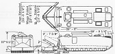
| Combat weight (land) | 97,500lbs 44,200kg |
Height | 128.5" 326.4cm |
| Length overall | 477.25" 1,212.2cm |
Gun overhang forward | 0" |
| Width with excavator wings extended | 225.25" 572.14cm |
Tread | 116.7" 296.4cm |
| Ground clearance, sides | 11.0625" 28.0988cm |
Ground pressure, 2" (5cm) penetration | 9.5psi .67kg/cm² |
| LVTE1: Armament | ||||
| Type | Mount | Ammunition | Traverse | Elevation |
| .30cal M1919A4 MG | Cupola mount G-1 | 2,000 rounds (250 ready) |
360° (manual) |
+60° to -15° (manual) |
| Aiming equipment | ||||
| Periscope M25C for gunner | ||||
| LVTE1: Armor | |||
| Assembly | |||
| Welding | |||
| Hull | |||
| Rolled homogeneous steel | |||
| Maximum | .625" 1.59cm |
Minimum | .25" .64cm |
| LVTE1: Automotive | |||||
| Engine | Continental LV-1790-1; 12 cylinder, 4 cycle, 90° vee gasoline | ||||
| Horsepower | Net: 704@2,800rpm Gross: 810@2,800rpm |
Torque | Net: 1,440 ft-lb@2,000rpm Gross: 1,610 ft-lb@2,200rpm |
Fuel capacity | 560gal 2,100L |
| Transmission | Allison CD-850-4A or -4B, 2 ranges forward, 1 reverse | ||||
| Steering | Mechanical, wobble stick | ||||
| Brakes | Multiple plate, oil cooled | ||||
| LVTE1: Suspension | ||
| Type | Road wheels | Track return rollers |
| Torsilastic | 9 pairs of dual/track | 5 dual/track |
| Drive sprockets | Idlers | Shock absorbers | 17-tooth rear drive | Dual compensating at front of track | None |
| LVTE1: Track | |||||||
| Center guide, single pin, steel with inverted grouser | |||||||
| Width | 20.75" 52.71cm |
Pitch | 5" 13cm |
Shoes/track | 134 | Ground contact length | 229.25" 582.30cm |
| LVTE1: Performance | |||
| Max level road speed | 24.9mph 40.1kph |
Max water speed | 6.2mph 10kph |
| Max trench | 120" 300cm |
Max grade | 60% |
| Max sideslope | 60% | Max vertical obstacle | 21" 53cm |
| Min turning diameter | Pivot | Max fording depth | Floats |
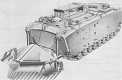
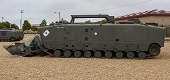
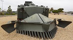
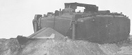
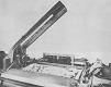
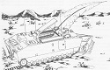
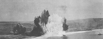
LVTE1 was the engineer version of the LVTP5. A large, toothed, V-shaped excavator blade was mounted on the front of the vehicle, and it could clear a path through a minefield that was 16" (41cm) deep and 12 feet (3.7m) wide. Plastic foam-filled buoyancy tanks were fitted to the rear of the blade to help the LVTE1 keep the right attitude while afloat, and explosive bolts could be issued during combat to jettison the blade should it become damaged or otherwise a hindrance. A rocket-propelled line charge was carried in either side of the cargo compartment, and these were elevated hydraulically. The used line charge pallet was discarded after firing. The familiar machine gun cupola was installed between the commander and driver.
Late-production LVTE1s were powered by the Continental AVI-1790-8 12-cylinder, fuel injected gasoline engine found on the 90mm gun tank M48A2. These vehicles did not feature recessed radiator compartments on the rear sides, and also lacked the armored covers for the engine air intake and exhaust on the rear deck.
