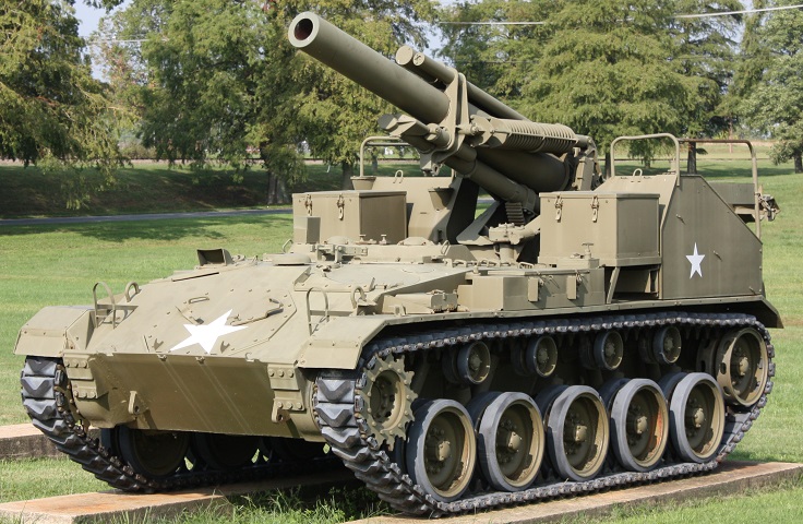
155mm Howitzer Motor Carriage M41 at the US Army Ordnance Museum.
The chassis of the M24 Chaffee light tank is still visible in its modified form as the 155mm HMC M41. The M41 has an extra track return roller to compensate for the increased length. This vehicle is wearing the T85E1 rubber chevron tracks. (Photo by Richard S. Eshleman.)
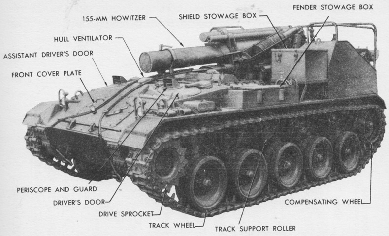
The drivers' periscopes are raised, the howitzer is protected by its canvas cover, and stowage boxes are mounted on the howitzer shield and fenders. (Picture from TM 9-744 155-mm Howitzer Motor Carriage M41.)
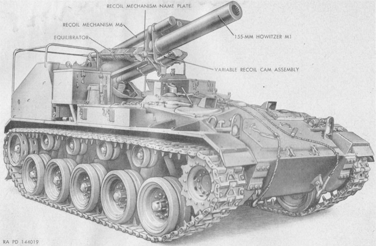
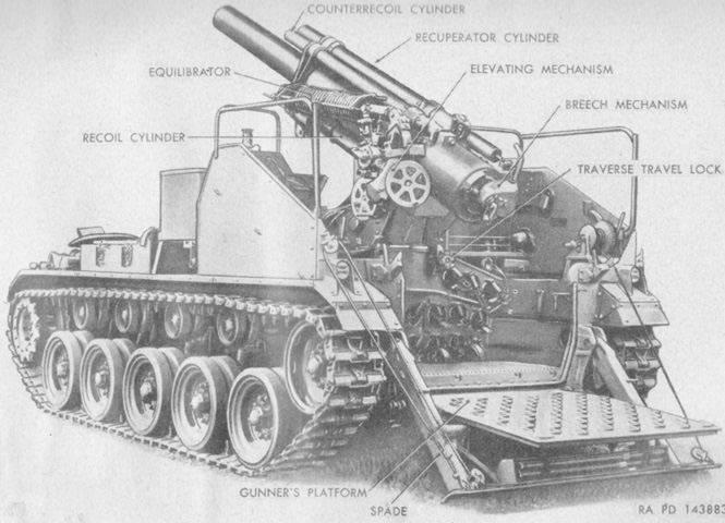
The vehicle is seen from the opposite side here, with parts of the recoil system labeled. (Picture from TM 9-331B 155-mm Howitzer M1 and Mount M14 (Mounted on 155-mm Howitzer Motor Carriage M41).)

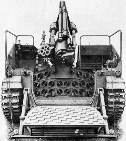
The rear of the carriage was dominated by the recoil spade and folded gunner's platform. (Picture from TM 9-744 155-mm Howitzer Motor Carriage M41.)
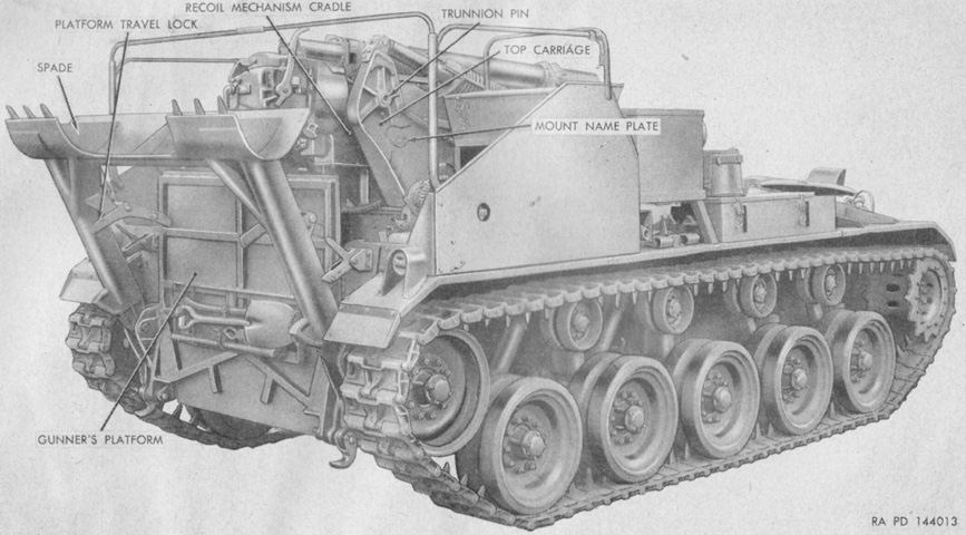
Further details from the rear are labeled here. (Picture from TM 9-331B 155-mm Howitzer M1 and Mount M14 (Mounted on 155-mm Howitzer Motor Carriage M41).)
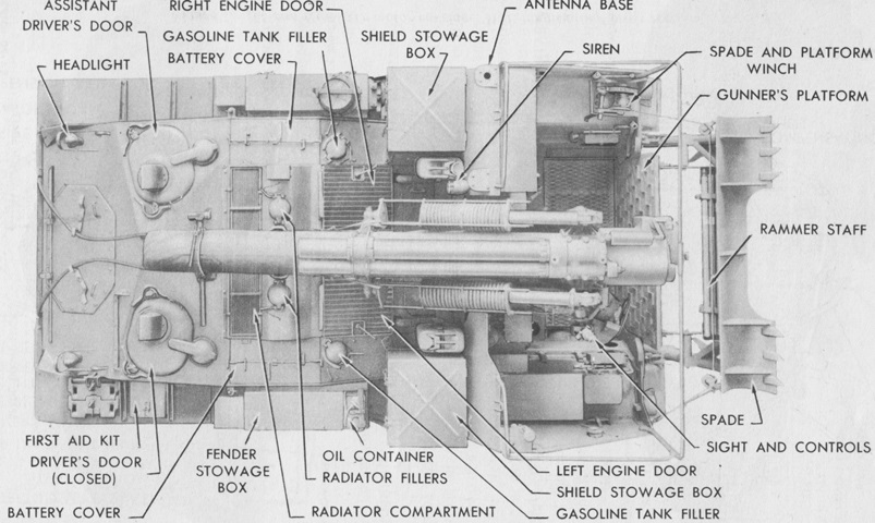
The similar layout to the twin 40mm gun motor carriage M19 can be seen from above. (Picture from TM 9-744 155-mm Howitzer Motor Carriage M41.)
In contrast to the M19, however, a shell ejection chute was not present in the hull floor. (Picture from TM 9-744 155-mm Howitzer Motor Carriage M41.)
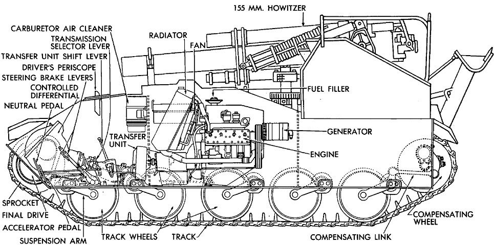
This cross-sectional sketch shows the internal changes made to the M24, including moving the engine and adding another road wheel. (Picture from TM 9-17-29C Ordnance Maintenance--Light Tank M24 and 155-mm Howitzer Motor Carriage M41 Tracks, Suspension, Hull and Turret.)

The revised engine deck is detailed in this image. (Picture from TM 9-744 155-mm Howitzer Motor Carriage M41.)
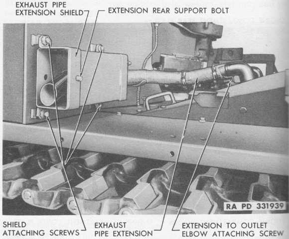
An exhaust pipe extension and shield are labeled here. (Picture from TM 9-744 155-mm Howitzer Motor Carriage M41.)

Two 12-volt, 6-cell batteries were connected in series to provide for a 24-volt system. One battery was housed on each side of the carriage above the front of each fuel tank. (Picture from TM 9-744 155-mm Howitzer Motor Carriage M41.)
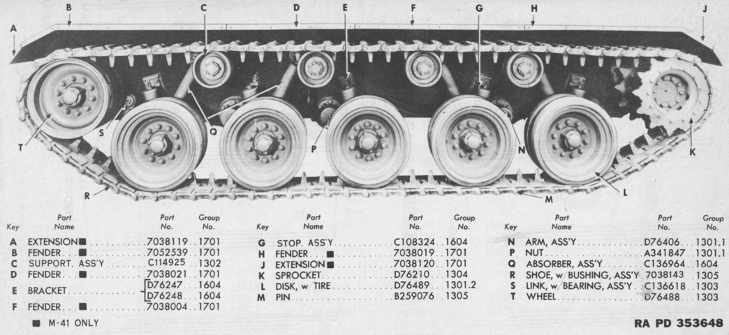
Details of the lengthened suspension can be gleaned from this picture. Note the fourth return roller and that the rear three road wheels are leading. (Picture from ORD 9 SNL G-236 (Includes SNL G-238).)
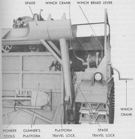
The rear spade and platform are shown here, and stowage of the pioneer tools can be seen. The hand-operated winch raised and lowered the platform and spade assembly. (Picture from TM 9-744 155-mm Howitzer Motor Carriage M41.)

The winch is seen from the front right and left rear, respectively. It was a Sasgen Derrick Co. R 100 single-speed, brake and pawl controlled, hand operated type with two crank handles so that it could be operated from inside the howitzer compartment or from outside the vehicle. (Picture from TM 9-744 155-mm Howitzer Motor Carriage M41.)
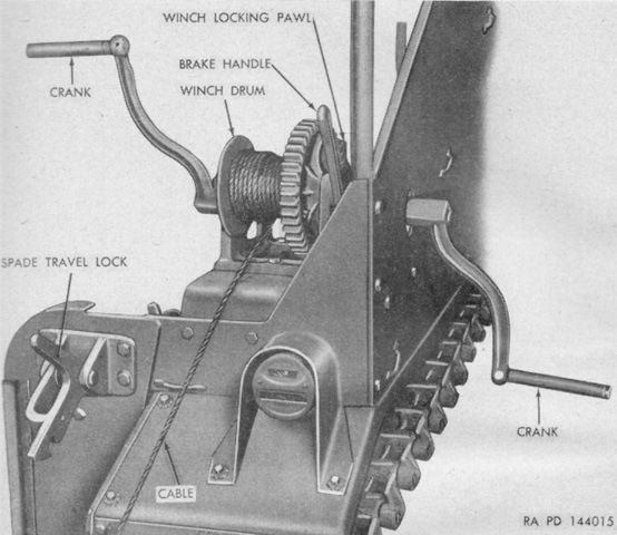
The winch cranks are attached here. Once the spade and platform locks were released, the brake was gradually released until the spade was completely lowered. Then the vehicle was reversed so that the spade buried itself well into the ground for stabilization. (Picture from TM 9-331B 155-mm Howitzer M1 and Mount M14 (Mounted on 155-mm Howitzer Motor Carriage M41).)
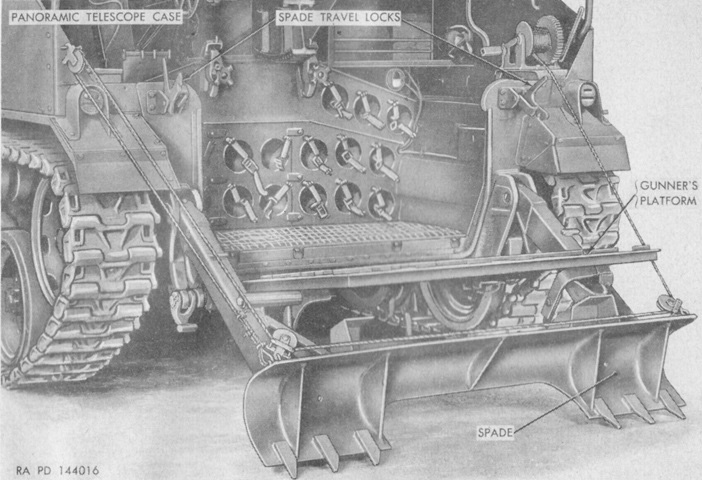
The spade had travel locks that attached it to the rear hull, while the platform's travel locks attached the platform to the spade. (Picture from TM 9-331B 155-mm Howitzer M1 and Mount M14 (Mounted on 155-mm Howitzer Motor Carriage M41).)
The rear spade and platform are lowered in this image, showing the howitzer mount and ammunition stowage below it. (Picture from ORD 9 SNL G-236 (Includes SNL G-238).)
The lowered gunner's platform is shown from another angle here. (Picture from TM 9-331B 155-mm Howitzer M1 and Mount M14 (Mounted on 155-mm Howitzer Motor Carriage M41).)

In addition to the travel lock on the front hull, two traversing lock clamps were installed on the rear of the howitzer mount. In order to loosen the traversing lock clamp nut, a utility bar was to be inserted into the holes in the clamp nut to rotate it. (Picture from TM 9-744 155-mm Howitzer Motor Carriage M41.)
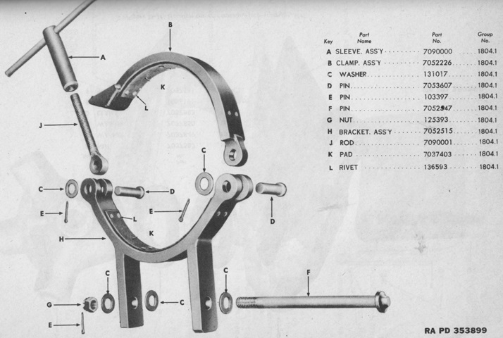
The construction of the howitzer travel lock is revealed in this diagram. (Picture from ORD 9 SNL G-236 (Includes SNL G-238).)
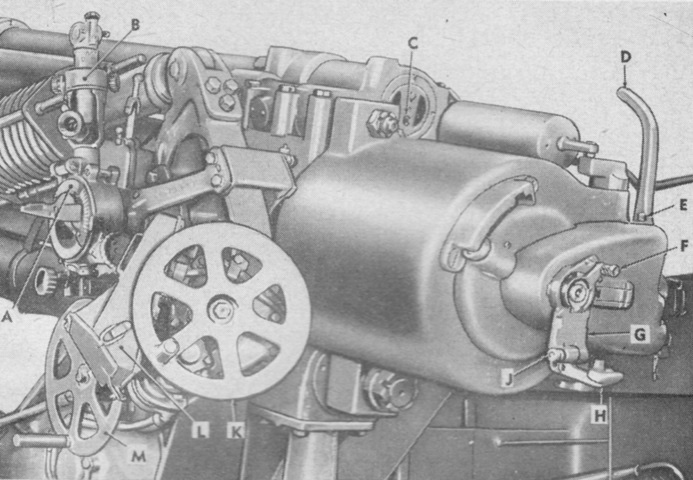
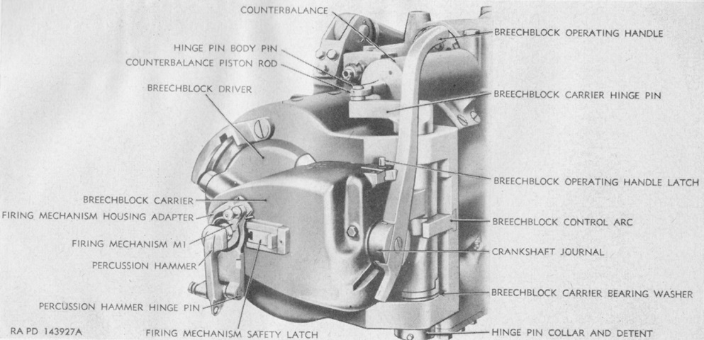
The operating controls for the gun mount are labeled here. The howitzer mount M14 weighed 6,292lb (2,854kg) complete with the howitzer, recoil mechanism, top carriage, and equilibrators, but without the howitzer cover and accessories. The electric elevation system handle was found in the electric elevating mechanism control box. One complete turn of the elevation handwheel produced 14.8 mils of elevation or depression. A. Telescope mount. B. Panoramic telescope. C. Recuperator cylinder oil index. D. Breechblock operating handle. E. Breechblock operating handle latch. F. Firing mechanism locking plunger handle. G. Firing mechanism housing adapter. H. Percussion hammer. J. Percussion hammer locking pin knob. K. Electric elevating mechanism handwheel. L. Electric elevating mechanism control box. M. Traversing handwheel. (Picture from TM 9-331B 155-mm Howitzer M1 and Mount M14 (Mounted on 155-mm Howitzer Motor Carriage M41).)
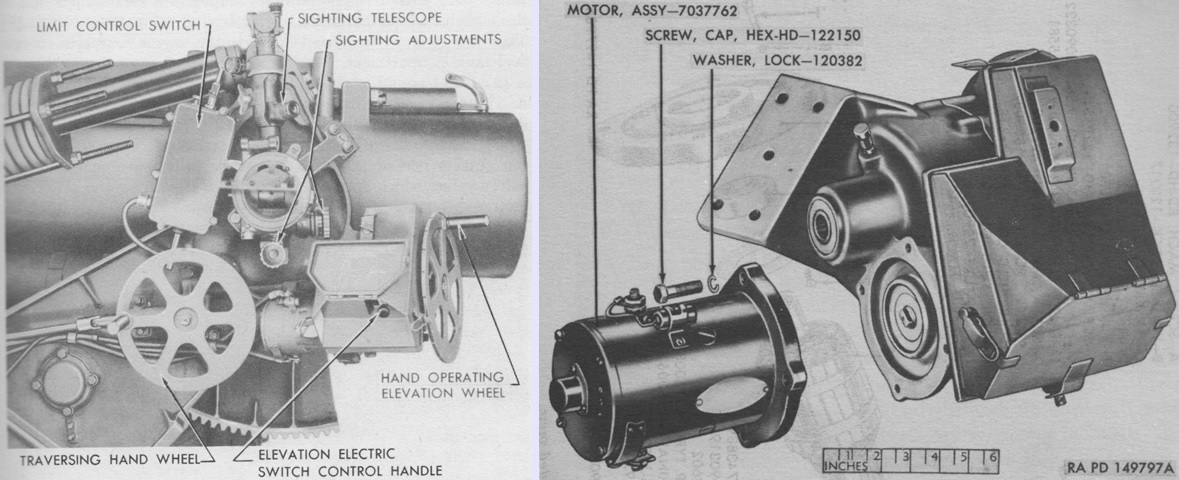
The electric elevation control lever is seen on the left. To use the electric elevation mechanism, the lever was moved to the left from the MANUAL position to either the UP or DOWN positions. A partially exploded view of the electric elevating mechanism is on the right. (Picture from TM 9-744 155-mm Howitzer Motor Carriage M41 and TM 9-3043 Ordnance Maintenance: 155-mm Howitzer M1; Recoil Mechanisms M6, M6A1, M6A2, M6B1, and M6B2; 155-mm Howitzer Carriages M1A1 and M1A2; and 155-mm Howitzer Mount M14.)
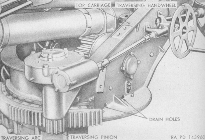
The traversing mechanism was manual only, and used the traversing pinion to mesh with the stationary traversing arc. Each turn of the handwheel produced 10.3 mils of traverse. (Picture from TM 9-331B 155-mm Howitzer M1 and Mount M14 (Mounted on 155-mm Howitzer Motor Carriage M41).)
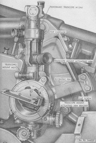
The azimuth-compensating type telescope mount M25 is holding the panoramic telescope M12A6. The mount had an elevating scale and longitudinal leveling micrometer to lay the howitzer in elevation. When its bubble was centered, the mount's leveling vial placed the telescope's azimuth scale in a true horizontal plane.
The telescope M12A6 was a 4x instrument with a 10° field of view, and its eyepiece was offset 45° to allow the user to stand clear of the howitzer. It was used to lay the howitzer in azimuth during indirect fire, and during direct fire it was used to lat the howitzer in both azimuth and elevation. (Picture from TM 9-331B 155-mm Howitzer M1 and Mount M14 (Mounted on 155-mm Howitzer Motor Carriage M41).)
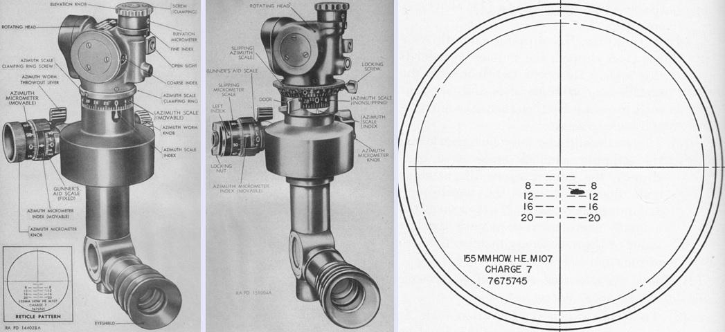
The panoramic telescope M12A6 is shown on the left, and the M12A7G in the center. The M12A7G improved upon the M12A6 by adding a slipping azimuth scale with a locking screw; a nonslipping azimuth scale that turned with the rotating head, and a door for this scale that allowed reading of the nonslipping azimuth scale when opened or provided an index for the slipping azimuth scale when closed; a slipping azimuth micrometer scale with a locking nut; and a nonslipping left index that moved by turning the azimuth micrometer knob. The reticle pattern is detailed on the right. The cross lines were used for indirect fire, and the range graduations for direct fire. The direct fire range lines were numbered in hundreds of yards, and each horizontal line and space represented a 5-mil deflection. In the sketch, the gunner is firing on a tank at 1,000 yards (910m) range with a 10-mil lead. In early vehicles, the panoramic telescope M12 was used, and the telescope M69D for direct fire. The M69D was deleted with the introduction of the panoramic telescope M12A6. (Picture from TM 9-331B 155-mm Howitzer M1 and Mount M14 (Mounted on 155-mm Howitzer Motor Carriage M41) and FM 6-82 155-mm Howitzer M1, on Motor Carriage M41.)
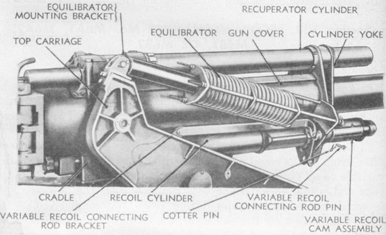
The recoil system is labeled in this picture. One of five recoil mechanisms were used: the recoil mechanism M6 7141823 was only designed to be used in temperatures down to approximately -20°F (-30°C); M6A1 7148146 was an M6 modified with a spacer in the floating piston, automotive and artillery grease inserted in the floating piston, and low-temperature type packing fillers and petroleum base hydraulic oil for recoil fluid, allowing it to be used to -65°F (-54°C); M6A2 7148074 was a new-manufacture M6-type mechanism with a one-piece floating piston, low-temperature packing fillers, automotive and artillery grease in the floating piston, and petroleum base oil as recoil fluid; M6B1 7141824 was an alternate to and had similar performance as the M6; and M6B2 7148147 was an M6B1 modified with the same improvements as the M6A1. The variable recoil cam assembly reduced the length of the recoil as elevation was increased. (Picture from TM 9-331B 155-mm Howitzer M1 and Mount M14 (Mounted on 155-mm Howitzer Motor Carriage M41).)
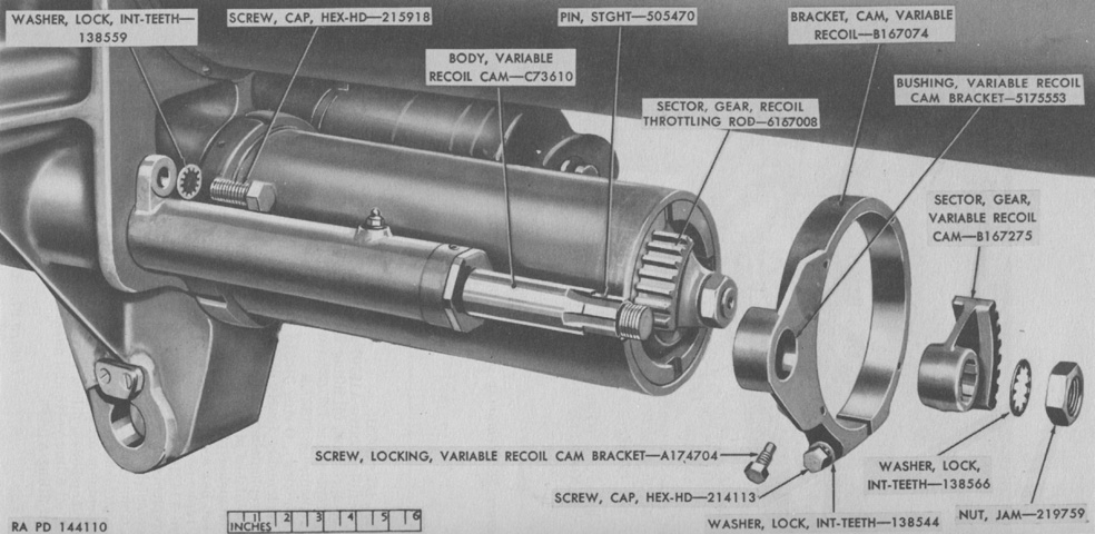
The variable recoil mechanism cam bracket and gear sector have been exploded in this image. (Picture from TM 9-3043 Ordnance Maintenance: 155-mm Howitzer M1; Recoil Mechanisms M6, M6A1, M6A2, M6B1, and M6B2; 155-mm Howitzer Carriages M1A1 and M1A2; and 155-mm Howitzer Mount M14.)
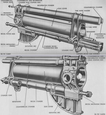
The recoil mechanism has been isolated and is seen from the right front at the top and from the left rear at the bottom. Both the M6 and M6B1 contained a two-piece type floating piston; the M6B1 differed by utilizing monel in its construction. The M6A2 used unified standard threads as opposed to the metric threads found in the M6, M6A1, M6B1, and M6B2. The recoil mechanism weighed 1,582lb (717.6kg) and used 4gal (15L) of oil in the recoil cylinder, 2gal (7.6L) in the counterrecoil and recuperator cylinder, and 1 pint (473mL) as reserve. Its initial nitrogen pressure was 1,500psi (105kg/cm²), and maximum nitrogen pressure was 2,250psi (158kg/cm²). Resistance to recoil at 0° elevation was 39,400lb (17,900kg), and maximum piston rod pull at maximum elevation was 61,320lb (27,810kg). (Picture from TM 9-3043 Ordnance Maintenance: 155-mm Howitzer M1; Recoil Mechanisms M6, M6A1, M6A2, M6B1, and M6B2; 155-mm Howitzer Carriages M1A1 and M1A2; and 155-mm Howitzer Mount M14.)
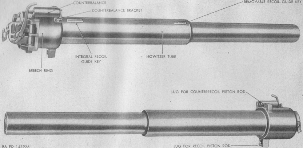
The tube of the 155mm howitzer M1 was machined to form a bearing surface which slid in the recoil mechanism cradle and cylinder yoke during recoil and counterrecoil. The howitzer had a muzzle velocity of 1,850 feet per second (564m/s) using a 94.80lb (43.00kg) projectile and a 13.91lb (6.310kg) powder charge. Maximum range was 16,355 yards (14,955m), and estimated life accuracy was 15,000 rounds. Firing rate was rapid bursts of 3 rounds per minute or sustained firing of 1 round per minute. Its length of bore was 23.0 calibers, and it weighed 3,825lb (1,735kg). (Picture from TM 9-331B 155-mm Howitzer M1 and Mount M14 (Mounted on 155-mm Howitzer Motor Carriage M41).)
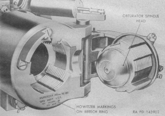
The howitzer tube screwed into the front of the breech ring and was secured with a locking screw. (Picture from TM 9-331B 155-mm Howitzer M1 and Mount M14 (Mounted on 155-mm Howitzer Motor Carriage M41).)
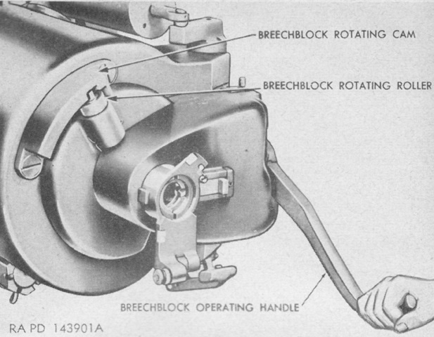
To open the breech, the breechblock operating handle latch was moved to the left, then the handle was swung backwards and down as far as it would go. (Picture from TM 9-331B 155-mm Howitzer M1 and Mount M14 (Mounted on 155-mm Howitzer Motor Carriage M41).)
The breech was a stepped-thread, interrupted-screw type. (Picture from TM 9-331B 155-mm Howitzer M1 and Mount M14 (Mounted on 155-mm Howitzer Motor Carriage M41).)
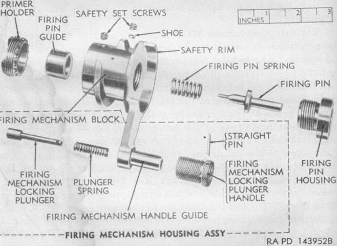
The firing mechanism M1 contained the firing pin which, when struck by the percussion hammer after it was actuated by a lanyard pull, impacted and detonated the primer which ignited the propellant charge. (Picture from TM 9-331B 155-mm Howitzer M1 and Mount M14 (Mounted on 155-mm Howitzer Motor Carriage M41).)
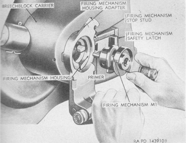
The firing mechanism was removed from the breech and a new primer inserted before each round was fired. (Picture from TM 9-331B 155-mm Howitzer M1 and Mount M14 (Mounted on 155-mm Howitzer Motor Carriage M41).)
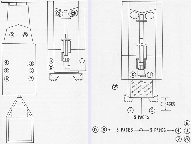
The gun section is shown on the left in its mounted positions. The howitzer motor carriage was accompanied by a utility vehicle towing a trailer M10. The entirety of the gun section personnel was comprised of the chief of section (CS), gunner (G), two drivers (D), the ammunition corporal (AC) in charge of the utility vehicle, and eight cannoneers (1-8). Cannoneer number 1 was also the assistant gunner.
The posts of the section prepared for action are illustrated on the right. After the ammunition was unloaded, the driver of the utility vehicle was to take it to the truck park or some other point indicated by the ammunition corporal.(Picture from FM 6-82 155-mm Howitzer M1, on Motor Carriage M41.)
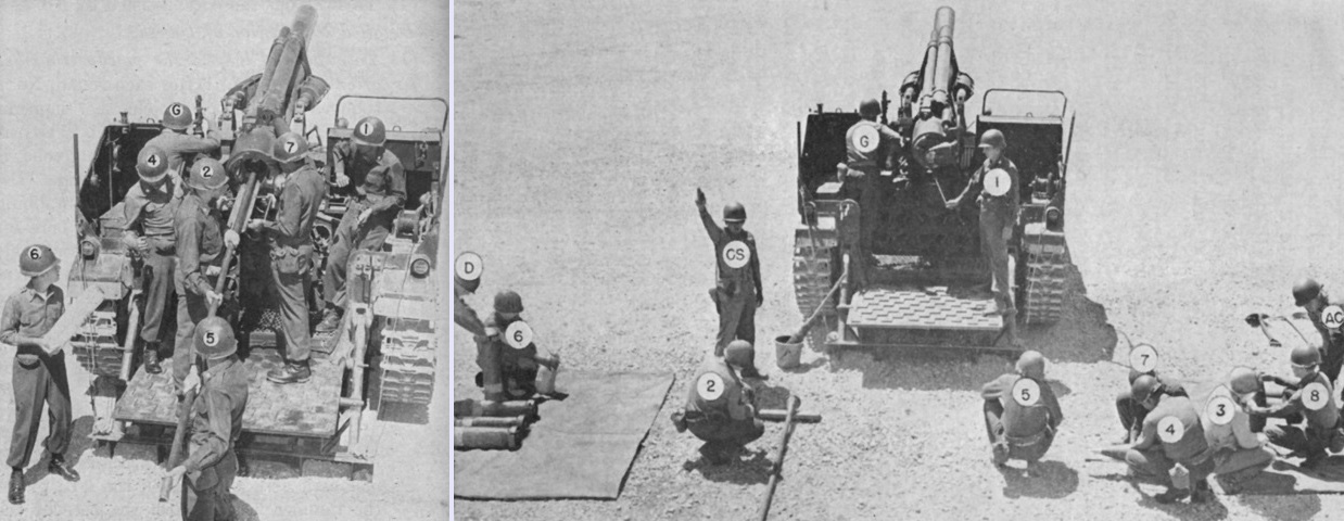
On the left, the section is depicted placing a projectile into the chamber. The assistant gunner was responsible for opening and closing the breech.
The howitzer is loaded and ready to fire in the right-hand image, with the section at their posts. The visual signal for firing was the chief of section sharply dropping his right arm to his side, at which point the assistant gunner would pull the lanyard to fire the ordnance. If the arm signal could not be seen, oral fire commands were used. (Picture from FM 6-82 155-mm Howitzer M1, on Motor Carriage M41.)
