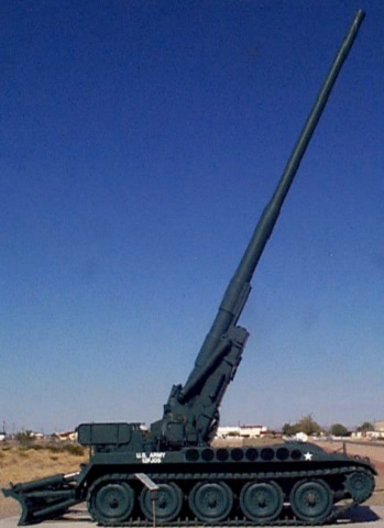
175mm Self-propelled Gun M107 at the Marine Corps Air Ground Combat Center..
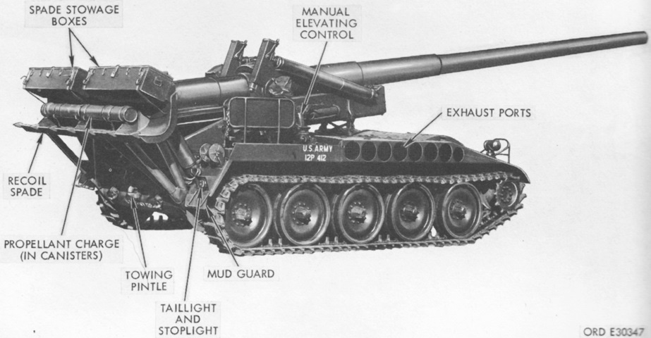
The M107 and 8" SPH M110 shared a common chassis mounting different weapons. The very large (60 caliber) 175mm gun dominates this view, and it becomes obvious why it was stowed in a retracted position for travel. The exhaust ports are visible on the right side of the vehicle near the front-mounted engine, and the rear stabilizing spade is lowered. Note that there is a distinct constriction of the gun tube about halfway along its length. The 175mm gun M113 weighed ~13,800lb (~6,260kg) complete, with the breech mechanism and barrel assemblies weighing ~405lb (~184kg) and ~12,050 (~5466kg), respectively. (Picture courtesy Mark Holloway.)
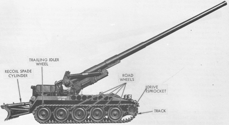
The ordnance is stowed in its recoil position, and the cradle travel lock is engaged. A seat for the crew is visible at the right rear corner of the hull. (Picture from TM 9-2300-216-10.)
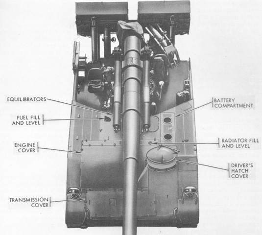
The driver sat to the left of the powerplant, which was located under the humped cover at the right front corner of the hull. The hull was 58.13" (147.7cm) tall. (Picture from TM 9-2300-216-10.)
The even with the gun in travel position, the front overhang was substantial. (Picture from TM 9-2300-216-10.)
When not stabilizing the vehicle, the recoil spade was used to augment the sparse stowage area available. (Picture from TM 9-2300-216-10.)
The recoil spade is shown here in the lowered position. It was actuated hydraulically via a control lever that was rotated in the desired direction after being pulled out towards the user. (Picture from TM 9-2300-216-10.)
The overall layout of the vehicle is visible from above. The crew seat at the hull's right rear corner is folded, and the shell loader and rammer can be seen on the opposite side of the gun. (Picture from TM 9-2300-216-10.)
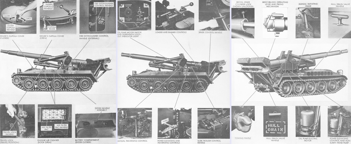
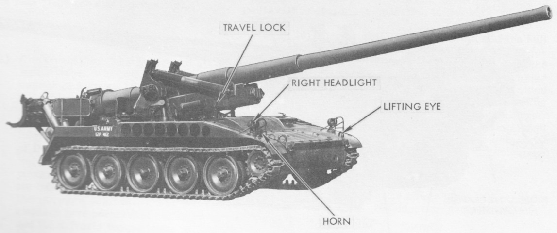
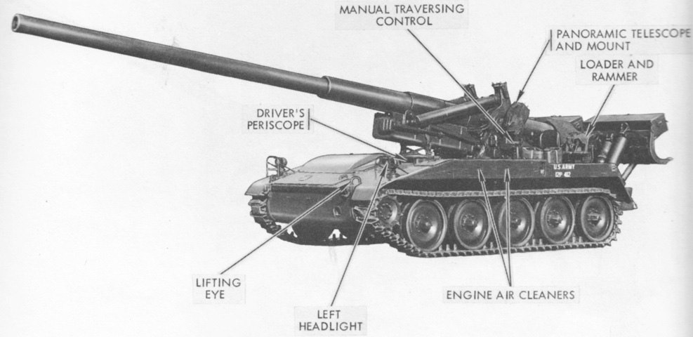
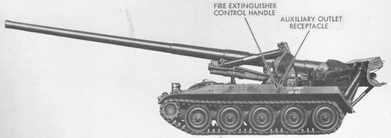
Various external controls are illustrated in these three images. (Picture from TM 9-2300-216-10.)
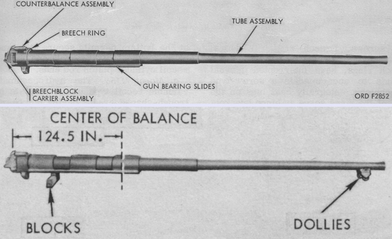
The 175mm gun cannon M113 is detailed at the top, and its center of balance is noted at the bottom. The cannon consisted of a built-up or laminated tube with a chrome-plated chamber and bore. It was aligned in its mount by longitudinal rails secured to three hoops shrunk onto the jacket. It was 428" (1,090cm) long, with 349.16" (886.87cm) of rifling. The M113's tube had an EFC life of 400 rounds, while the M113A1's autofrettaged tube extended this to 1,200 rounds. M113s with serial numbers 1 through 337 were not to be retubed with M113A1 gun tubes. (Picture from TM 9-1000-218-35.)
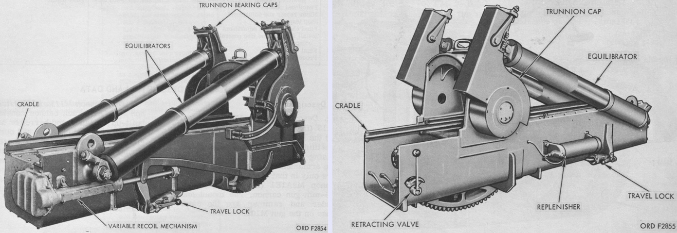
The M158 was an hydropneumatic, variable recoil type mount consisting of a trough-shaped cradle with gun bearing slides that supported and maintained the gun's precise alignment during recoil and counterrecoil. The cradle also enclosed the recoil, counterrecoil, and recuperator cylinders and supported the replenisher and variable recoil mechanism. (Picture from TM 9-1000-218-35.)
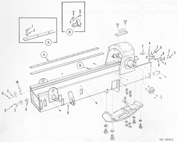
An exploded view of the mount cradle and its related parts is drawn here. (Picture from TM 9-2300-216-20P C2.)
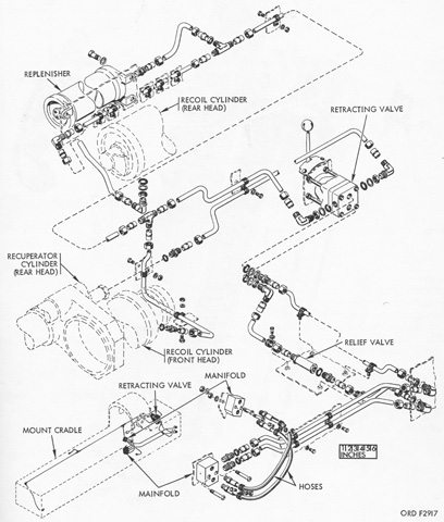
The hydraulic lines for the mount M158 are diagrammed. (Picture from TM 9-1000-218-35.)
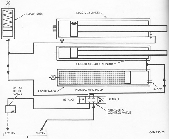
A schematic of the hydropneumatic variable recoil system is sketched here. Note the retracting control valve, which allowed the cannon to be withdrawn into the travel position or moved forward into the firing position. The recoil system used 15gal (57L) of 9150-255-4443 oil and weighed 3,925lb (1,780kg). (Picture from TM 9-2300-216-10.)
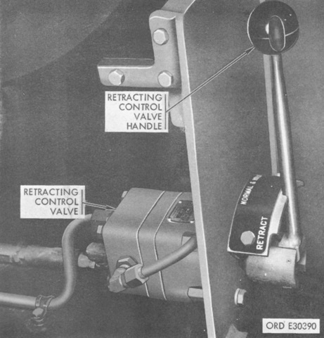
The retracting control valve was a detent valve that actuated the recoil cylinder to retract the gun to the travel position or to connect the replenisher cylinder to the recoil cylinder during firing. The RETRACT position withdrew the ordnance to the travel position; the RETURN position returned the gun to battery and charged the recuperator cylinder; and the NORMAL AND HOLD position held the cannon in the traveling or firing positions. (Picture from TM 9-2300-216-10.)
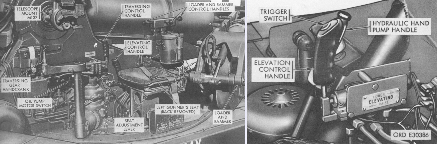
The controls on the left and right sides of the turret are shown in the left and right images, respectively. (Picture from TM 9-2300-216-10.)
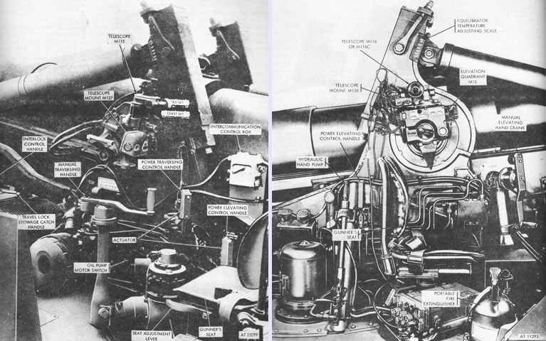
The left and right sides of the turret are again seen on the left and right, respectively. (Picture from TM 9-2300-216-10 C6.)
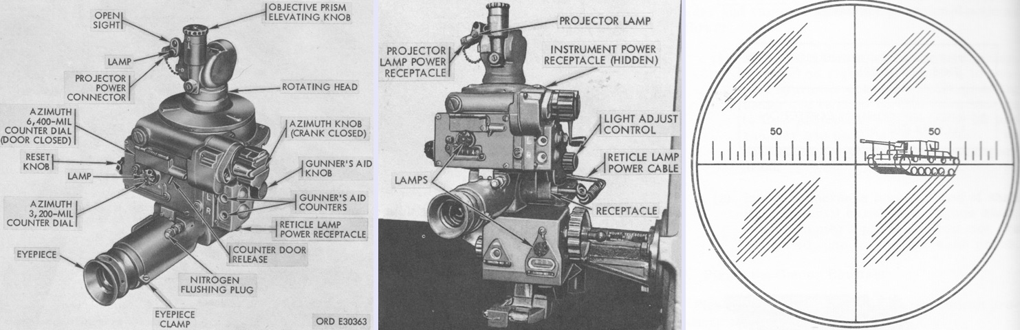
The panoramic telescope M115 is shown isolated on the left and installed in the telescope mount M137 in the center. The M115 was 4x fixed telescope with a 10° field of view that was used by the left gunner in laying the gun in azimuth for indirect fire, or in direct fire against stationary or moving targets in combination with the right gunner using the elbow telescope M116C. The M115 could be used in direct fire alone in an emergency, but was restricted to engaging stationary targets only. The head could rotate through 6,400 mils of azimuth and elevate ±300 mils from the horizontal setting. The reticle pattern is sketched on the right, with the gunner engaging a tank. The horizontal line was graduated into 5-mil increments, with the 50 mil line on each side of the center vertical line being marked. (Picture from TM 9-2300-216-10.)
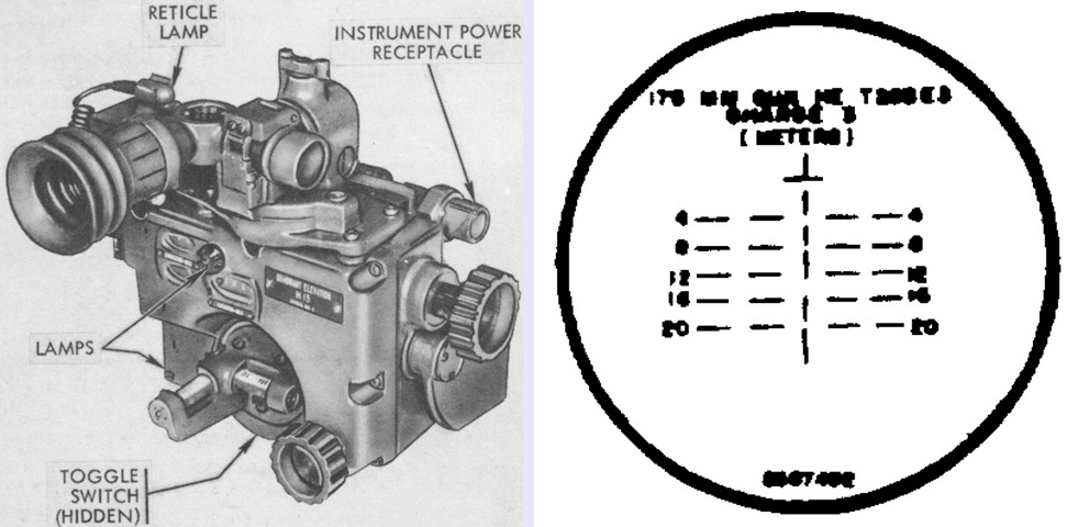
The elbow telescope M116C was a simple, fixed-focus 3x device that is shown on the left installed in the telescope mount M138 atop the elevation quadrant M15. It was used by the right gunner to lay the gun in elevation for direct fire. Its reticle pattern is fuzzily sketched on the right, with the horizontal lines being marked in hundreds of meters. (Picture from TM 9-2300-216-10 and TM 9-1240-288-35P.)
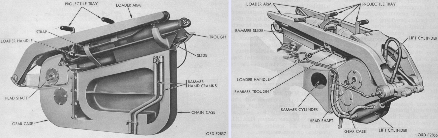
A Pacific Car and Foundry Company hydraulically-powered loader and rammer was mounted and pivoted on the trunnion to the side of the breech. It lifted and loaded shells into the breech, with ramming accomplished by a sprocket-driven rammer chain with a rubber-padded and wheeled head. The unit was hydraulically traversed into or out of position, and interlock switches disabled the elevating and ramming circuits to prevent premature energizing of the shell lifting or ramming systems. The loader and rammer were also equipped with hand controls for emergency use. The hand cranks were inserted into the ends of the rammer head shaft. (Picture from TM 9-1000-218-35.)
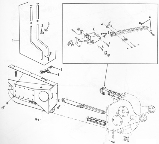
The makeup of the rammer chain can be gleaned from this exploded view of the chain, cylinder, and case group. (Picture from TM 9-2300-216-20P C2.)
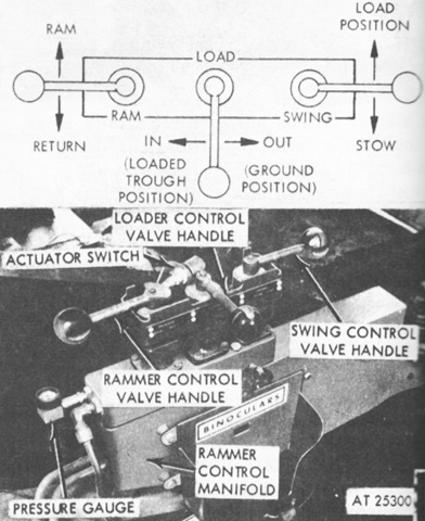
The controls for the loader and rammer are highlighted here. The swing control valve moved the rammer between the stowed position beside the left-side gunner's seat and the load position behind the ordnance. The loader control valve operated the loader arm to lower the arm to the ground and to raise a projectile from the ground to the rammer trough. The rammer control valve operated the ramming chain to ram a projectile into the breech. Proper ramming hydraulic pressure was 1,600-2,400psi (110-170kg/cm²). (Picture from TM 9-2300-216-10 C6.)
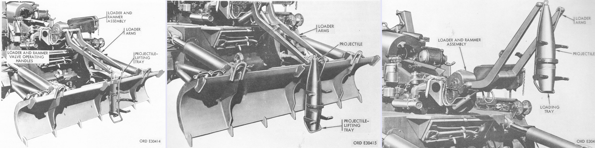
Operation of the projectile-lifting tray is illustrated in these three images. The assistance in the loading process was surely welcomed: the 175mm high-explosive projectiles M437A1 and M437A2 weighed 147.3lb (66.82kg), while the 8" high-explosive projectile M106 used in the M110 weighed 200.89lb (91.124kg). Though the loader and rammer were normally operated hydraulically, they could also be utilized via handcranks in the event of an hydraulic failure. (Picture from TM 9-2300-216-10.)
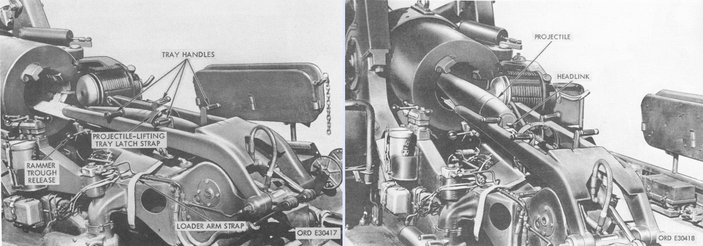
The projectile rammer trough is in the ram position on the left, and the projectile is being rammed into the breech by the rammer's chain in the right image. The headlink featured a pad that pushed on the base of the projectile. (Picture from TM 9-2300-216-10.)
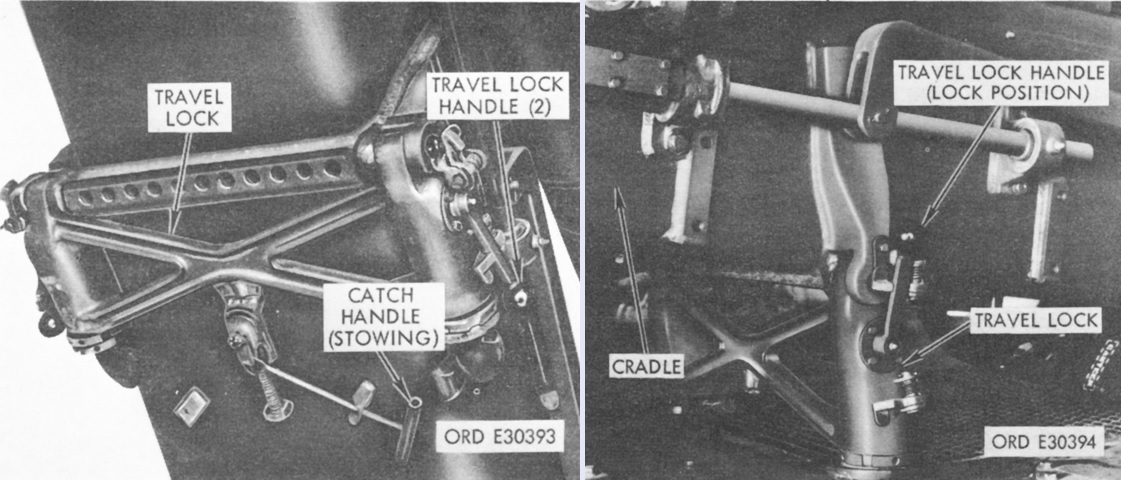
The cannon mount travel lock was found on the bottom of the ordnance cradle. The travel lock support was hinged so that it could be stowed when firing or engaged during travel. When in use, two latches engaged with recesses in the top of the hull. It is shown on the left stowed for firing, and on the right it is deployed in the travel position. (Picture from TM 9-2300-216-10.)
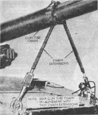
In addition to the cannon mount travel lock, the M107 was also equipped with a chain-type gun barrel travel lock that provided additional stabilization for the gun tube, especially when traversing rough terrain. (Picture from TM 9-2300-216-10 C6.)
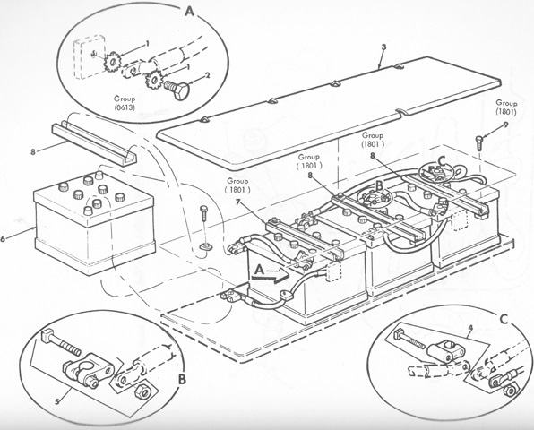
Four 12-volt type 6TN batteries were housed behind the driver for the vehicle's 24-volt electrical system. (Picture from TM 9-2300-216-20P C2.)
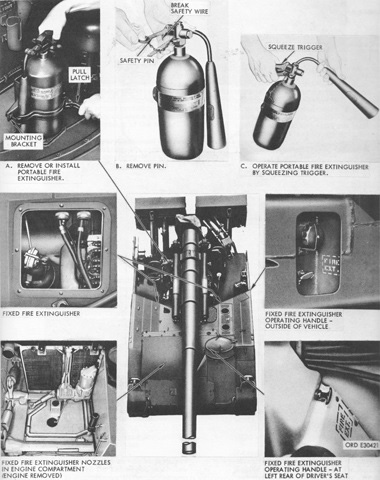
The fixed fire extinguisher system was composed of two 10lb (4.5kg) CO2 cylinders routed to the engine compartment. Remote control handles in the driver's compartment and on the hull left rear actuated the cylinders. In addition, a 5lb (2.3kg) portable CO2 extinguisher was stowed on the right side of the turret deck near the gun mount. (Picture from TM 9-2300-216-10.)
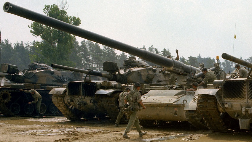
Though these M60A1 tanks belonging to A Company, 4th Battalion, 73d Armor would often be the big guns in a given situation, the 175mm gun on this British M107 almost comically dwarfs their 105mm M68s. The vehicles and men are taking part in a REFORGER exercise. (Picture taken 8 Jul 1978 by SPC5 Danny P. Finlay; available from the National Archives.)
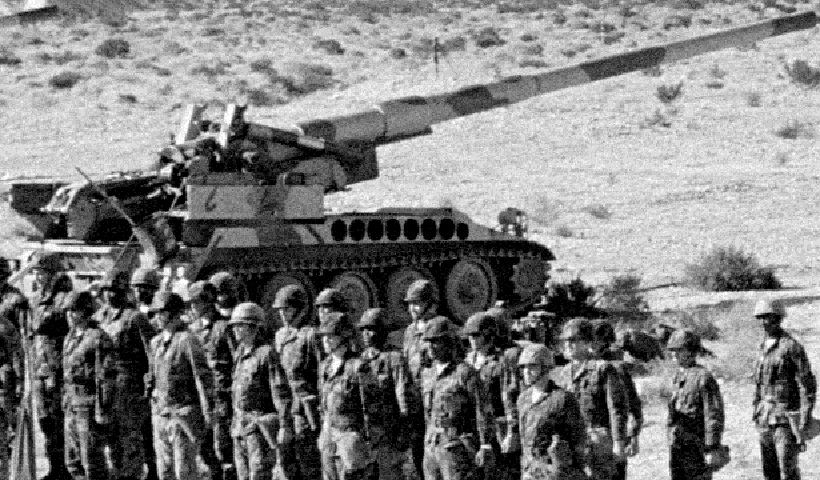
These Marines were part of 3rd Battery, 4th Battalion, 11th Marines, 1st Marine Division, and were at the last formation with their guns before they converted to 8" howitzers. (Picture taken by SGT C. A. Luedke; available from the National Archives.)
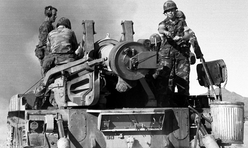
In this image, Gen William R. Etnyre of the 7th Marine Amphibious Brigade fires the last round from this gun before the Marines are converted to 8" howitzers. Details of the hydraulic recoil spade can be seen, and the bench seat for the loaders on the right is folded up out of the way. A toolkit bracket is on the rear of the hull, but the tools themselves are not carried. As shown here, the gun crew was offered protection from neither the elements nor the enemy. (Picture taken by SGT C. A. Luedke; available from the National Archives.)
