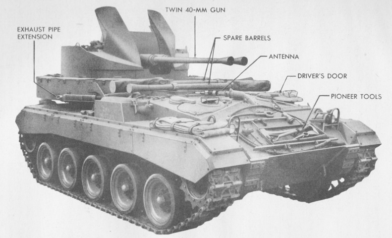
Twin 40mm Gun Motor Carriage M19.
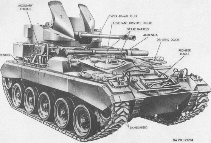
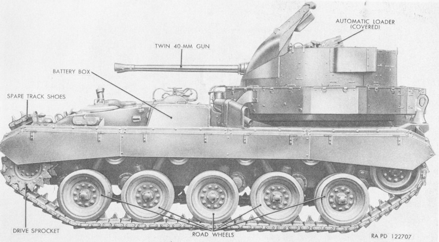
The lengthened chassis of the M19 necessitated an additional return roller compared to the M24 Chaffee on which it was based, although the return rollers in this image are hidden by the sand shields. The large 40mm gun turret occupied the rear of the hull, and the engine was moved to between the turret and the drivers' compartment. Pioneer tools are stowed on the hull front, and spare 40mm barrels are kept on the hull in front of the turret. A flexible antenna mount is visible on the front hull plate between the drivers; via a crank in the drivers' compartment, the antenna could be laid almost horizontally towards the vehicle's rear in order to avoid fouling on the 40mm guns. Ammunition bins were installed on the hull around the turret, and a battery box occupied the central position on each fender. (Picture from TM 9-757 Twin 40-mm Gun Motor Carriage M19.)
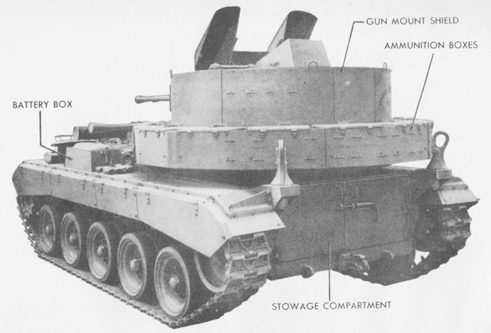
The rear of the vehicle is shown here. Large lifting eyes are present above the rear fenders. (Picture from TM 9-757 Twin 40-mm Gun Motor Carriage M19.)
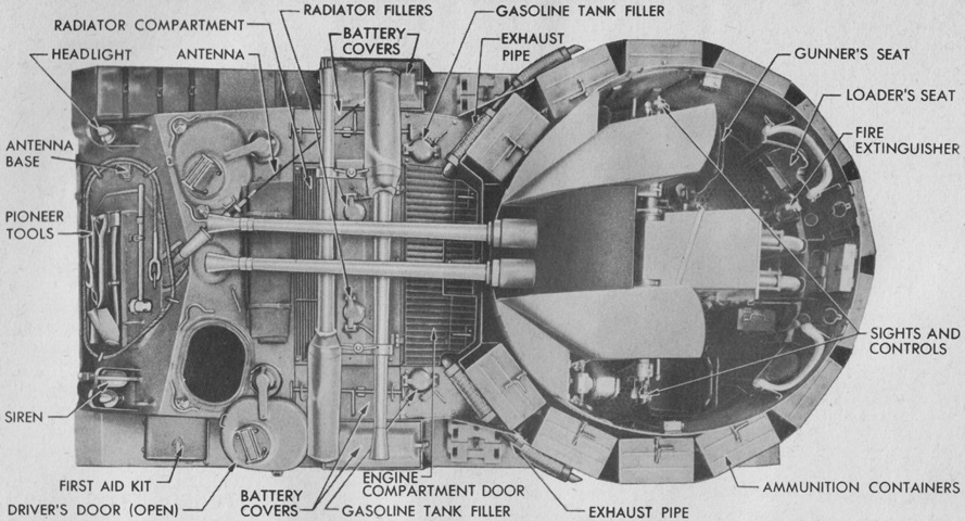
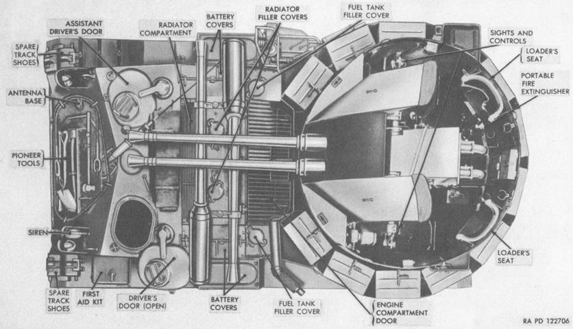
The relocated engine compartment and open-topped nature of the turret can easily be seen from above. (Picture from TM 9-757 Twin 40-mm Gun Motor Carriage M19.)
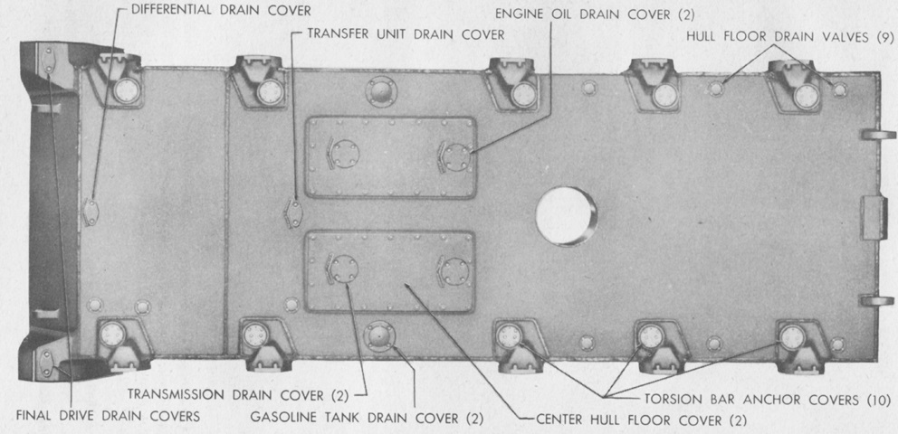
The various hull floor drain plugs and covers are labeled in this picture. The front of the vehicle is to the left; note the large shell ejection chute behind the center hull floor covers. There was also no escape hatch in the floor, in contrast to the light tank. (Picture from TM 9-757 Twin 40-mm Gun Motor Carriage M19.)
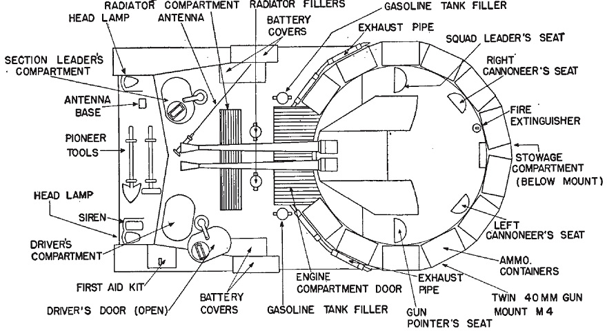
The stowage and crew positions are diagrammed in this image. (Picture from FM 44-62 Service of the Piece, Twin 40-mm Gun Motor Carriage M19.)
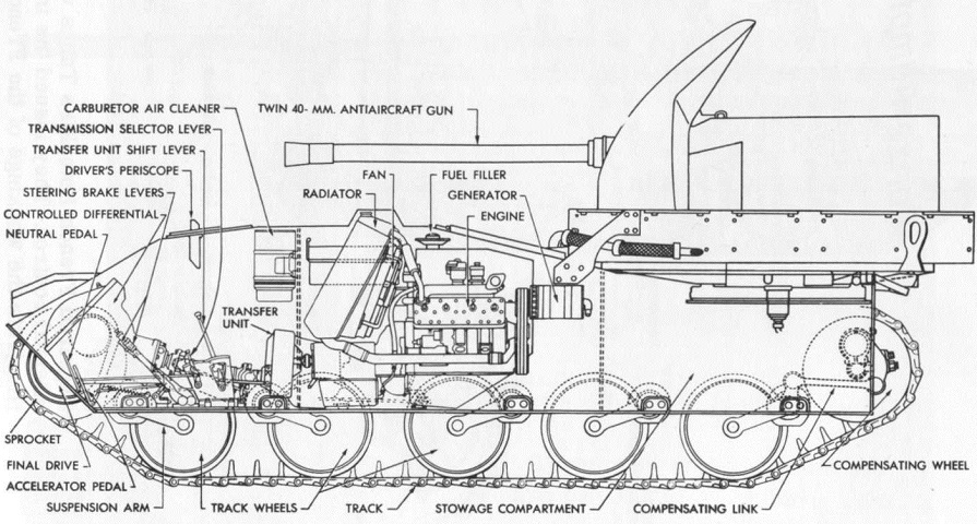
A cross-section of the vehicle is sketched here. (Picture from Tank Data, vol. 3.)
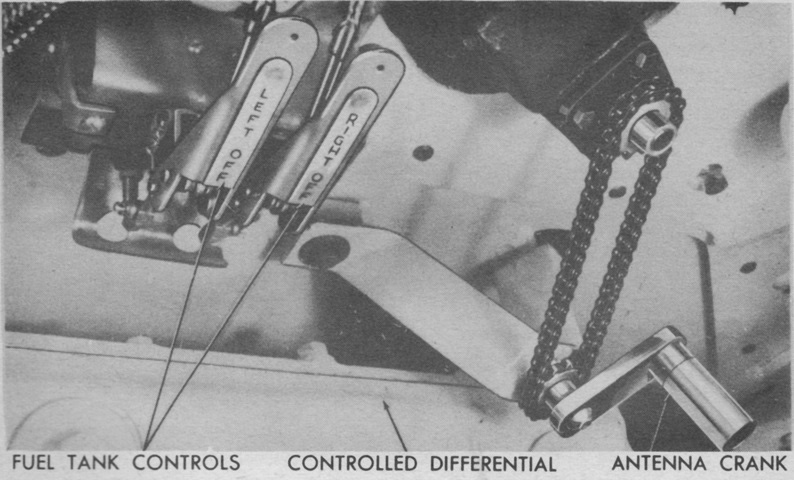
The hand crank for extending or lowering the radio antenna was in the front center of the driver's compartment next to the fuel tank controls. The best reception was achieved with the antenna upright, but when firing the guns or driving through brush it could be lowered to protect it from damage. (Picture from TM 9-757 Twin 40-mm Gun Motor Carriage M19.)
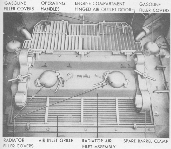
The features of the engine decking between the drivers and the 40mm gun mount are shown here. The spare barrels are absent, but their clamps are still present. (Picture from TM 9-757 Twin 40-mm Gun Motor Carriage M19.)
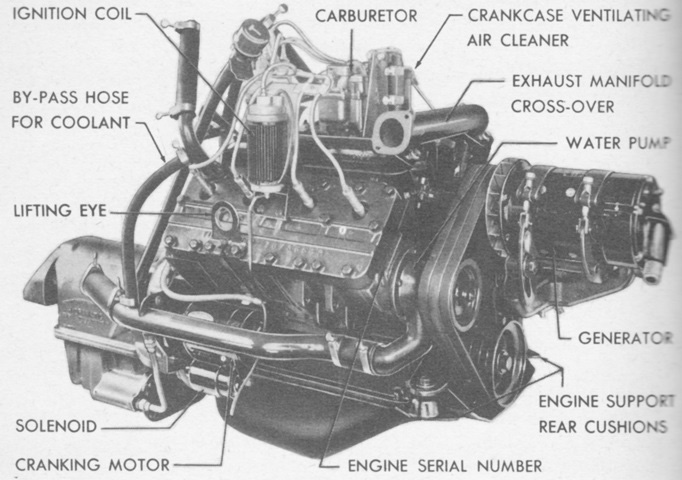
One of the Cadillac engines is shown here from the "front." Even though the generator end of the engines faced the rear of the vehicle, this side of the engine was considered the front, with the flywheel end considered the rear. The right and left engines were designated as if one was sitting in the driver's seat (i.e., the engine on the right side of the hull was the right-hand engine), however the right and left sides of each individual engine and transmission were determined as if one was standing at the transmission and facing the generator end of the engine. Each engine had a bore and stroke of 3.5" (8.9cm) and 4.5" (11cm), respectively, for a displacement of 346in³ (5,670cm³). The compression ratio was 7.06:1, and each engine and transmission assembly weighed 1,166lb (528.9kg). (Picture from TM 9-757 Twin 40-mm Gun Motor Carriage M19.)
The Hydramatic transmission was comprised of a fluid coupling and an automatic hydraulically-operated transmission with four forward speeds. The transfer unit provided high and low forward ranges, doubling the available forward gears, and also provided reverse. The fluid coupling end was considered the front, and the output shaft end was considered the rear. (Picture from TM 9-757 Twin 40-mm Gun Motor Carriage M19.)
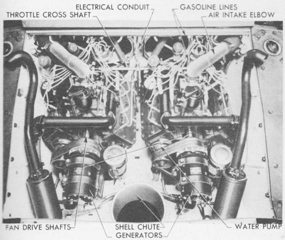
The engines are shown installed with the turret and engine decking removed. The fuel tanks are visible on the outside of the image, with their round filler caps toward the top of the picture. (Picture from TM 9-757 Twin 40-mm Gun Motor Carriage M19.)
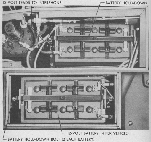
Unlike the M24 tank with its four 6-volt batteries, the M19 used four 12-volt batteries, with two on each side being connected in series to make a 24-volt electrical system. On each side, one battery was mounted in a compartment just above the front end of the fuel tank, and the other was housed in a box on the fender next to the other battery compartment. The right and left battery pairs were connected in parallel but were controlled by separate master switches, enabling one set to be excluded from the generating circuit if needed. (Picture from TM 9-757 Twin 40-mm Gun Motor Carriage M19.)
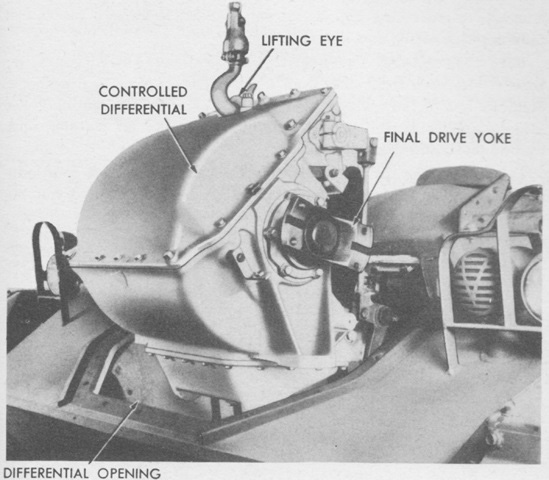
The controlled differential is being removed through the front opening. The differential gearing was of the spur type with a 1.92:1 maximum ratio, while the drive gearing was spiral bevel with a 2.62:1 ratio. Two brake rims were present, 15"x4.5" (38cm x 11cm), and these each had three brake linings of 13"x4" (33cm x 10cm). (Picture from TM 9-757 Twin 40-mm Gun Motor Carriage M19.)
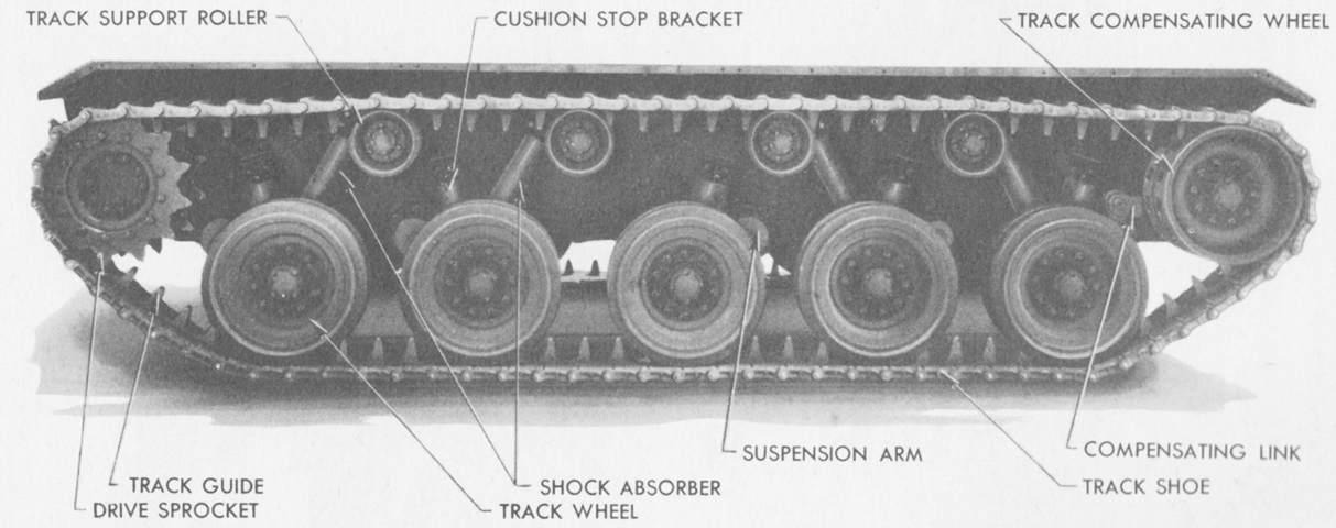
The increased wheel spacing and extra return roller compared to the light tank M24 are better seen here with the sand shields absent. (Picture from TM 9-757 Twin 40-mm Gun Motor Carriage M19.)
The turret is shown from the left. The complete gun mount weighed around 6,800lb (3,100kg). (Picture from TM 9-757 Twin 40-mm Gun Motor Carriage M19.)
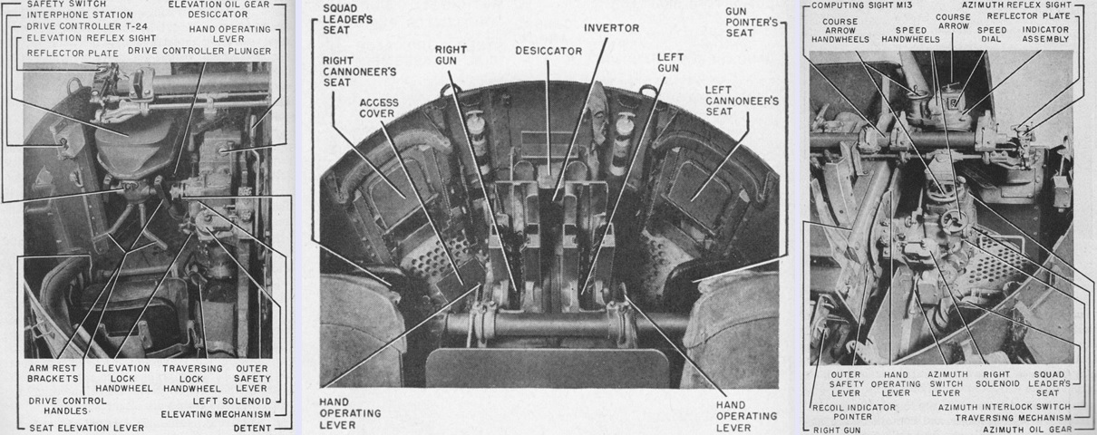
The left, rear, and right of the gun mount M4 are detailed in the left, center, and right, respectively. (Picture from FM 44-62 Service of the Piece, Twin 40-mm Gun Motor Carriage M19.)
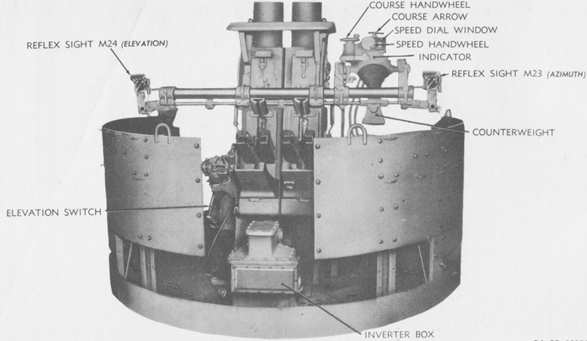
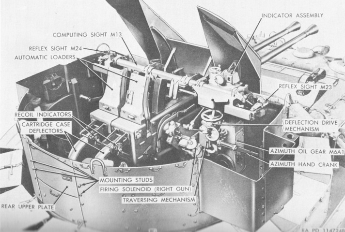
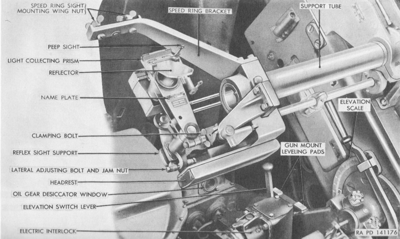
Two views of the gun mount from behind are provided, and on the right the assembly of the computing sight M13 can be seen. This sight included the indicator and reflex sight M23 for azimuth and the reflex sight M24 for elevation. The computing sight M13 was operated by the squad leader, while the gun pointer operated the reflex sight M24. An arrow was provided for setting the course of the target, and the target's estimated speed (up to 500mph [800kph]) was shown on a dial graduated in 25mph (40kph) intervals. As the course and speed were set into the computing sight, the sight mechanically calculated the line-of-sight of the telescopes in relation to the guns' bores, and automatically moved the telescopes to the correct deflections. The reflex sights were connected on their supports so that they moved in concert in both elevation and azimuth. Speed ring sights were stowed in case of failure of the computing sight. (Picture from TM 9-2300 Artillery Matériel and Associated Equipment and TM 9-757 Twin 40-mm Gun Motor Carriage M19.)
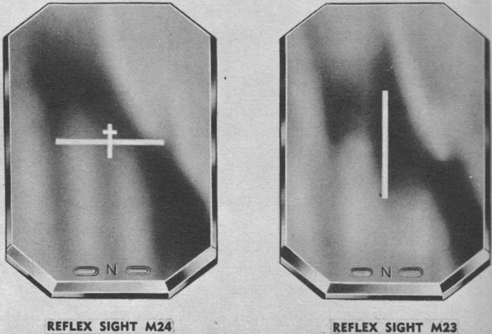
The reticles for the reflex sights are shown here. The M23 provided a thin vertical line, while the M24 had a horizontal line and a smaller vertical line. The elevation tracker of the crew was to keep the intersection of the large cross of the M24's reticle on the target. The M24's small cross was used for boresighting. (Picture from TM 9-761 Twin 40-mm Gun Motor Carriage M19A1.)
The turret is shown from the right. (Picture from TM 9-757 Twin 40-mm Gun Motor Carriage M19.)
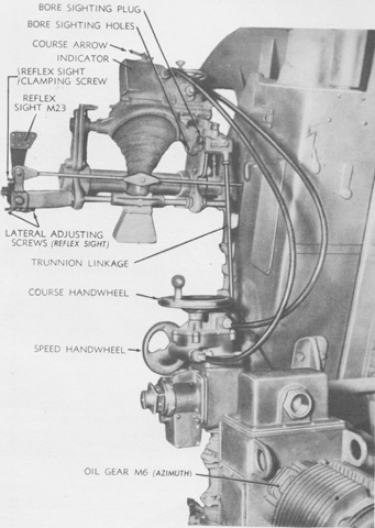
The front right side of the gun mount is highlighted in this picture. Speed and course handwheels were provided both on and below the indicator for operator convenience. (Picture from TM 9-757 Twin 40-mm Gun Motor Carriage M19.)
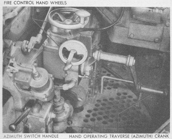
When using power traverse, the hand operating crank was removed and stowed. The azimuth switch handle was pushed down for power traverse and raised for manual traverse. The right cannoneer operated the manual traverse crank; if desired when this occurred, the squad leader could order the driver into the turret to take over the right cannoneer's other duties while he was occupied with azimuth tracking. (Picture from TM 9-757 Twin 40-mm Gun Motor Carriage M19.)
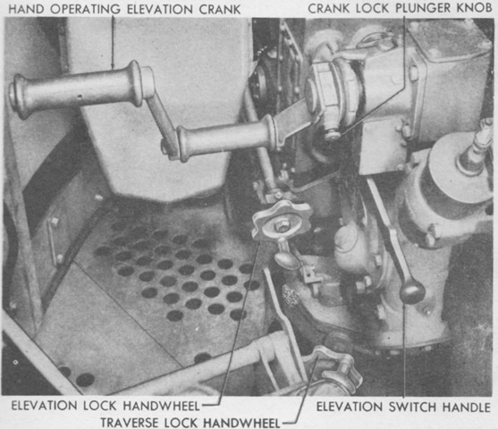
Similarly, the elevation gearing had a removable hand crank and a switch that was lowered for power elevation and raised for manual elevation. The gun pointer served as elevation tracker when manual elevation was being used. The elevation and traverse locks prevented unwanted movement during travel. (Picture from TM 9-757 Twin 40-mm Gun Motor Carriage M19.)
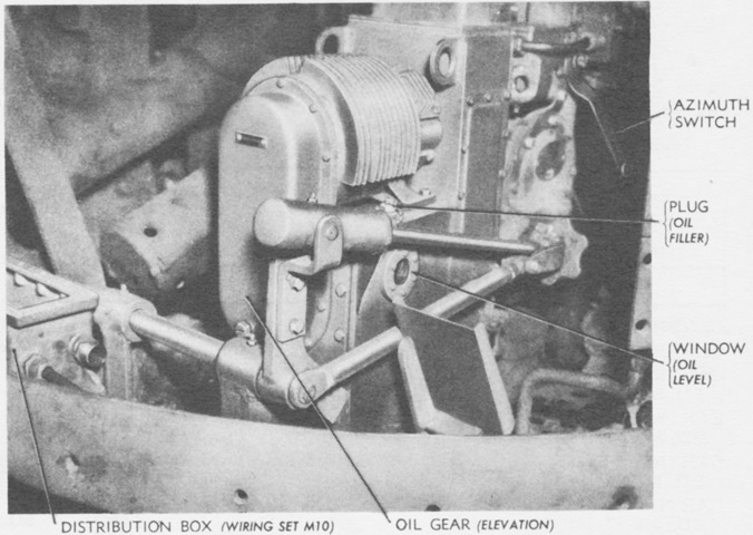
The oil gears M6 were part of the local control system M16, which also included the wiring set M10 and the drive controller M9. The oil gears converted electrical power into mechanical power for traverse and elevation; the wiring set carried electrical power; and the drive controller controlled the traverse, elevation, and firing of the guns. (Picture from TM 9-757 Twin 40-mm Gun Motor Carriage M19.)
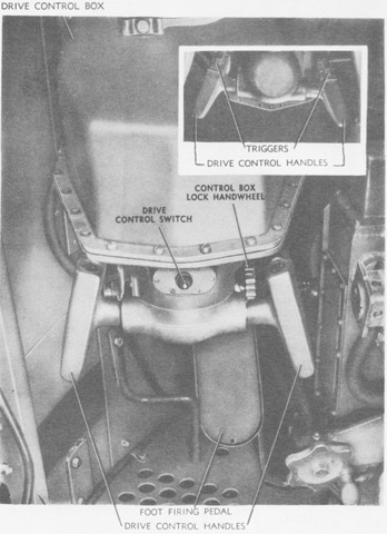
The drive controller could be lowered to be out of the way for manual operation or raised when powered operation was desired. The drive control handles allowed a single man to control the guns in traverse and elevation, and triggers allowed electrical firing of both guns. The foot firing pedal was used to fire the guns when manual power was being used. The handles were set so that sensitivity was increased as the mount speed increased, so that a given displacement made at a high mount speed would cause a greater effect than the same displacement at low mount speed. (Picture from TM 9-757 Twin 40-mm Gun Motor Carriage M19.)
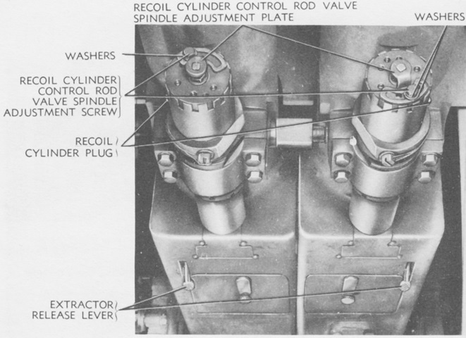
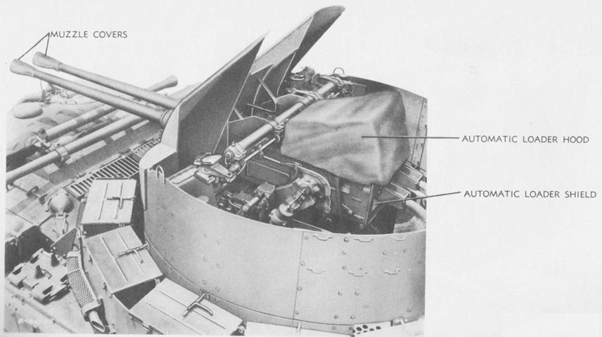
The guns' recoil mechanisms and extractor release levers are detailed here. The guns' outer safety levers had positions for single shot or automatic fire; each barrel assembly weighed around 296lb (134kg); and the dual gun weighed about 2,100lb (950kg). (Picture from TM 9-757 Twin 40-mm Gun Motor Carriage M19.)
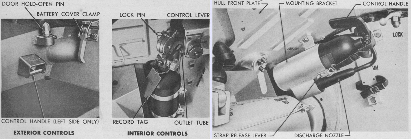
The fixed fire extinguisher system used a single 10lb (4.5kg) CO2 cylinder mounted on the left side of the bulkhead in the driving compartment, routed to the engine and fuel tank compartments. It was actuated by using the lever on the cylinder's control head or by an external handle just ahead of the left-side fender battery box. In addition, three 4lb (1.8kg) CO2 portable extinguishers were carried. One was stowed on the hull front plate ahead of the assistant driver, as seen on the right; the other two were on the gun mount. (Picture from TM 9-757 Twin 40-mm Gun Motor Carriage M19.)
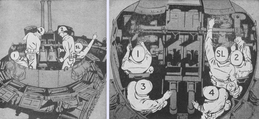
The gun crew is shown in position during power operation on the left and manual operation on the right. SL is the squad leader; 1 is the gun pointer; 2 is the right cannoneer; 3 is the left cannoneer; and 4 is the driver, who as mentioned could replace the right cannoneer when he manned the manual traverse control. (Picture from FM 44-62 Service of the Piece, Twin 40-mm Gun Motor Carriage M19.)
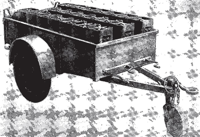
Each M19 was provided with an ammunition trailer M28, which was a standard 2-wheeled, 1-ton (910kg) cargo trailer modified with clamps to hold twenty 16-round ammunition chests M14. It was 142" (361cm) long overall with a 101" (257cm) long trailer body; 72" (180cm) wide overall; 55" (140cm) tall to the top of the ammunition containers; and ground clearance was 16½" (41.9cm). Net weight was 1,527lb (692.6kg), which increased to 2,352lb (1,067kg) with a camouflage net and empty ammunition containers and 3,783lb (1,716kg) with a camouflage net and full ammunition containers. The trailer came with a canvas cover to protect it from the dust and mud kicked up by the vehicle's tracks. (Picture from FM 44-62 Service of the Piece, Twin 40-mm Gun Motor Carriage M19.)
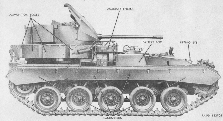
The M19A1 featured the addition of an auxiliary engine and generator that could provide electrical power to complement that produced by the main engines' generators. The auxiliary engine and generator could be run when the batteries were to be charged, when the current provided by the main engines' generators was insufficient for the demanded load, when auxiliary electrical equipment was needed while the main engines were off, or when the gun mount was to be operated. Note the tracks on this vehicle, which are reversed from their usual orientation. (Picture from TM 9-761 Twin 40-mm Gun Motor Carriage M19A1.)
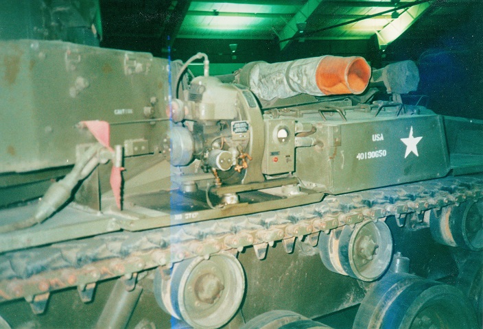
Bulges were added to the rear sides of the turrets, and the larger right-side bulge was used to mount radio equipment. The auxiliary engine's mounting position on the right fender precluded the usual placement of the right-side main engine exhaust pipe, so the main engine exhausts were combined and routed to the left under a guard. (Picture from TM 9-761 Twin 40-mm Gun Motor Carriage M19A1.)
The redesigned exhaust pipe and guard can be seen from this angle. (Picture from TM 9-761 Twin 40-mm Gun Motor Carriage M19A1.)
The auxiliary engine position and its exhaust pipe are visible here. (Picture from TM 9-761 Twin 40-mm Gun Motor Carriage M19A1.)
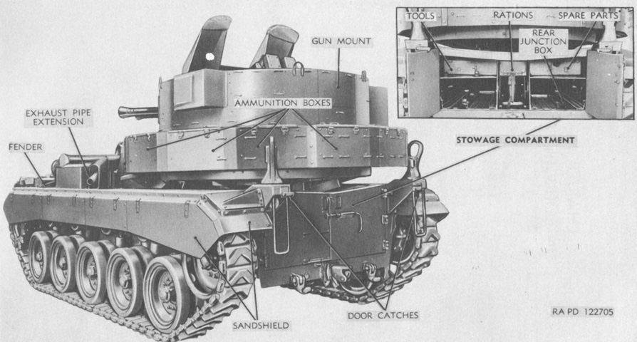
The interior of the stowage compartment is revealed. (Picture from TM 9-761 Twin 40-mm Gun Motor Carriage M19A1.)
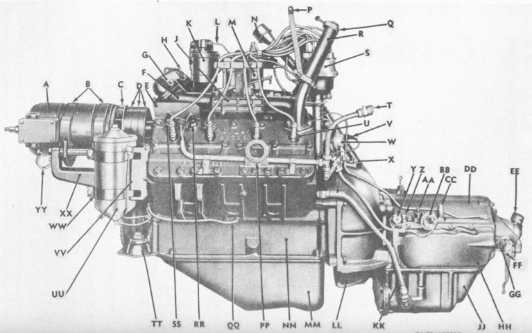
The opposite side of the engine and transmission are shown compared to the image above. A. Generator. B. Generator mounting clamp. C. Generator fan. D. Drive belts. E. Cable shield. F. Left exhaust manifold. G. Exhaust manifold connection. H. Manifold-to-connection screw. J. Choke heater. K. Engine crankcase air cleaner. L. Ventilating pipe (crankcase air cleaner to distributor). M. Carburetor. N. Transmission oil level indicator. P. Ground strap. Q. Hose clamp. R. Water hose. S. Distributor. T. Engine wiring cable conduit coupling. U. Spark plug. V. Cable nipple. W. Engine low oil pressure signal switch. X. Engine flywheel drain cover. Y. Transmission oil pressure regulator valve plug. Z. Transmission front band adjustment indicator rod cap. AA. Transmission brake bands adjusting screw. BB. Transmission low oil pressure warning signal switch. CC. Transmission rear band adjusting screw cap. DD. Transmission. EE. Transmission-to-transfer unit universal connection. FF. Transmission control valve manual operation lever. GG. Transmission manual shifter rod boot. HH. Transmission side cover. JJ. Transmission oil pan. KK. Oil line. LL. Engine flywheel lower housing. MM. Engine oil pan. NN. Crankcase. PP. Engine lifting ring. QQ. Engine-tappet-to-crankcase pipe. RR. Engine temperature signal unit. SS. Engine temperature signal switch. TT. Engine support cushion. UU. Oil filter. VV. Oil filter support. WW. Oil filter support strap. XX. Generator bracket. YY. Ground strap. (Picture from TM 9-761 Twin 40-mm Gun Motor Carriage M19A1.)
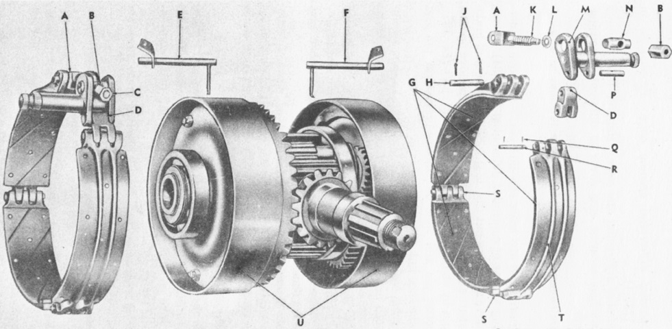
An exploded view of the differential and steering brakes is provided in this picture. A. Adjusting yoke. B. Adjusting nut. C. Brake operating shaft. D. Brake shoe link. E. Left brake drum lubricating tube. F. Right brake drum lubricating tube. G. Brake bands. H. Brake-shoe-to-yoke pin. J. Cotter pins. K. Adjusting yoke spring. L. Adjusting yoke spring washer. M. Brake operating shaft. N. Adjusting yoke pin. P. Operating shaft pin. Q. Cotter pin. R. Link-to-brake-shoe pin. S. Brake shoe pin. T. Brake shoe. U. Brake drum. (Picture from TM 9-761 Twin 40-mm Gun Motor Carriage M19A1.)
The transfer unit combined the power output of the two engines and provided two forward speed ranges (low and high) and one reverse. High range was used for smooth, level terrain, and low was intended for hill climbing or rough, sandy, or muddy terrain. The speed ranges for the transfer unit were all manually selected. A sliding clutch allowed one engine to be disengaged so that the vehicle could operate on a single engine. (Picture from TM 9-761 Twin 40-mm Gun Motor Carriage M19A1.)
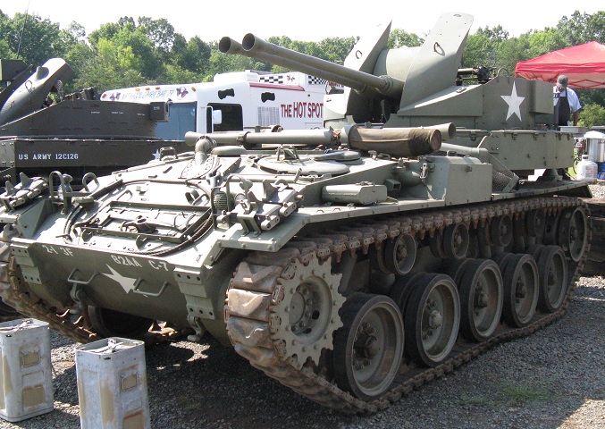
From this angle, the M19 and M19A1 are difficult to differentiate, but the revised engine exhaust pipe is visible.
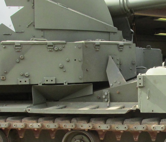
The auxiliary generator would be mounted on the right-hand fender behind the battery box, but it is absent on this vehicle. There are holes in the ammunition box facing us, however, that show where the generator's exhaust pipe and guard were mounted diagonally downward across the ammo box.
A closer view of the generator is provided here, and its presence shows how the original routing of the right-hand exhaust pipe was precluded.
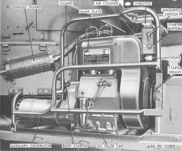
The Wisconsin engine model TFG and Eclipse-Pioneer generator were an integral unit. The engine was a 2-cylinder, 4-cycle, self-lubricating, constant-speed, air-cooled gasoline type governed at 2,700rpm. It could be started manually by a rope and starter sheave or electrically via the generator. The generator was rated at 28.5 volts. (Picture from TM 9-761 Twin 40-mm Gun Motor Carriage M19A1.)
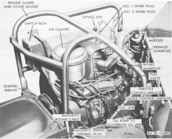
The right side of the auxiliary engine installation is shown here. The engine had a bore and stroke of 3.25" (8.26cm) each, and produced 11.3hp. (Picture from TM 9-761 Twin 40-mm Gun Motor Carriage M19A1.)
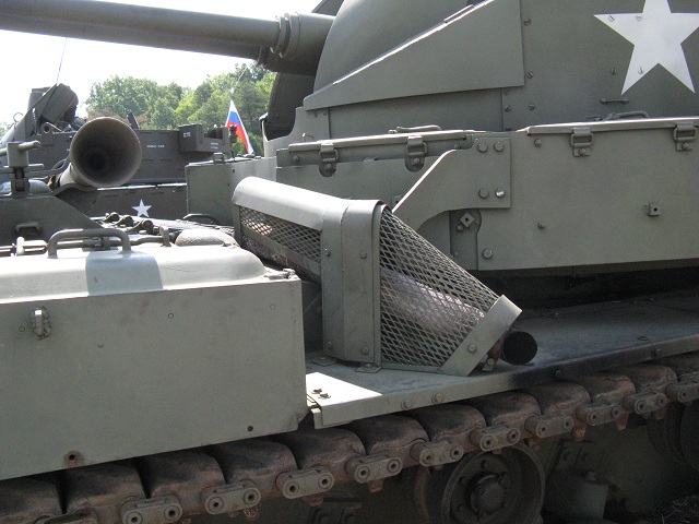
Details of the single exhaust exit and its guard are shown here. By contrast, the dual-exhaust of the M19 had a pipe connected to the ammunition stowage bins on each side of the turret.
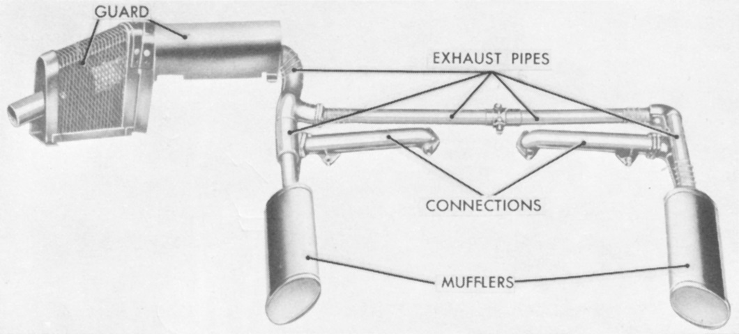
The revised main engine exhaust system is shown here removed from the vehicle. (Picture from TM 9-761 Twin 40-mm Gun Motor Carriage M19A1.)
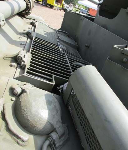
The revised engine deck is highlighted here. The engine compartment grille doors are between the turret and the spare barrels, and the guard for the engine exhaust pipe is pointing toward the lower right corner of the picture. A cover for a gasoline tank filler is at the bottom of the image, and a similar one could be found on the opposite side of the vehicle
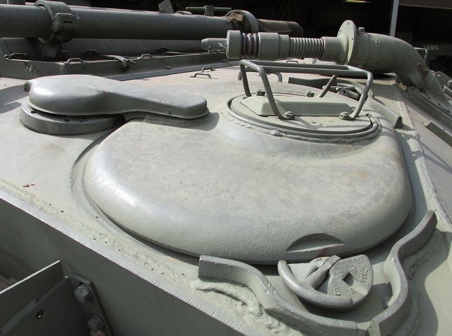
Details of the assistant driver's door and the front antenna mount can be seen here. Both drivers were provided with a periscope M6 in their hatches.
The driver's door is shown here locked in the open position. (Picture from TM 9-761 Twin 40-mm Gun Motor Carriage M19A1.)
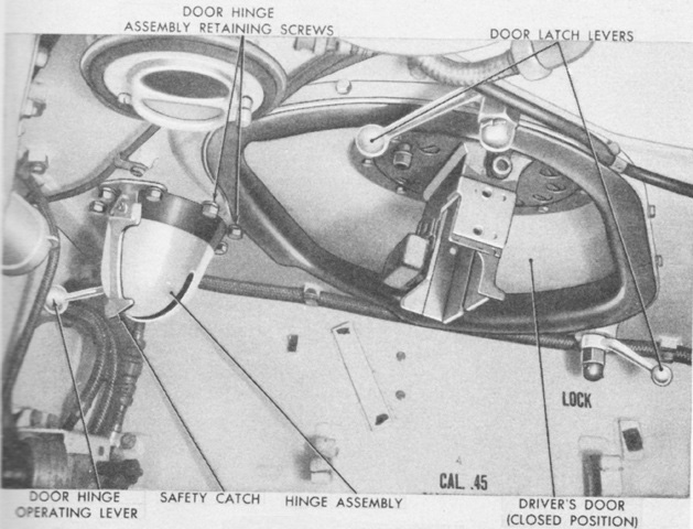
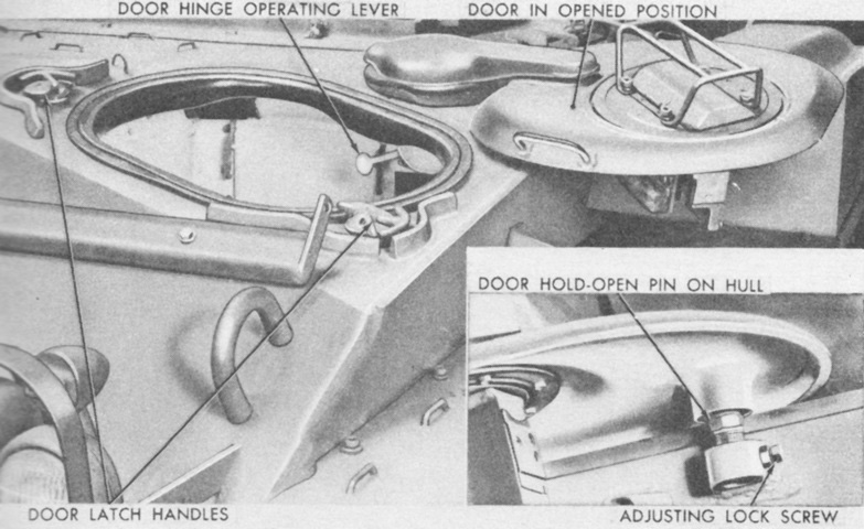
Interior controls for the driver's door are labeled in this image. (Picture from TM 9-761 Twin 40-mm Gun Motor Carriage M19A1.)
The left side of the turret is shown here. (Picture from TM 9-761 Twin 40-mm Gun Motor Carriage M19A1.)
Here is the opposite side of the turret. An antenna mount is attached to the front of the radio bulge on the turret's right side. (Picture from TM 9-761 Twin 40-mm Gun Motor Carriage M19A1.)
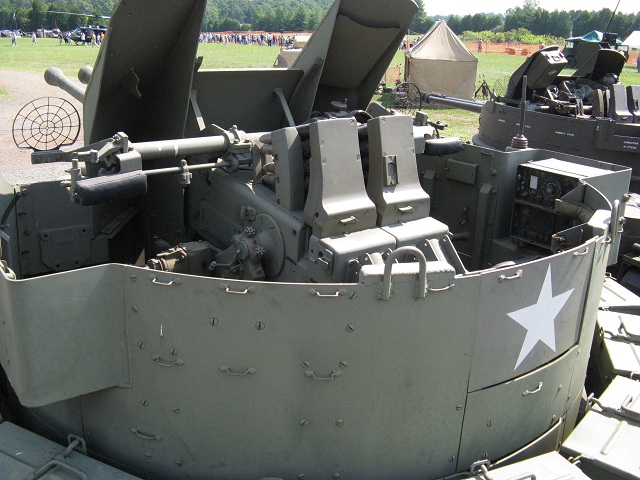
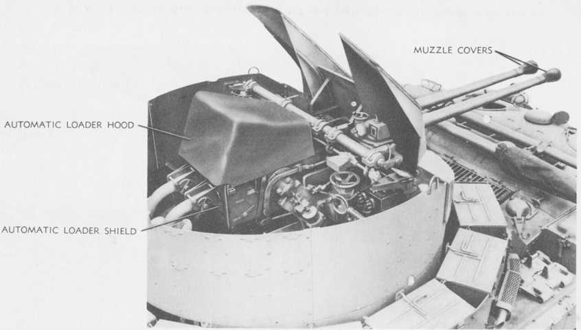
Some details of the turret interior can be gleaned from this image. A direct fire front speed ring sight is visible on each side of the gun shield, and the guns' automatic loaders occupy much of the space in the center of the turret. The bulges in the turret sides are apparent, and a radio is installed in the right-hand bulge. A packing case for the direct fire sights could be stowed in the cleft of the left-hand gun shield, but it is absent on this vehicle.
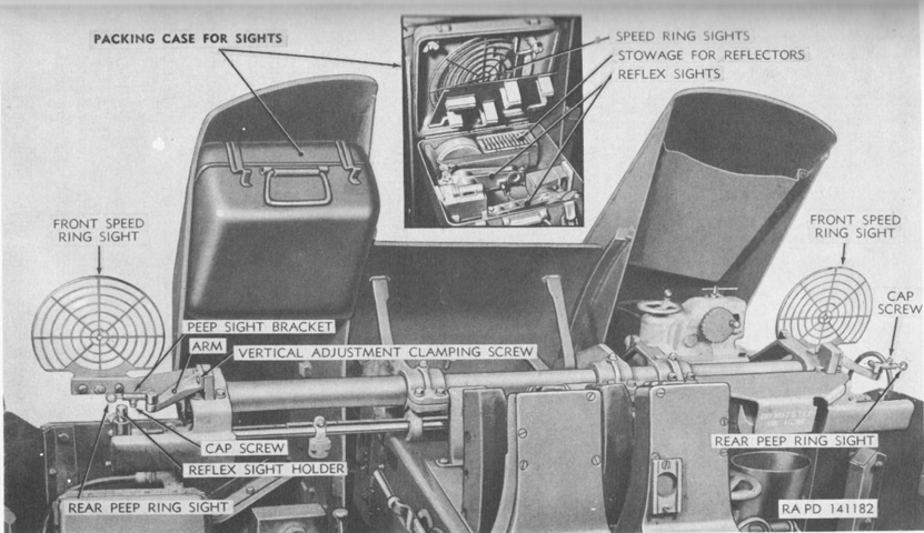
The mounting of the speed rings sights is illustrated in this picture. The sight packing case is shown stowed on the gun shield as well as open to reveal its load plan. (Picture from TM 9-761 Twin 40-mm Gun Motor Carriage M19A1.)
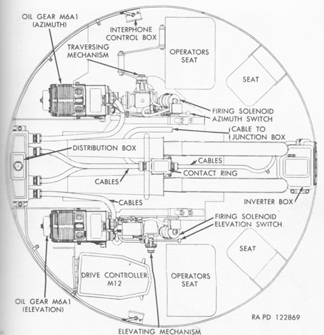
A schematic of the control system M16A1 is provided here. (Picture from TM 9-761 Twin 40-mm Gun Motor Carriage M19A1.)
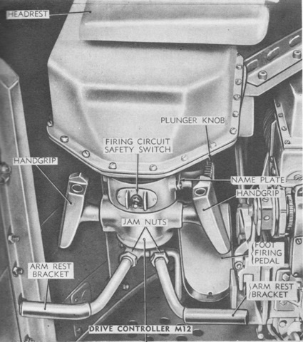
Parts of the M12 drive controller are labeled in this image. The arm rests enabled smoother tracking of targets. (Picture from TM 9-761 Twin 40-mm Gun Motor Carriage M19A1.)
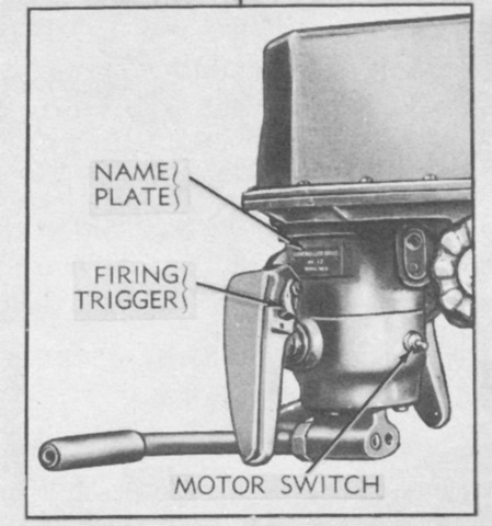
The firing triggers remained on the opposite face of the drive control handgrips. (Picture from TM 9-761 Twin 40-mm Gun Motor Carriage M19A1.)
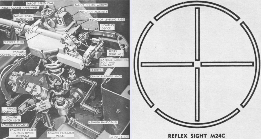
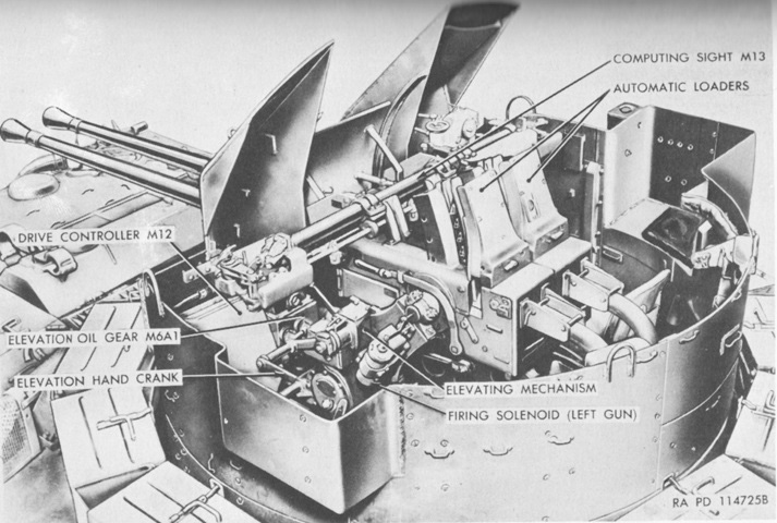
The sighting and fire control equipment on the azimuth side is shown here. The computing sight M13A1 could support the reflex sights M24C on both the elevation and traverse sides, as opposed to the computing sight M13.
As shown on the right, the M24C's reticle had vertical and horizontal aiming lines versus the separate reflex sights M23 and M24 used for azimuth and elevation, respectively, on the computing sight M13. (Picture from TM 9-761 Twin 40-mm Gun Motor Carriage M19A1.)
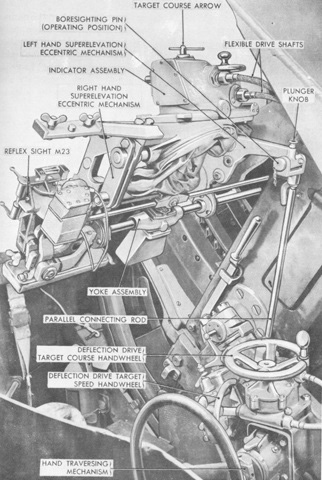
The deflection drive is labeled in this picture. (Picture from TM 9-761 Twin 40-mm Gun Motor Carriage M19A1.)
The mounting of the reflex sight M24 on the elevation side is shown here. (Picture from TM 9-761 Twin 40-mm Gun Motor Carriage M19A1.)
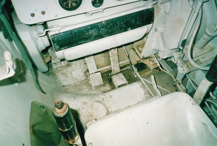
The left-hand driver's position was inherited from the M24. The accelerator pedal is on the right, and the neutral pedal is in the center. The steering levers flank the driver's seat, and the vehicle's data plate is just below the instrument panel. Visible on the instrument panel, from left to right, are two circuit breaker reset buttons, the left engine tachometer, and the ammeter. The clip to the driver's left was for stowage of a .45cal machine gun.
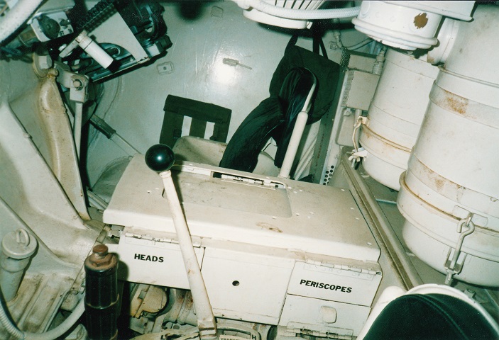
The drivers were separated by the controlled differential to the front, and the spare periscope and periscope head box sits atop the front main propeller shaft. The large black-tipped lever is the transmission unit shift control lever. The large cylinders in the rear of the driver's compartment are the engine carburetor air cleaners.
