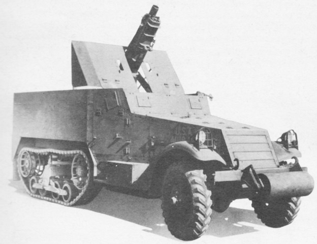
75mm Howitzer Motor Carriage T30.

The howitzer on this vehicle is at maximum elevation, and the hinge in the howitzer shield that allowed it to fold when not in use can be seen. The shield pictured is an early version; later vehicles were equipped with a shorter shield that extended more to the rear. This vehicle is still fitted with the large, fender-mounted headlights. (Picture from TM 9-2800 Standard Military Motor Vehicles.)
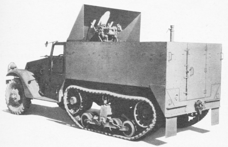
This rear view allows us to see the machine gun pedestal at the rear of the vehicle. (Picture from TM 9-710 Basic Half-Track Vehicles (White, Autocar, and Diamond T).)
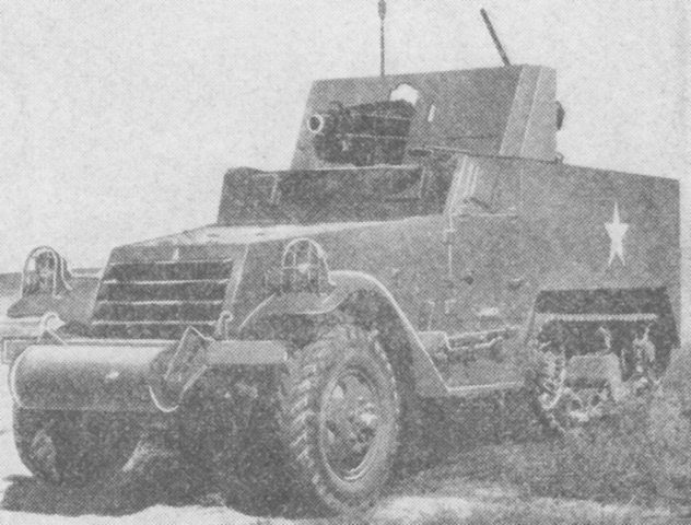
A revised howitzer shield is mounted on this vehicle. (Picture from FM 30-40 Military Intelligence Identification of United States Armored Vehicles.)
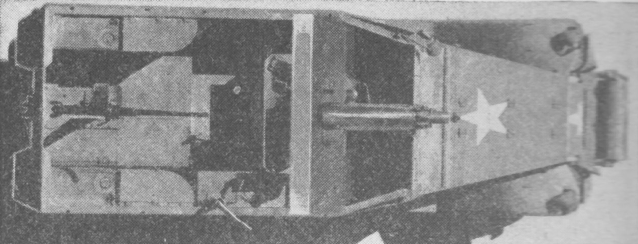
The redesigned shield featured a horizontal plate overtop of the howitzer. The .50cal machine gun is mounted on this machine. (Picture from FM 30-40 Military Intelligence Identification of United States Armored Vehicles.)
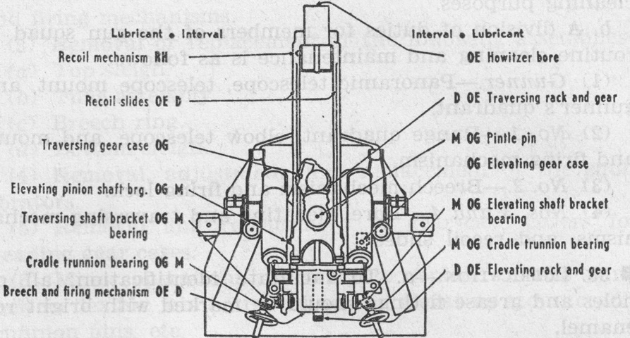
Details of the howitzer mount are sketched in this lubrication chart. The lubricants include heavy recoil oil (RH), crankcase engine oil (OE), and O.G. grease (OG). The "M" interval is monthly, and the "D" interval is undefined in the key. (Picture from FM 17-64 Service of the Piece, 75-mm Howitzer T-30, Self-Propelled.)
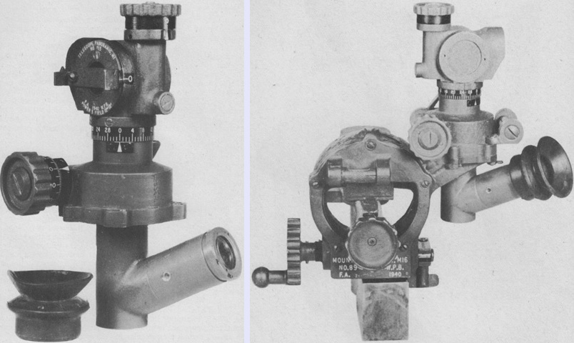
The panoramic telescope M1 is shown isolated on the left and installed in the telescope mount M16 on the right. The M1 was a 3x erect image device with a 12°12' field of view, and was used to lay the howitzer in azimuth. Its azimuth scale was graduated in mils from 0 to 32, and its azimuth micrometer was graduated in 1-mil increments from 0 to 100. The telescope's elbow slanted upward at 25°, and the telescope could also be rotated to suit the user's position. The telescope mount M16 provided leveling and cross-leveling mechanisms. (Picture from TM 9-2005 Ordnance Material - General, Volume V: Sighting and Fire-Control Equipment - General, Aircraft Cannon.)
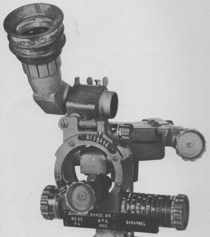
The elbow telescope M5 is mounted in the range quadrant M3. The M5 was a 3x device with a prism erecting system that produced a 90° elbow so that the user could face to the side while observing. Used to lay the howitzer in elevation during direct fire, the reticle was composed of the letter "N" representing the normal line of sight, and numbered long and short horizontal lines representing 400 to 3,000 yards (370 to 2,700m). The M5 had no separate mount, but was clamped to the top of the range quadrant M3, which was used to lay the howitzer in elevation during indirect fire. The M3 contained a cross-leveling mechanism, range-elevation mechanisms with range and elevation scales, and angle-of-site mechanisms with scales and an angle-of-site level vial. Each range drum was calibrated for a specific weapon, ammunition type, and propellant charge. (Picture from TM 9-2005 Ordnance Material - General, Volume V: Sighting and Fire-Control Equipment - General, Aircraft Cannon.)
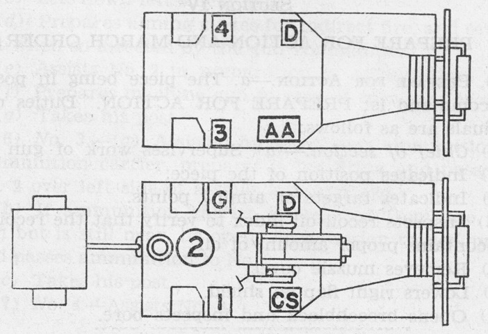
The mounted posts of the assault gun section are shown here. The T30, referred to as the assault gun, is shown towing an ammunition trailer, and a half-track personnel carrier M3 accompanies as an ammunition carrier. On the T30, the crew were the driver (D), chief of section (CS), gunner (G), and two cannoneers (1 and 2). The ammunition carrier was manned by a driver (D), ammunition agent (AA), and two more cannoneers (3 and 4). (Picture from FM 17-64 Service of the Piece, 75-mm Howitzer T-30, Self-Propelled.)
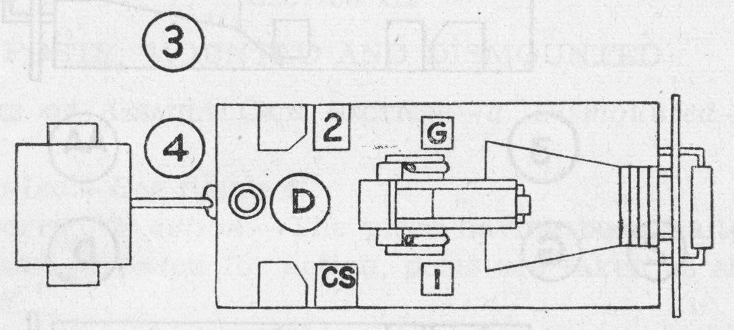
The action posts of the crew are shown here. The two cannoneers from the ammunition carrier would often remain with that vehicle, which could be used for perimeter defense or placed under cover to the rear. (Picture from FM 17-64 Service of the Piece, 75-mm Howitzer T-30, Self-Propelled.)