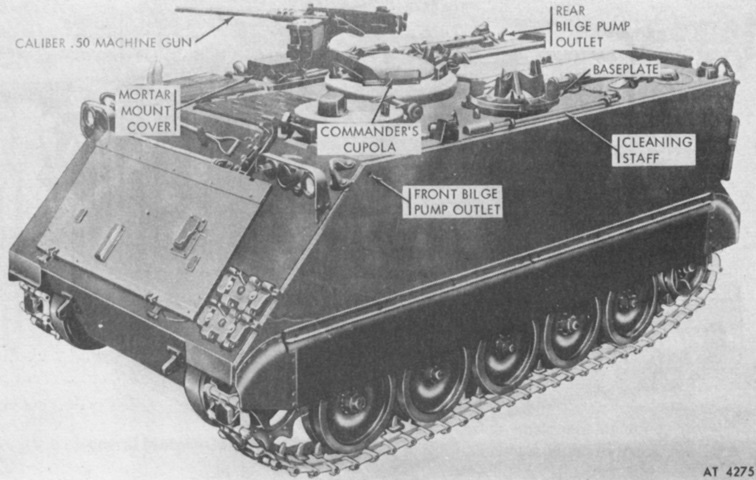
Armored Self-propelled 81mm Mortar Carrier M125A1.
The round rear mortar hatch was common to the 107mm self-propelled mortar M106A1. Stowage of the mortar ground assemblies was different between the two machines, however. (Picture from TM 43-0001-31.)
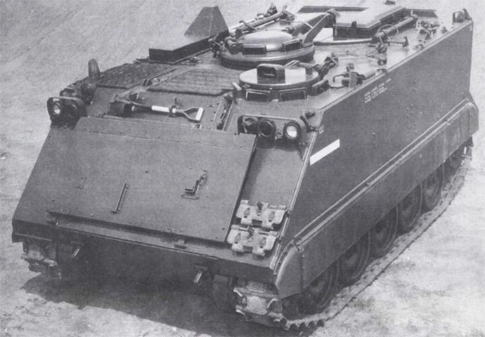
An extra stowage box can be seen on the mortar hatch. (Picture from TM 55-2350-224-14.)
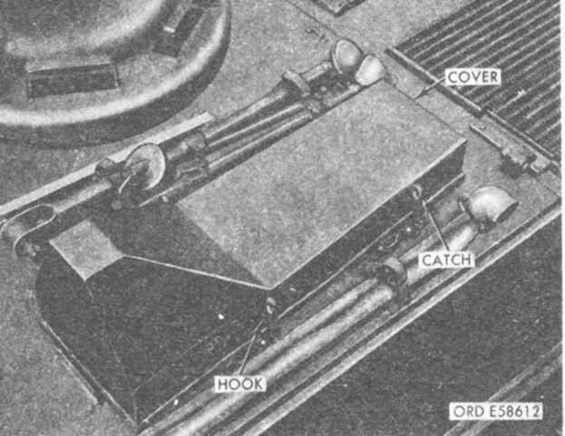
The mortar mount was stowed on the carrier roof to the right of the commander's cupola. It was protected by a cover when secured. (Picture from TM 9-2300-257-10.)
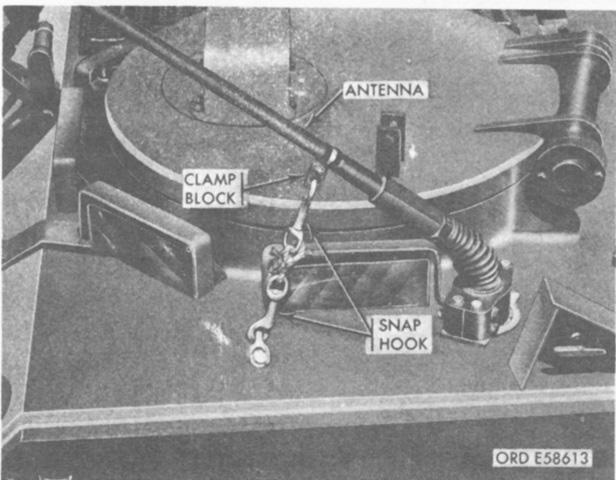
Since, in contrast to the 107mm mortar found in the M106, the 81mm mortar was provided with 360° traverse, a tiedown rope was provided to secure the radio antenna out of the line of fire for the mortar. The tiedown pulled the antenna to the front, past the driver's hatch as illustrated. (Picture from TM 9-2300-257-10.)
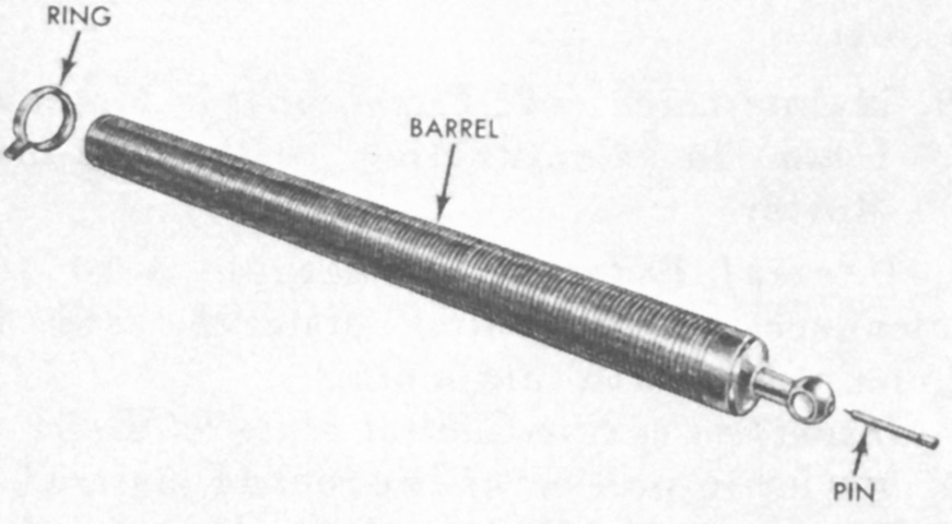
The 81mm mortar M29 or M29A1 consisted of a barrel, firing pin, and barrel ring. The barrel was threaded on the exterior; the first 17" (43cm) of threads were shallower than those on the remainder of the tube, which were taller with three threads occurring per inch (2.5cm). The mortar bipod yoke slid over the shallow threads, while the barrel ring was used on the uppermost 5" (20cm) of the full-depth threads. Maximum range was approximately 4,000 yards (3,600m), and maximum rate of fire using M362 high-explosive and M370 white phosphorus ammunition with charge eight (i.e., full charge) was 12 rounds per minute for 2 minutes followed by 3 rounds per minute sustained. (Picture from TM 9-2300-257-10.)
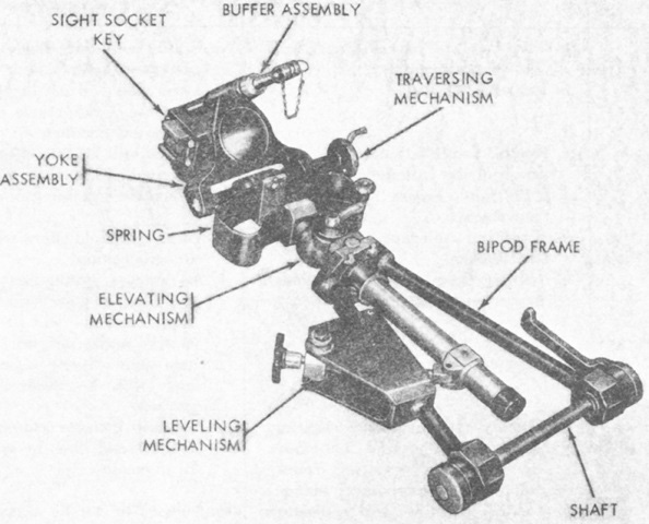
The upper end of the bipod assembly attached to the elevating mechanism housing, and the lower end to the mortar turntable. The buffer assembly attached to the barrel ring of the mortar tube. (Picture from TM 9-2300-257-10.)
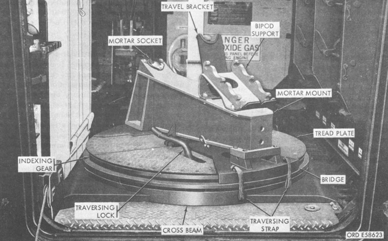
The mortar turntable is shown here. It was traversed by raising the traversing lock handle and then pulling on one of the traversing straps, two of which were attached to both the front and rear of the turntable. The traversing lock handle was then lowered until it automatically engaged with the teeth of the indexing gear. There were 128 teeth, yielding an interval of 50 mils between each tooth. The mortar bipod traversing gear was used for finer adjustments. (Picture from TM 9-2300-257-10.)
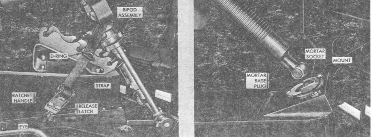
The mortar was secured for travel by a tiedown strap with a ratchet that hooked into an eye on either side of the mortar mount and then looped around bipod assembly elevating mechanism below the springs. On the right, the mortar socket is shown accepting the mortar base plug. The base plug was spherical with a flat surface on each side, and the mortar socket was U-shaped. When the plug was inserted into the socket, the mortar was turned 90° in either direction to lock the plug into the socket. (Picture from TM 9-2300-257-10.)
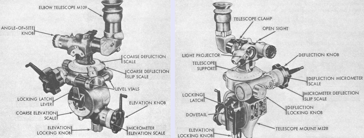
The sightunit M53, shared with the M106, consisted of the telescope mount M128 and elbow telescope M109 secured together for operation. The elbow telescope was 4x magnification with a 10° field of view, and had a cross or lined mil-scale reticle with graduations on the vertical and horizontal lines every 5 mils from 5 to 85 mils that were numbered every 10 mils in all four quadrants on both center lines. The eyepiece could be locked vertically or to either side. (Picture from TM 9-2300-257-10.)
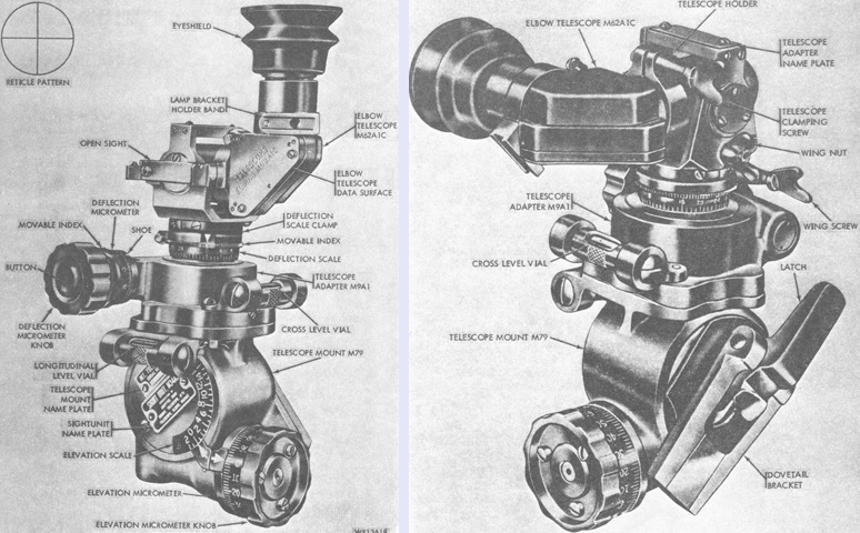
The sight unit M34A2, also common to the M106, consisted of the elbow telescope M62A1C, the telescope adapter M9A1, telescope mount M79, and a cross-level vial. The M62A1C was a 3x unit with a 12°12' field of view. (Picture from TM 9-2300-257-10.)
