8" Self-propelled Howitzer M55.
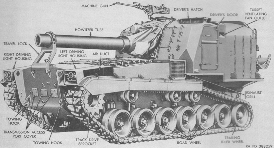
The M55 shared its hull, turret, and automotive components with the 155mm self-propelled gun M53, with differences related to their respective ordnances. The entire crew was housed in the large turret at the rear. (Picture from TM 9-2350-210-12 Operation and Organizational Maintenance 155-mm Self-propelled Gun Cannon M52 (T97) and 8-inch Self-propelled Howitzer Cannon M55 (T108).)

The turret rear had upper and lower doors, and when the recoil spade was stowed the lower door was blocked. An empty pioneer tool rack is on the turret's right rear corner. The vertical skirts hinged to the fenders were omitted after vehicle number 388. (Picture from TM 9-2350-210-12 Operation and Organizational Maintenance 155-mm Self-propelled Gun Cannon M52 (T97) and 8-inch Self-propelled Howitzer Cannon M55 (T108).)
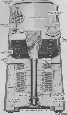
The engine and transmission were toward the front of the vehicle, with the air grille decking above. Outboard of the engine compartment were watertight stowage boxes. The driver was at the front left corner of the turret, with the gunner on the opposite side of the howitzer. The commander was seated behind the gunner. (Picture from TM 9-2350-210-12 Operation and Organizational Maintenance 155-mm Self-propelled Gun Cannon M52 (T97) and 8-inch Self-propelled Howitzer Cannon M55 (T108).)
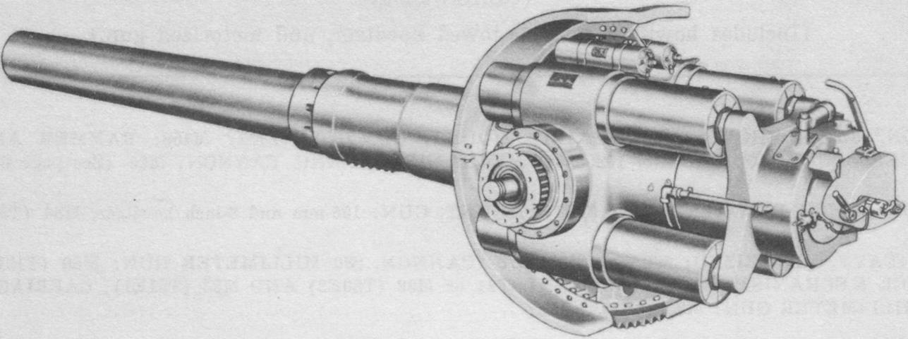
The 8" howitzer M47 is shown in the 155mm and 8" gun mount M86. The howitzer was principally built up from the firing lock, breechblock counterbalance assembly, breech mechanism group, and gun tube and breech ring group. The mount included the hydrospring recoil mechanism and replenisher assemblies and the cradle group. The tube was supported and aligned in the mount by finish-machined bearing surfaces on the tube's rear half. A torque key in the lower front portion of the cradle prevented rotation of the tube. The howitzer weighed 6,120lb (2,780kg), with the tube comprising 4,777lb (2,167kg) of that. The cannon was 216¾" (550.55cm) long from the muzzle to the rear face of the firing lock hammer, and its tube's estimated accuracy life was 6,000 rounds. The mount weighed 4,800lb (2,200kg), and the recoil mechanism's four recoil cylinders and replenisher assembly contained 25 gallons (95L) of fluid. (Picture from TM 9-500 C3 Data Sheets for Ordnance Type Materiel.)
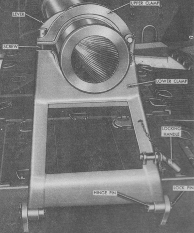
The shorter 8" ordnance necessitated a travel lock that was bent back toward the turret instead of the straighter device found on the M53's longer gun. The travel lock was secured in the raised or lowered position by a locking handle that engaged lugs welded to the lower clamp and the hull. The clamps were locked together by a lever-operated screw. (Picture from TM 9-2350-210-12 Operation and Organizational Maintenance 155-mm Self-propelled Gun Cannon M52 (T97) and 8-inch Self-propelled Howitzer Cannon M55 (T108).)
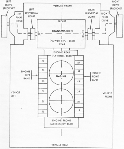
The position and nomenclature for the front-mounted powerplant is described in this sketch. Despite the engine's orientation in the hull, the flywheel end at the transmission was considered the rear of the engine and the accessory end was considered as the front. The engine's left and right sides were determined by looking at the engine from the accessory end. (Picture from TM 9-2350-210-12 Operation and Organizational Maintenance 155-mm Self-propelled Gun Cannon M52 (T97) and 8-inch Self-propelled Howitzer Cannon M55 (T108).)
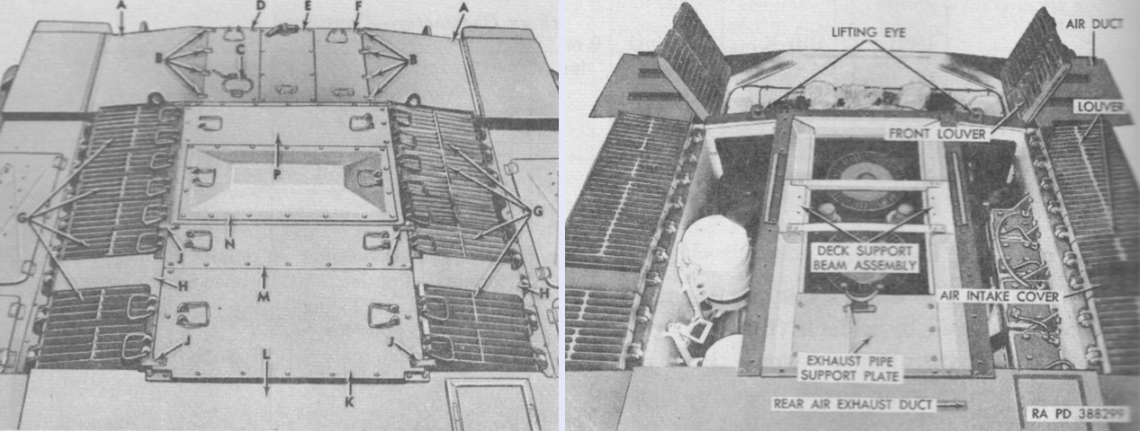
The top deck is shown closed on the left and with all louvres open and the engine muffler removed on the right. The legend for the left image is: A. Air duct cover. B. Cover clamp. C. Transmission oil filler cover. D. Transmission left cover. E. Transmission center cover. F. Transmission right cover. G. Louver. H. Air intake cover. J. Locking bar. K. Engine rear cover. L. Rear air exhaust duct. M. Muffler rear cover. N. Muffler intermediate cover. P. Muffler front cover. (Picture from TM 9-2350-210-12 Operation and Organizational Maintenance 155-mm Self-propelled Gun Cannon M52 (T97) and 8-inch Self-propelled Howitzer Cannon M55 (T108).)
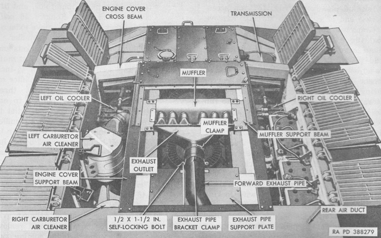
Another view of the open deck is provided, but with the muffler in place. (Picture from TM 9-2350-210-12 Operation and Organizational Maintenance 155-mm Self-propelled Gun Cannon M52 (T97) and 8-inch Self-propelled Howitzer Cannon M55 (T108).)
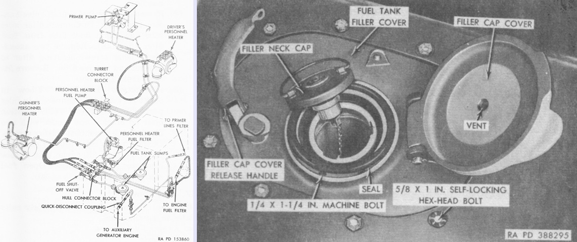
A schematic of the fuel system is drawn at the left. Two fuel tanks were housed in insulated, waterproof compartments behind the engine compartment. Each tank had its own filler, one of which is illustrated on the right. (Picture from TM 9-2350-210-12 Operation and Organizational Maintenance 155-mm Self-propelled Gun Cannon M52 (T97) and 8-inch Self-propelled Howitzer Cannon M55 (T108).)
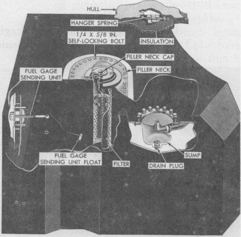
The fuel tanks were collapsible, neoprene-impregnated canvas assemblies, and this cutaway view reveals interior equipment. The fuel tanks were only interconnected at the fuel shutoff valve and needed to be filled separately. Each tank was secured to the top of its compartment by eight hanger springs. The left and right tanks were not interchangeable. (Picture from TM 9-2350-210-12 Operation and Organizational Maintenance 155-mm Self-propelled Gun Cannon M52 (T97) and 8-inch Self-propelled Howitzer Cannon M55 (T108).)
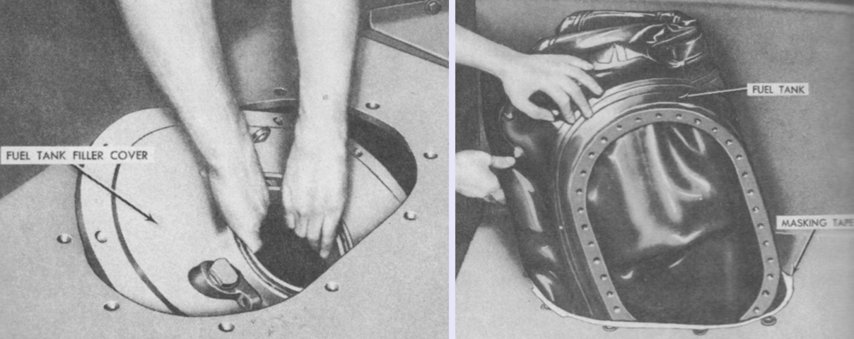
One of the collapsible fuel tanks is seen in the process of being removed. The fuel tank filler covers were fastened to the top of the hull with ten self-locking hex head bolts, and the filler neck attached to the tank with thirty-six self-locking hex head bolts, all of which needed to be removed in order to take the fuel tank out of the vehicle. (Picture from TM 9-2350-210-12 Operation and Organizational Maintenance 155-mm Self-propelled Gun Cannon M52 (T97) and 8-inch Self-propelled Howitzer Cannon M55 (T108).)
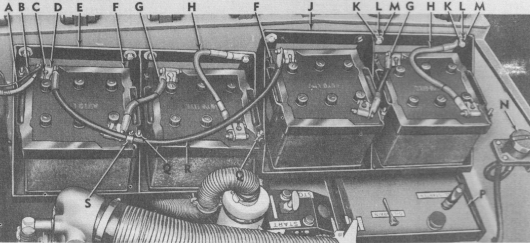
Four 12-volt lead-acid batteries were arranged in two sets on the right of the engine compartment above the auxiliary engine and generator, with each set comprised of two batteries connected in series. The two sets were then connected in parallel to make the series-parallel bank for the 24-volt electrical system. A. Master relay harness (no. 81). B. Circuit breaker harness (no. 459B). C. Battery positive terminal post. D. Battery terminal clamp. E. Front battery box. F. Battery retainer clamp. G. Interconnecting cable harness. H. Ground harness (no. 7). J. Rear battery box. K. ½ x 1¾ in. (1.3cm x 4.45cm) hex-head bolt. L. ½ in. (1.3cm) lock washer. M. ½ in. (1.3cm) flat washer. N. Slave receptacle connector. P. Auxiliary generator and engine. Q. ⅜ in. (.953cm) hex nut. R. Positive harness (no. 68). S. Cable support bracket. (Picture from TM 9-2350-210-12 Operation and Organizational Maintenance 155-mm Self-propelled Gun Cannon M52 (T97) and 8-inch Self-propelled Howitzer Cannon M55 (T108).)
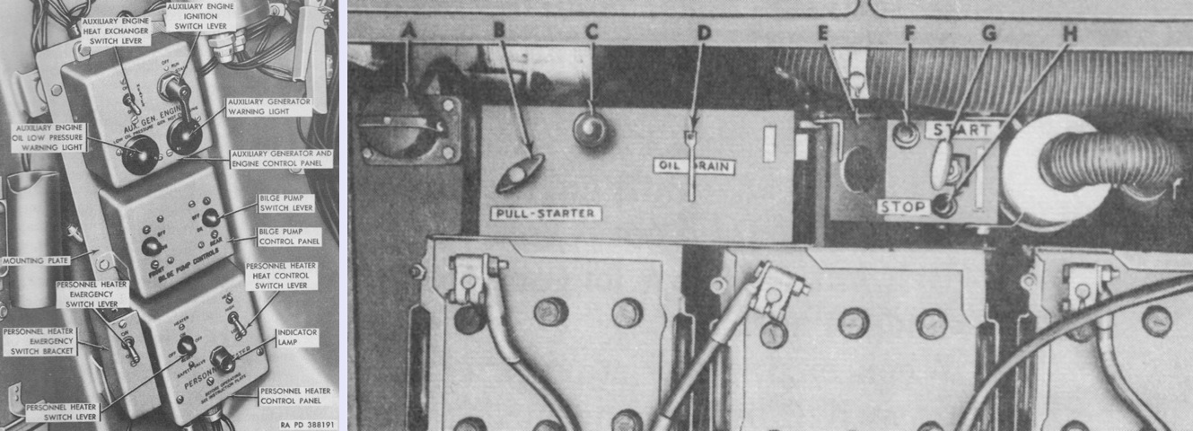
The driver was provided with controls for the auxiliary generator and engine, bilge pump, and a personnel heater. The auxiliary generator and engine are seen in the right image installed in the right rear of the engine compartment; these formed an integral unit weighing 386lb (175kg) dry. The generator was a Delco Products model A-8585 Type II shunt wound, automatic unit rated for 300 amperes, 8.4 kilowatt output, and a regulator setting of 28 volts. The generator's speed with no load was 3,250rpm, and at full load was 3,100rpm. The engine could be started electrically from both the turret and engine compartment, and a manual pull starter cable was provided if the battery system was not functioning. The legend for the right image is: A. Slave receptacle connector. B. Pull starter handle. C. Oil dip stick. D. Oil drain valve handle. E. Upper air duct damper valve handle. F. Start button switch. G. Throttle-choke control handle. H. Stop switch button. (Picture from TM 9-2350-210-12 Operation and Organizational Maintenance 155-mm Self-propelled Gun Cannon M52 (T97) and 8-inch Self-propelled Howitzer Cannon M55 (T108).)
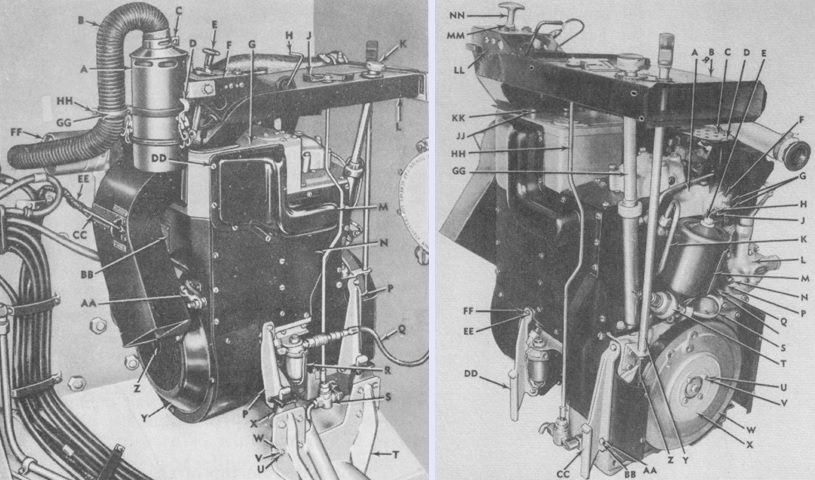
The auxiliary engine was a General Motors A-41-1 air-cooled, 4 cycle, 1-cylinder gasoline unit producing 14.5hp. Bore and stroke were 3⅝" and 4" (9.208cm and 10cm), respectively, for a displacement of 41in³ (670cm³). It was 29-3/16" (74.1363cm) tall and 16-13/16" (42.7038cm) wide, with a 6.6:1 compression ratio. Speed with no load was 3,250rpm, while speed with full load was 3,100rpm. The fan end of the engine was considered the rear of the engine despite being installed towards the front of the vehicle, and the gear case end was considered the front of the engine. Above, the assembly is seen from the right rear on the left and from the front on the right. The legend for the left image is: A. Air cleaner. B. Air cleaner intake duct. C. Duct clamp. D. Quick-release fasteners. E. Throttle-choke control handle. F. Control handle mounting bracket. G. Heat exchanger. H. Upper air duct damper valve handle. J. Oil drain valve handle. K. Oil dip stick. L. Upper exhaust air duct. M. Exhaust manifold cover. N. Engine right panel. P. Engine support bracket. Q. Fuel filter line. R. Fuel filter. S. Oil drain valve. T. Mount. U. 5/16 x ¾ in. (.7938cm x 1.9cm) hex-head cap screw. V. 5/16 in. (.7938cm) hex nut. W. 5/16 in. (.7938cm) lock washer. X. Engine support. Y. Rear shroud panel. Z. Fan hub. AA. Ground cable (no. 63). BB. Name plate. CC. Rear exhaust air duct damper valve handle. DD. ¼ x ½ in. (.64cm x 1.3cm) assembled-washer screw. EE. Battery cable (no. 64). FF. Air intake silencer. GG. Duct support clamp. HH. No. 10 x 1 in. (2.5cm) machine screw.
The legend for the right image is: A. Carburetor intake elbow. B. Upper exhaust air duct. C. Carburetor guard. D. ¼ x ½ in. (.64cm x 1.3cm) assembled-washer screw. E. Oil filter cover. F. Intake elbow thermostat cover. G. Intake elbow thermostat terminals. H. No. 10 lock washer. J. No. 10 x 7/16 in. (1.111cm) machine screw. K. Crankcase oil tube. L. Auxiliary engine governor. M. Oil filter. N. ¼ x 1-3/16 in. (.64cm x 3.0163cm) fillister-head machine screw. P. ¼ in. (.64cm) lock washer. Q. ¼ x 1¾ in. (.64cm x 4.45cm) self-locking nut. R [unlabeled]. 9/32 in. (.71438cm) flat washer. S. Oil pressure warning light switch tube. T. Oil pressure warning light switch. U. ¼ in. (.64cm) lock washer. V. ¼ x ⅝ in. (.64cm x 1.59cm) hex-head cap screw. W. Starting pulley. X. Inspection cover. Y. Pull starter cable guide tube. Z. Pull starter cable. AA. 5/16 in. (.7938cm) lock washer. BB. 5/16 x ⅞ in. (.7938cm x 2.22cm) hex-head cap screw. CC. Front engine support bracket. DD. Rear engine support bracket. EE. ¼ x ⅞ in. (.64cm x 2.22cm) hex-head cap screw. FF. ¼ in. (.64cm) lock washer. GG. Oil filter extension tube. HH. Oil drain valve control rod. JJ. ¼ in. (.64cm) lock washer. KK. ¼ x ½ in. (.64cm x 1.3cm) hex-head cap screw. LL. Throttle-choke control mounting bracket. MM. Throttle-choke control cable nut. NN. Throttle-choke control handle. (Picture from TM 9-2350-210-12 Operation and Organizational Maintenance 155-mm Self-propelled Gun Cannon M52 (T97) and 8-inch Self-propelled Howitzer Cannon M55 (T108).)
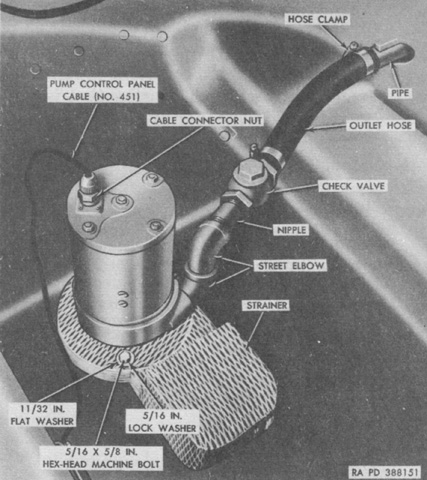
M55s up to serial number 116 and M53s up to number 242 featured a centrifugal-type bilge pump mounted on the turret support compartment floor. The pump's rate of flow was 50 gallons/minute (190L/min), and fluid was discharged through the rear of the hull via a hose. Despite the bilge pump control panel having switches for front and rear pumps, only the right-hand switch was active since the vehicle carried the single pump. (Picture from TM 9-2350-210-12 Operation and Organizational Maintenance 155-mm Self-propelled Gun Cannon M52 (T97) and 8-inch Self-propelled Howitzer Cannon M55 (T108).)
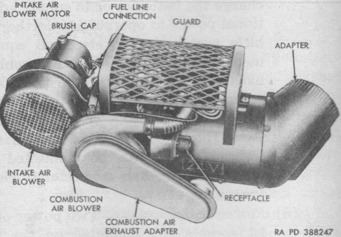
Two Stewart-Warner model 978M-H24 gasoline-burning personnel heaters were mounted in the turret, one in the driver's area and the second in the gunner's area. A personnel heater control panel was found under the driver's bilge pump control panel, and a second control panel for the gunner's heater was attached to the turret wall to the commander's right. (Picture from TM 9-2350-210-12 Operation and Organizational Maintenance 155-mm Self-propelled Gun Cannon M52 (T97) and 8-inch Self-propelled Howitzer Cannon M55 (T108).)
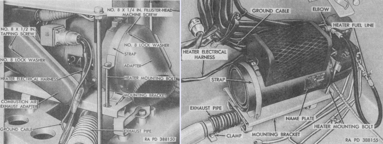
The heaters are installed above, with the gunner's heater on the left and the driver's on the right. The heaters each used 1 gallon (3.8L) of gasoline every 4 hours in high heat mode, and 1 gallon (3.8L) every 8 hours in low heat mode. (Picture from TM 9-2350-210-12 Operation and Organizational Maintenance 155-mm Self-propelled Gun Cannon M52 (T97) and 8-inch Self-propelled Howitzer Cannon M55 (T108).)

Fuel was supplied to the personnel heaters and to the driver's primer pump through the turret connector block seen here, which in turn was fed from the hull connector block, which also directed fuel to the main and auxiliary engines. A. Turret connector block-to-primer pump line. B. Primer pump-to-turret connector block line. C. Elevating pinion. D. Personnel heaters fuel line. E. Throttle master cylinder-to-turret connector block hydraulic line. F. Left personnel heater fuel line. G. ⅜ x 1½ in. (.935cm x 3.8cm) machine bolt. H. ⅜ in. (.953cm) lock washer. J. Turret connector block. K. Turret connector block-to-hull connector block hydraulic hose. L. Turret connector block-to-hull connector block fuel hose. M. Turret connector block mount. N. Stop light switch. P. Brake master cylinder-to-turret connector block line. (Picture from TM 9-2350-210-12 Operation and Organizational Maintenance 155-mm Self-propelled Gun Cannon M52 (T97) and 8-inch Self-propelled Howitzer Cannon M55 (T108).)
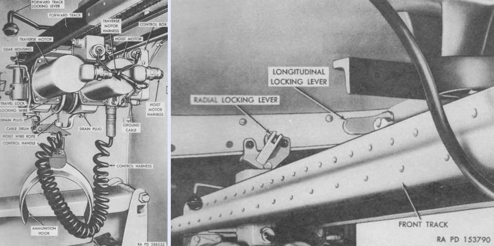
Thanks to the increased weight of the 8" howitzer compared to 155mm gun ammunition (e.g., the 8" high-explosive projectile M106 weighed 200.9lb [91.13kg] versus the 155mm high-explosive projectile's 95.90lb [43.50kg]), the M55 was provided with an electrically-powered ammunition hoist mounted on the turret roof. This was used to upload projectiles into the vehicle and also place them on the rammer trough. It was composed of a two-motored hoist mechanism that moved along a pivoting two-section track. Pushbuttons were provided for up, down, forward, and backwards movement. The hoist moved along the tracks by a drive sprocket that meshed with hoist traverse chains secured to the undersides of the track sections. The two sections of track could be unlocked from each other, and the forward track could also be unlocked longitudinally and radially in order to swing projectiles from the stowage rack onto the rammer trough. (Picture from TM 9-2350-210-12 Operation and Organizational Maintenance 155-mm Self-propelled Gun Cannon M52 (T97) and 8-inch Self-propelled Howitzer Cannon M55 (T108).)
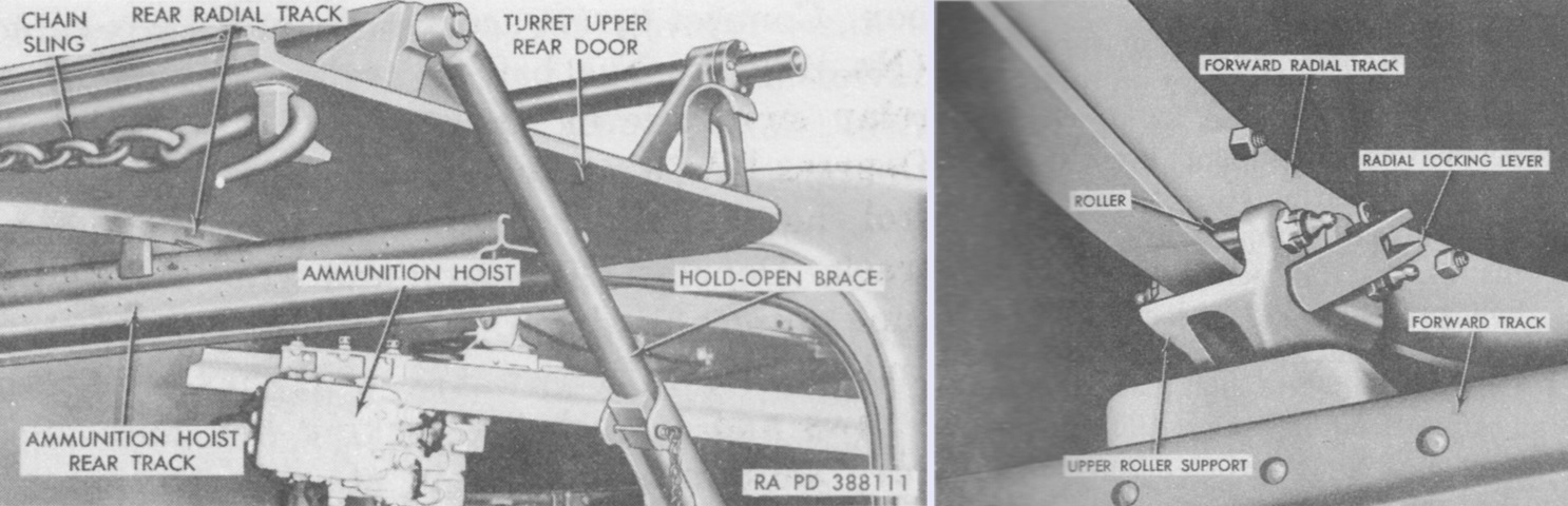
As seen on the left, the rear track of the ammunition hoist was on the turret upper rear door and was stowed crosswise when not in use. When locked to the front track, the rear track permitted the ammunition to clear the turret lower door when being loaded aboard the vehicle. Support rollers for the forward track are illustrated on the right. (Picture from TM 9-2350-210-12 Operation and Organizational Maintenance 155-mm Self-propelled Gun Cannon M52 (T97) and 8-inch Self-propelled Howitzer Cannon M55 (T108).)
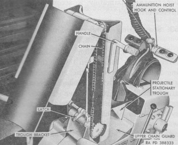
Operation of the M55's rammer trough was similar to that of the M53's: it was unfolded into the ramming position by pulling the handle out of the detent in the trough and then pushing it forward. The control buttons for the ammunition hoist can be seen behind the trough. (Picture from TM 9-2350-210-12 Operation and Organizational Maintenance 155-mm Self-propelled Gun Cannon M52 (T97) and 8-inch Self-propelled Howitzer Cannon M55 (T108).)
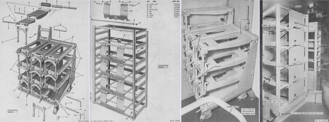
The 8" projectile and powder case racks are isolated in the left two images, respectively, and seen installed in the two right images. Note the different doors shown on the powder case racks. The key for the left image is: A. Cover, assy. 1. Clip. 2. Pin. 3. Cover. 4. Cover. B. Spring. C. Insert. D. Sleeve. E. Clip. F. Shaft. G. Cover. H. Shaft. J. Cover. K. Shaft. L. Clip. M. Shaft. N. Washer. P. Nut. Q. Handle. R. Bolt. S. Bolt. T. Latch. U. Latch. V. Shaft. W. Bolt. (Pictures from ORD 9 SNL G-259 List of All Service Parts of Gun, Self-propelled, Full Tracked: 155-mm, T97 and Howitzer, Self-propelled, Full Tracked: 8-in, T108 and TM 9-2350-210-12 Operation and Organizational Maintenance 155-mm Self-propelled Gun Cannon M52 (T97) and 8-inch Self-propelled Howitzer Cannon M55 (T108).)
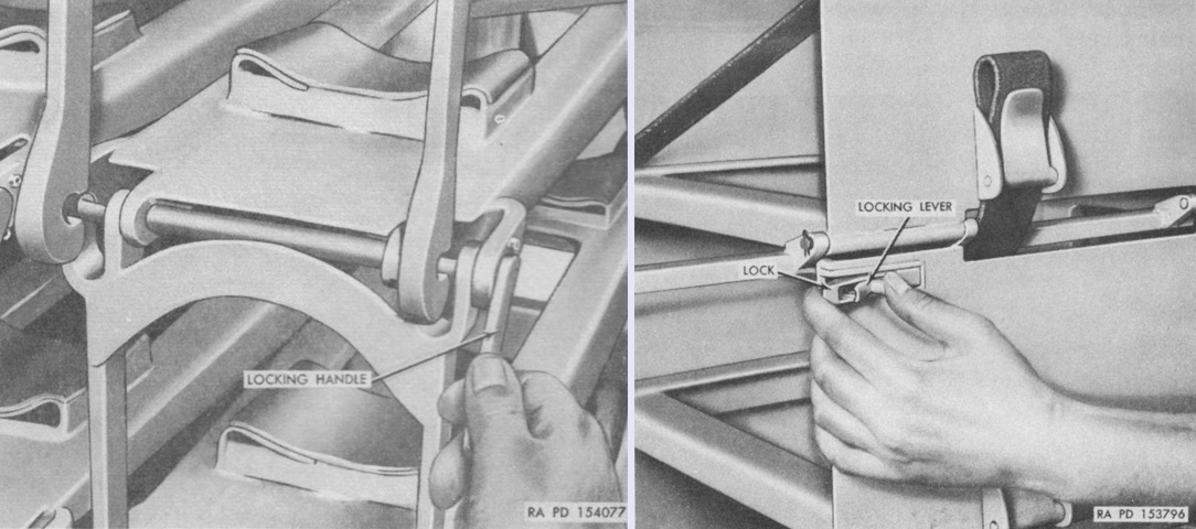
The controls for the 8" projectile and powder case racks are illustrated on the left and right, respectively. Projectiles were secured with lifting locking handles, while the cover of each tier of the powder case rack was locked with two squeezable levers. Canvas straps further secured the powder cases inside the rack. (Pictures from ORD 9 SNL G-259 List of All Service Parts of Gun, Self-propelled, Full Tracked: 155-mm, T97 and Howitzer, Self-propelled, Full Tracked: 8-in, T108.)
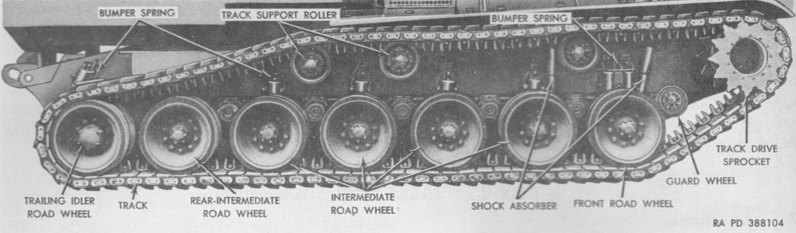
Suspension nomenclature is detailed in this image. The one-piece cast steel guard wheels in front of each forward road wheel prevented the hull from scraping on obstacles that might otherwise force the tracks behind the plane of the lower front hull. The steel-grouser, rubber-backed T80E6 was considered the combat track, while the rubber T84E1 was for training. (Picture from TM 9-2350-210-12 Operation and Organizational Maintenance 155-mm Self-propelled Gun Cannon M52 (T97) and 8-inch Self-propelled Howitzer Cannon M55 (T108).)
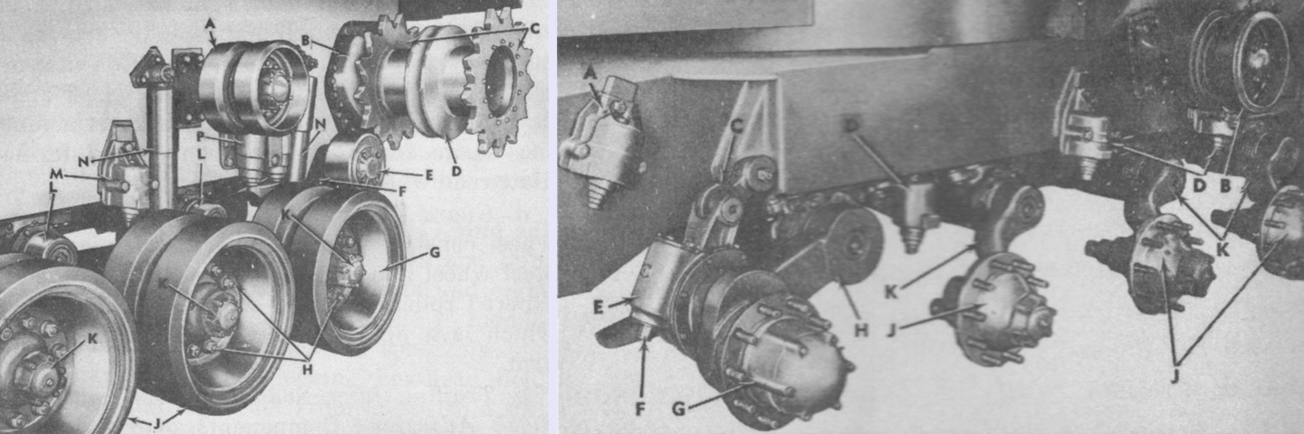
The front right-side suspension is seen in the left image with the track removed, and the rear right-side suspension is detailed on the right with both the track and road wheels dismounted. The legend for the left image is: A. Track support roller. B. Final drive. C. Track drive sprocket. D. Hub. E. Guard wheel. F. Front road wheel arm. G. Front road wheel. H. ⅞ in. (2.22cm) self-locking hex nut. J. Intermediate road wheel. K. Hub cap. L. Intermediate road wheel arm. M. Bumper spring. N. Shock absorber. P. Front bumper spring.
The legend for the right image is: A. Trailing idler bumper spring. B. Track support roller. C. Trailing idler link. D. Bumper spring. E. Slack adjuster. F. Slack adjuster pinion. G. Trailing idler road wheel hub. H. Trailing idler road wheel arm. J. Road wheel hub. K. Intermediate road wheel arm. (Pictures from TM 9-2350-210-12 Operation and Organizational Maintenance 155-mm Self-propelled Gun Cannon M52 (T97) and 8-inch Self-propelled Howitzer Cannon M55 (T108).)
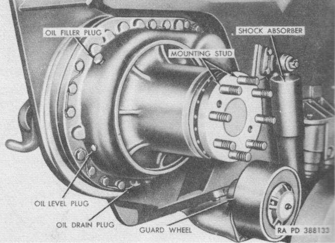
A final drive is shown with the drive sprockets and hub removed. (Picture from TM 9-2350-210-12 Operation and Organizational Maintenance 155-mm Self-propelled Gun Cannon M52 (T97) and 8-inch Self-propelled Howitzer Cannon M55 (T108).)
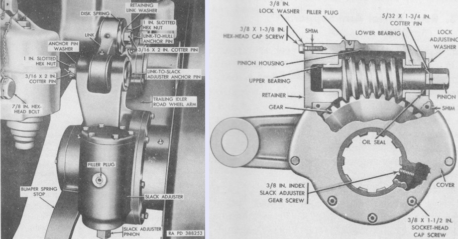
The trailing idler used the same wheel discs as the road wheels. The idler wheel hub was carried on an eccentric shaft supported on a yoked road wheel arm. The other end of the eccentric shaft carried the slack adjuster, which was a housed pinion and gear splined to the eccentric shaft. Track tension was adjusted by turning the pinion, thereby rotating the idler wheel assembly on the eccentric shaft. The pinion was turned clockwise to loosen the track and counterclockwise to tighten the track, and total possible adjustment was 3" (7.6cm). (Picture from TM 9-2350-210-12 Operation and Organizational Maintenance 155-mm Self-propelled Gun Cannon M52 (T97) and 8-inch Self-propelled Howitzer Cannon M55 (T108).)
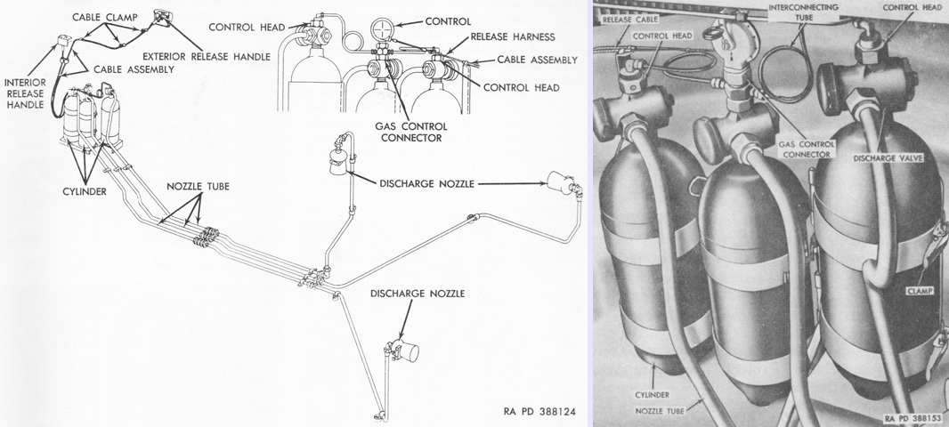
The fixed fire extinguisher system consisted of three 10lb (4.5kg) CO2 cylinders mounted in the left side of the turret support compartment and routed to extinguish fires in the engine compartment. They were discharged simultaneously by pulling the interior or exterior release handles. A schematic of the fixed fire extinguisher system is drawn on the left, and the three CO2 cylinders are seen on the right. A 5lb (2.3kg) portable CO2 extinguisher was also carried. (Picture from TM 9-2350-210-12 Operation and Organizational Maintenance 155-mm Self-propelled Gun Cannon M52 (T97) and 8-inch Self-propelled Howitzer Cannon M55 (T108).)
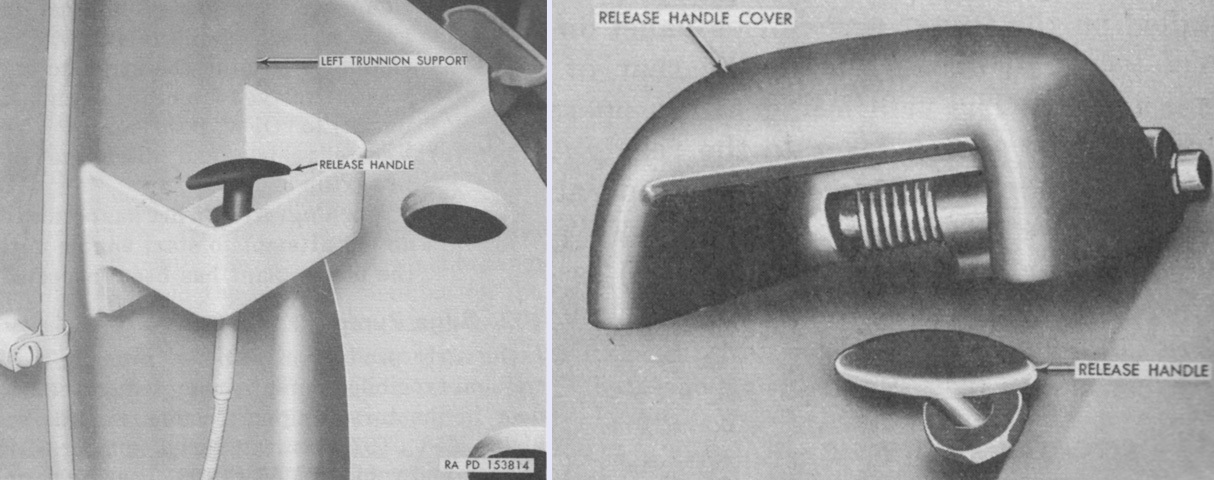
The bracket for the fixed fire extinguisher internal release handle was welded to the side of the howitzer's left trunnion support, as seen on the left, while the outer release handle was under a hinged cover on the left turret exterior wall. (Picture from TM 9-2350-210-12 Operation and Organizational Maintenance 155-mm Self-propelled Gun Cannon M52 (T97) and 8-inch Self-propelled Howitzer Cannon M55 (T108).)
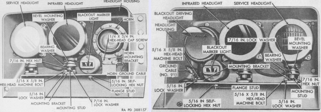
The right-side headlight housing is above at the left, with the left-side headlight housing on the right. The housings were bolted to the vehicle hull and the right and left air ducts.The infrared headlights were identical to the service headlights except for the lens color. (Picture from TM 9-2350-210-12 Operation and Organizational Maintenance 155-mm Self-propelled Gun Cannon M52 (T97) and 8-inch Self-propelled Howitzer Cannon M55 (T108).)
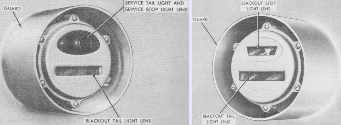
The left and right tail lights are on the left and right, respectively. The tail lights were mounted to the turret rear. (Picture from TM 9-2350-210-12 Operation and Organizational Maintenance 155-mm Self-propelled Gun Cannon M52 (T97) and 8-inch Self-propelled Howitzer Cannon M55 (T108).)
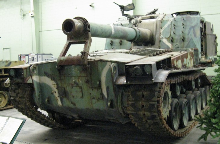
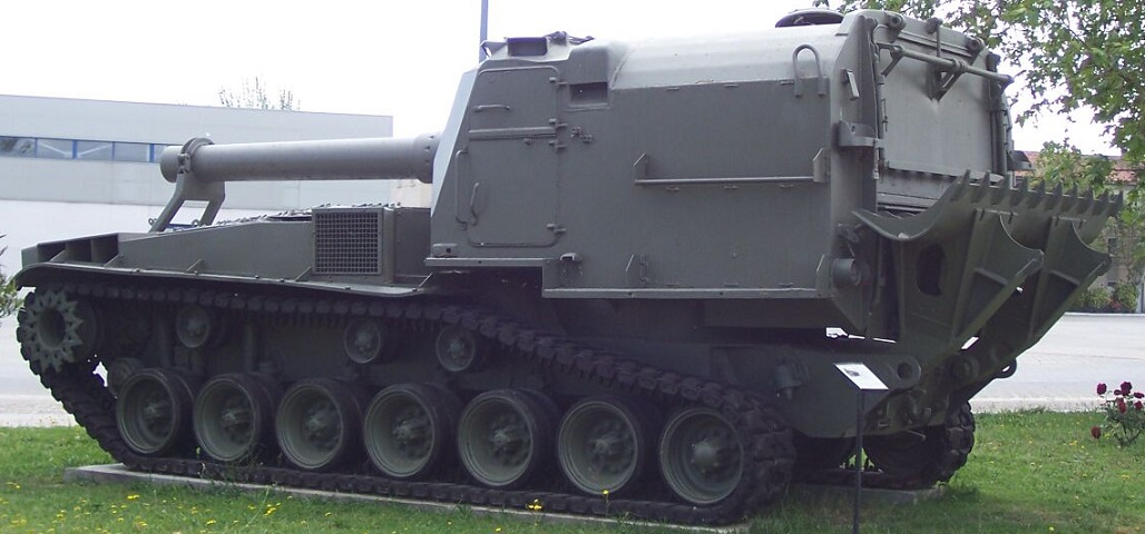
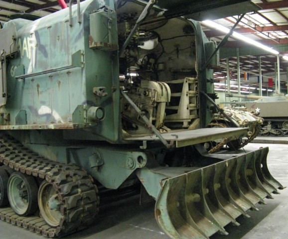
The running gear of the M55 and the 155mm self-propelled gun M53 was based on that of the M46 and M47 tanks. The howitzer is stowed in its travel lock, and a machine gun is mounted at the commander's cupola on the turret roof. Air intake louvers are visible on the front slope just inboard of the fender-mounted stowage boxes.
The gunner's doors are open on the turret's right side, and stowage mounts for spare track blocks are attached to the front of the turret. The support for the telescope M99 is attached to the ordnance mantlet. A small guard wheel can just be seen between the front drive sprocket and the first road wheel.
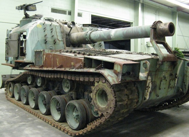
The gunner's doors are closed on this vehicle, allowing us a better look at the large lower and small upper pieces. Two air exhaust ducts are present on each side: one above the drive sprocket and one covered by a mesh screen in front of the turret. The muffler for the auxiliary engine can just be made out behind the mesh screen. The recoil spade is in its stowed position. (Picture courtesy Jose Maria Serrano.)
The driver also had a pair of horizontally-split doors on the opposite side of the turret, and his periscopes can be seen on the roof above his doors. Directly behind the driver's doors is the outlet for the turret ventilating blower. (Picture courtesy Jose Maria Serrano.)
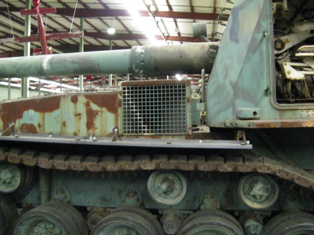
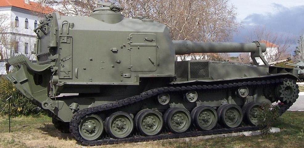
The rear air exhaust duct is highlighted here. More details of the suspension can be viewed in this image as well.
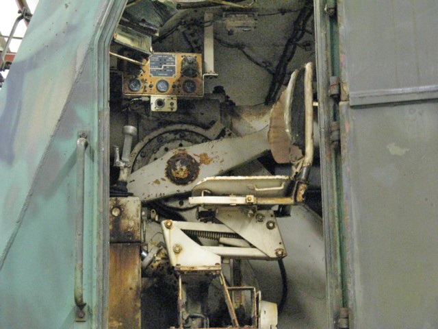
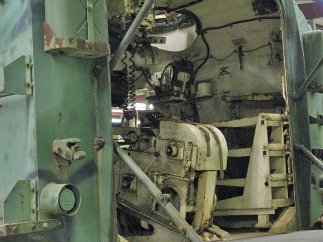
This view is peering into the open driver's door on the turret's left side. The driver's seat and wobble stick control common to the M46 and M47 tanks can be seen in the foreground. The main instrument panel is attached to the turret roof. The howitzer mount and its recoil and equilibrator cylinders can be seen behind the driver's seat.
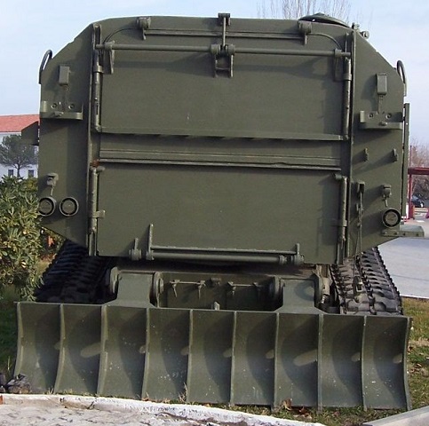
The spade is lowered on this machine, giving us a view of the two turret rear doors, which are hinged on the top and bottom of the turret rear to provide a platform and roof when opened. Between the legs of the spade are two rear stowage compartment access doors. (Picture courtesy Jose Maria Serrano.)
The turret rear doors are open on this vehicle. The stabilization spade is lowered, and the left taillight can be seen just above the fender. The final bumper spring is visible above the trailing idler wheel. Inside the turret, a projectile stowage rack is in the rear corner, and the projectile rammer and spade hoist is centered in the turret opening.
A closer view of the rear turret interior is offered here. The commander's seat can be seen under his cupola.
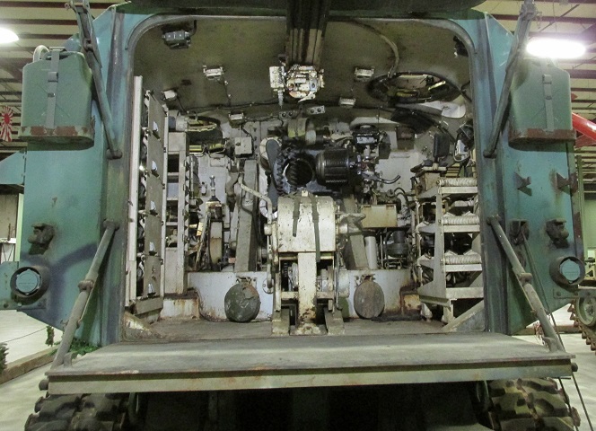
This angle provides a more expansive shot of the interior. The breech of the howitzer is open, and the commander's and driver's cupolas can be seen in the turret roof. The position of the projectile rammer is right below the breech opening.
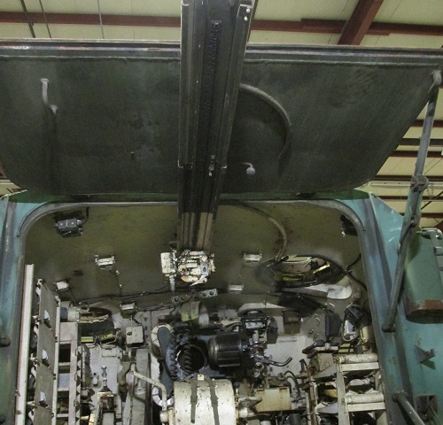
The hoist rear track is connected to the front track. The arcs used to swing the hoist tracks can also be seen on the turret rear door and turret roof.
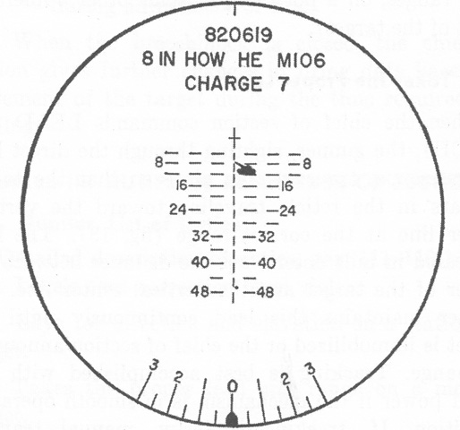
The reticle for the direct-fire telescope T159E1 is sketched. The cross represented zero range and deflection and was used during boresighting. The vertical range line was numbered in hundreds of yards, and each line and space of the broken horizontal lines represented a deflection of 5 mils. The gunner above is depicted engaging a tank at 1,200 yards (1,100m) with a 5 mil lead. (Picture from FM 6-93 155-mm Gun M53, Self-propelled and 8-inch Howitzer M55, Self-propelled.)
