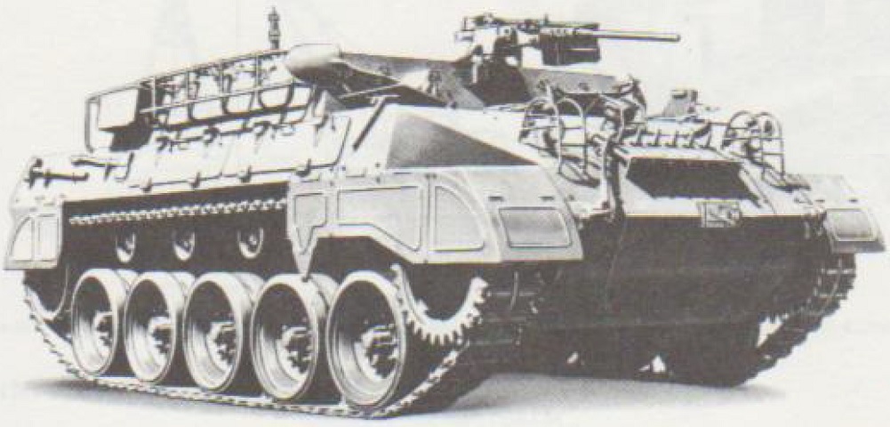
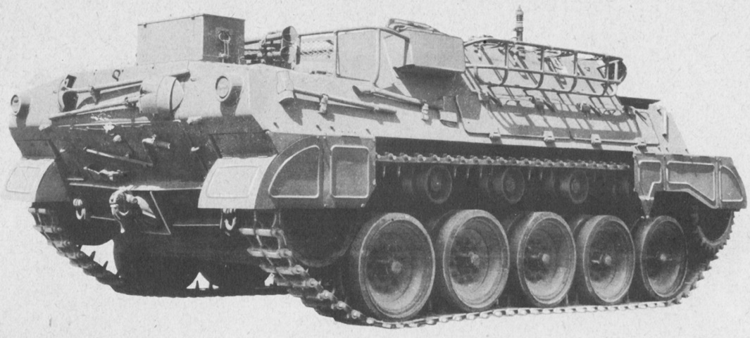
Armored Utility Vehicle M39.
The M39's basis on the 76mm GMC M18 is apparent when the running gear is compared. The turrets have been omitted in favor of an open-topped cargo and troop compartment. (Picture from TM 9-2800-1/TO 19-75A-89.)
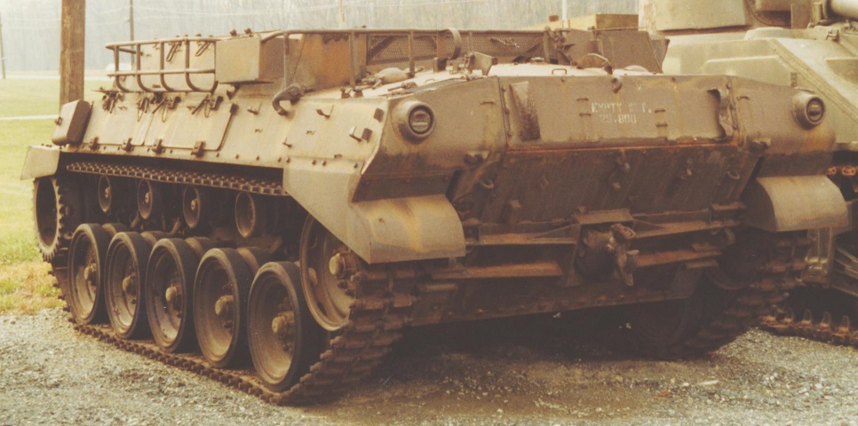
The arrangement of the front of the vehicle is illustrated here. The drivers were positioned under the low roof in front of the superstructure. The headlights are missing from this vehicle, though their guards remain, but the siren is present in the center of the front hull.
Stowage baskets were added to the superstructure sides and rear, and stowage compartments are visible along the hull sides above the tracks. (Photo by Richard S. Eshleman.)
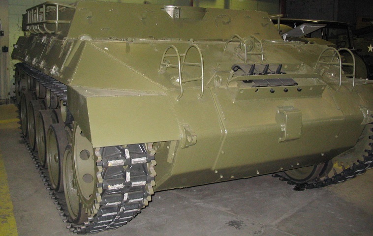
The engine access arrangement and towing pintle were carried over from the 76mm GMC M18. (Photo by Richard S. Eshleman.)
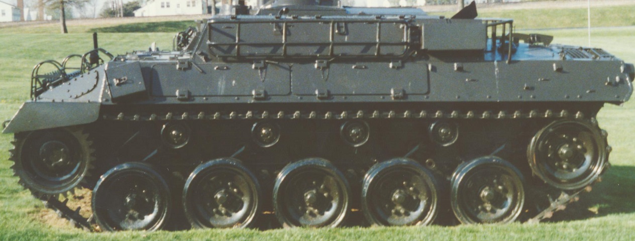
The opposite side of the vehicle is seen here. (Picture from TM 9-755 76-mm Gun Motor Carriage M18 and Armored Utility Vehicle M39.)
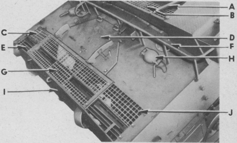
The rear deck of the vehicle is shown here. A. Water can retainer. B. Hull air inlet grille. C. Oil tank filler screen door. D. Hull rear roof door. E. Hull air outlet grille left. F. Fuel tank gage cover. G. Hull air outlet grille center. H. Fuel tank cap cover. I. Hull rear upper plate. J. Hull air outlet grille right. (Picture from TM 9-755 76-mm Gun Motor Carriage M18 and Armored Utility Vehicle M39.)
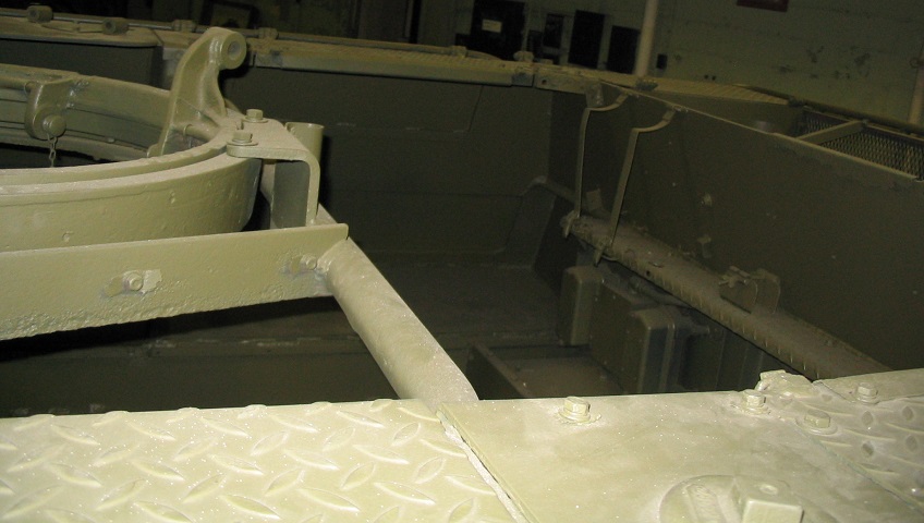
The rear of the troop compartment is shown in this image. The machine gun ring mount is to the left of the picture, and the interior space for crew and stowage is obvious.
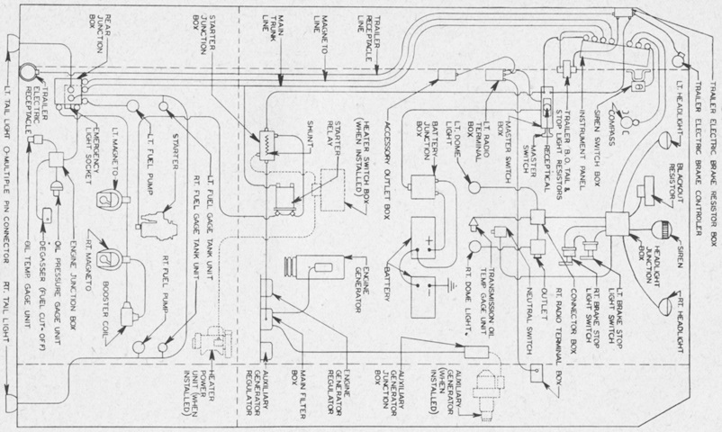
This schematic of electrical components reveals the new location of the batteries versus the M18, which on the M39 were moved to the front portion of the cargo compartment under one of the two transverse seats. (Picture from TM 9-755 76-mm Gun Motor Carriage M18 and Armored Utility Vehicle M39.)
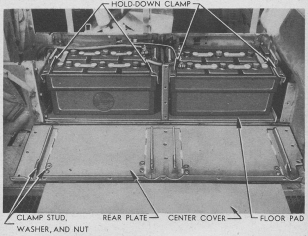
The battery box has been disassembled, revealing the two 12-volt, 168 ampere hour, 6-cell storage batteries connected to provide single-wire with ground-return circuits of both 12 and 24 volts. The 12-volt circuit was used by the radio, while all other electrical units used 24-volt current. (Picture from TM 9-755 76-mm Gun Motor Carriage M18 and Armored Utility Vehicle M39.)
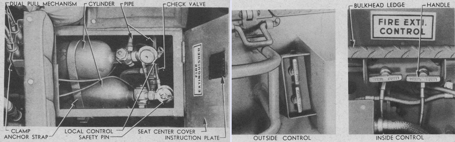
The fixed fire extinguisher system consisted of two 10lb (4.5kg) CO2 cylinders routed to six discharge horns in the engine compartment. The cylinders were located under the rear seat center cover and could be actuated by two sets of remote control handles, one on the left sponson between the stowage rack and windshield stowage box, and the other under the bulkhead ledge at the rear of the crew compartment. Each handle in each location discharged a single cylinder, and the cylinders could also be actuated by raising the seat cover over the cylinders and moving the lever on the local control. In addition, a portable fire extinguisher was stowed in the sponson beside the assistant driver. (Picture from TM 9-755 76-mm Gun Motor Carriage M18 and Armored Utility Vehicle M39.)
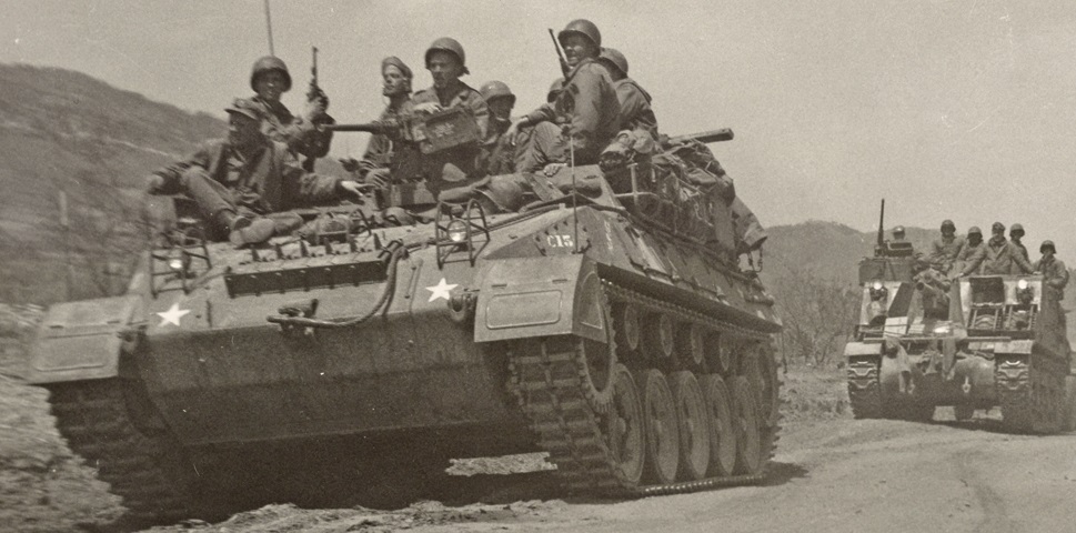
A loaded M39 is leading a 105mm HMC M7B1 to the rear on the central Korean front as Army units were relieved by the First Marine Division. (Picture by Sgt Peter W. McDonald; available from the National Archives.)
