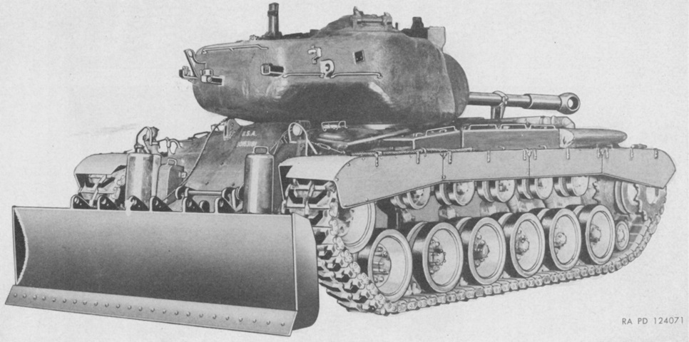
Tank-Mounting Bulldozer M3.
The tank-mounting bulldozer M3 was designed for installation on the medium tank M46 Patton. Including the required hydraulic oil, the kit increased the weight of the vehicle by 6,000lb (2,700kg). The tank was able to achieve 1-2mph (1.6-3.2kph) while bulldozing with the engine at 1,500rpm and the transmission in low gear. Recommended top speed with the bulldozer attached was 15mph (24kph). (Picture from TM 9-723 Tank-Mounting Bulldozer M3.)
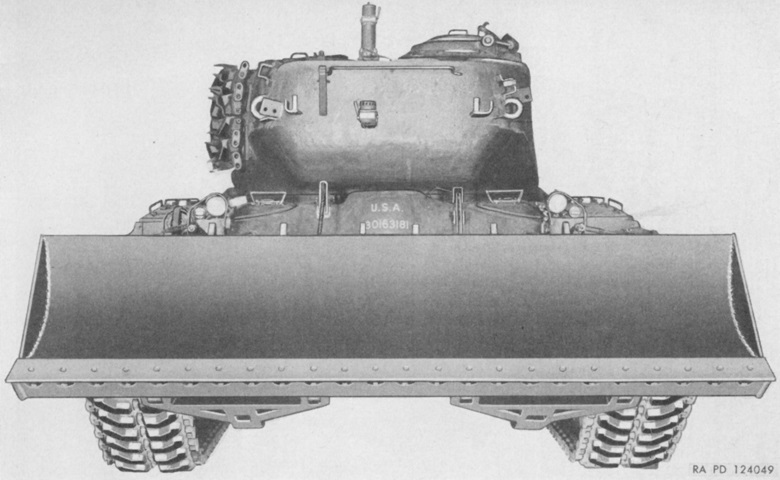
The carrying position held the moldboard's cutting edge 29" (74cm) above the ground; the cutting edge was 30 ¼" (76.84cm) above the ground in its highest position and 9" (23cm) below ground level in its lowest position. The tank's angle of approach was 21° with the moldboard in its carrying position and 25° with it in the highest position. (Picture from TM 9-723 Tank-Mounting Bulldozer M3.)
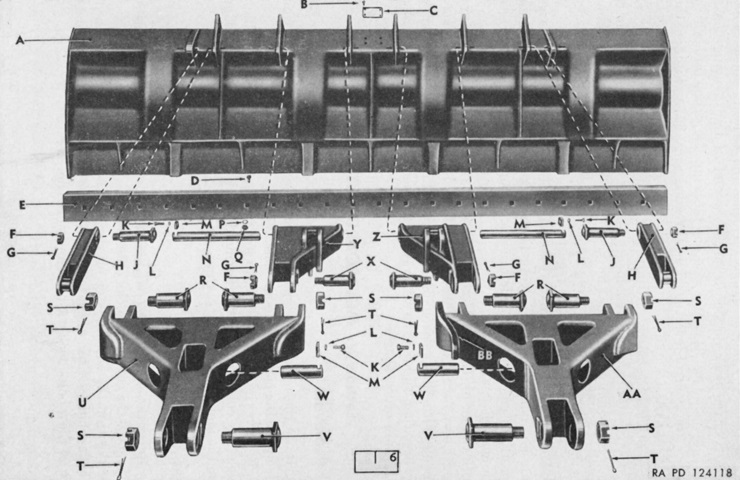
The moldboard and its attachments are shown here from the rear. The moldboard was 146" (371cm) wide by 36 ¾" (93.35cm) high, and its reversible cutting edge was 146" (371cm) x 8" (20cm) x ¾" (1.9cm). The cutting edge's angle with horizontal was 58° in the float position and 60° in the lowest position. A. Moldboard. B. ½-10-24NC-2 screw. C. Name plate. D. ¾-10NC-2 x 2 ¾ plow bolt. E. Moldboard cutting edge. F. 1 ½-12NF-3 nut. G. ⅜ x 2 ½ cotter pin. H. Outer tilt arm. J. Moldboard-to-outer-tilt-arm pin. K. ⅝-18-3 x 1 ¾ screw. L. ⅝" lock washer. M. Pin lock. N. Moldboard-to-inner-tilt-arm pin. P. ¾" lock washer. Q. ¾-10NC-2 nut. R. Moldboard-to-push-beam pin. S. 1 ¾-10NF-3 nut. T. ⅜ x 3 ½ cotter pin. U. Left push beam. V. Push-beam-to-push-beam-bracket pin. W. Push-beam-to-hydraulic-cylinder-ram pivot pin. X. Inner-tilt-arm-to-inner-tilt-arm-bracket pin. Y. Left-inner tilt arm. Z. Right-inner tilt arm. AA. Right push beam. BB. Cable-connector boss. (Picture from TM 9-723 Tank-Mounting Bulldozer M3.)
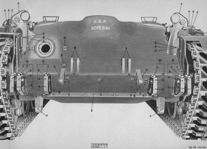
The bulldozer mounting brackets and hydraulic-line guard mounting blocks are shown welded to the hull front. Before installation, it was necessary to remove the tank's tools and tool rack, and to cut off the tool rack's six mounting blocks; remove the headlights, brackets, and guards; cut off the tow locks and brackets on the front hull; cut off the sledge holder, handle bracket, and strap fastener; cut off the tow cable lock from the hull front; remove the front fenders; and remove the bow machine gun and its exterior guard. The tool rack, sledge holder, and cable lock were reinstalled in new locations, and the front fenders were reinstalled after modifications were implemented. The bow machine gun and front tow hooks were not used with the bulldozer mounted. Note the headlights reinstalled in new brackets attached to the front fenders. (Picture from ORD 9 SNL G-246 List of All Service Parts of Bulldozer, Tank-Mounting, M3.)
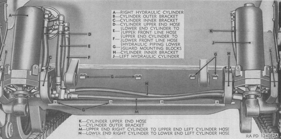
Two double-acting hydraulic cylinders raised and lowered the moldboard. (Picture from TM 9-723 Tank-Mounting Bulldozer M3.)
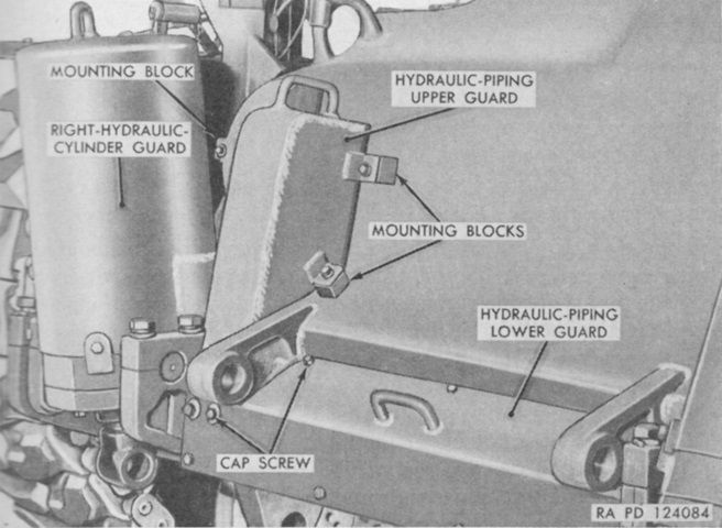
Protective guards were installed over the cylinders and the hydraulic piping. (Picture from TM 9-723 Tank-Mounting Bulldozer M3.)
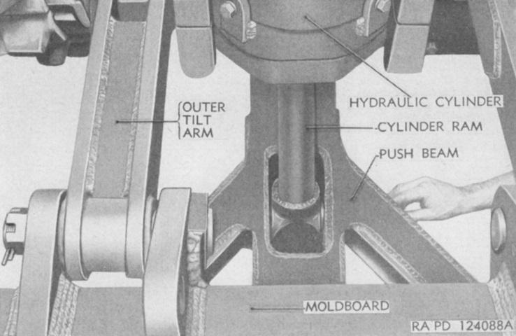
The connection of the left-side hydraulic cylinder ram to the left push beam can be seen here. (Picture from TM 9-723 Tank-Mounting Bulldozer M3.)
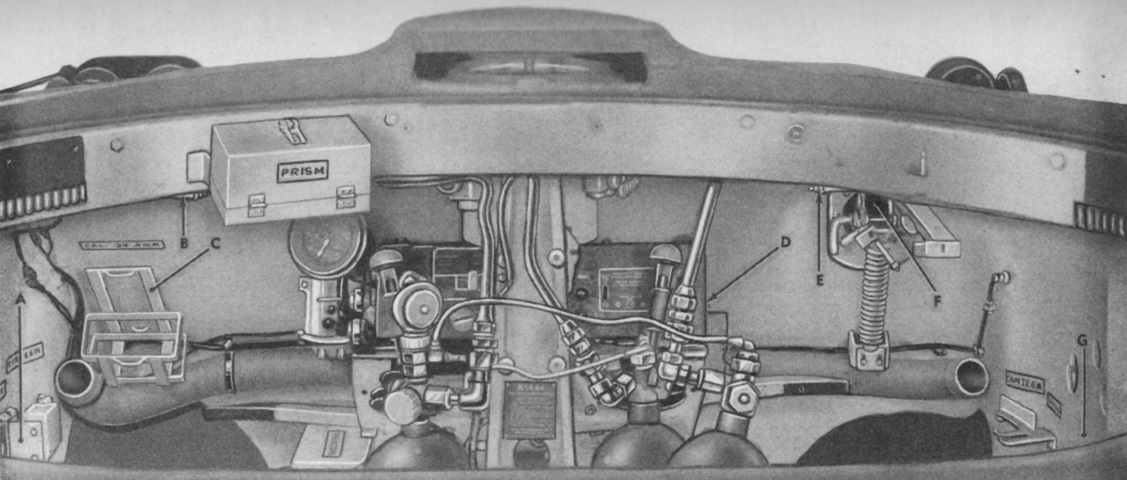
Modifications were also required in the hull interior. It was possible and recommended for these modifications to be performed with the turret installed, but removing the turret would make the job easier and faster. In this view, looking forward into the driver's compartment through the turret opening, both drivers' hand grips were cut off and not reinstalled. Similarly, both machine gun ammunition racks were cut off, and the blackout driving light bracket was cut off of the left-side wall and reinstalled in a new location. A. Blackout driving light bracket. B. Driver's hand grip. C. Cal. .30 ammunition rack. D. Cal. .30 ammunition rack. E. Assistant driver's hand grip. F. Cal. .30 machine gun. G. New location for blackout driving light bracket. (Picture from TM 9-723 Tank-Mounting Bulldozer M3.)
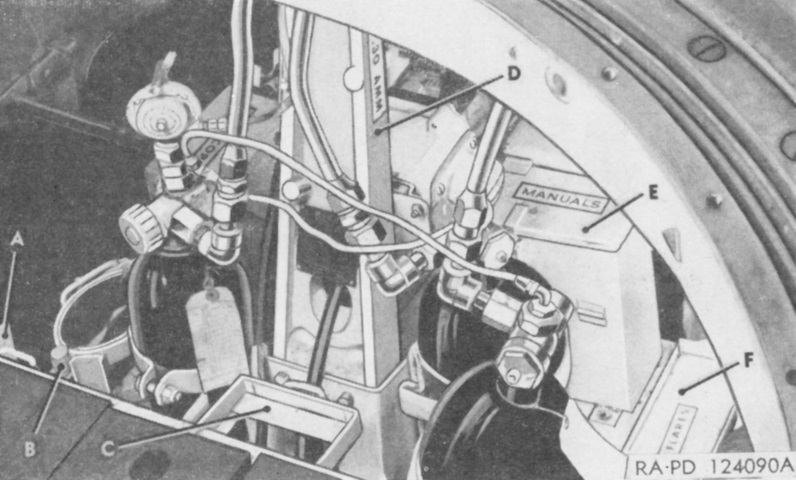
At the rear of the drivers' compartment, more machine gun ammunition brackets were cut away and not reused. The battery and spare-bulb bracket and the flashlight bracket were cut off and reinstalled in new locations. The manuals box and signal-flare tray were also removed and relocated. A. Cal. .30 ammunition rack. B. Flashlight bracket. C. Battery and spare bulb bracket. D. New location for flash light [sic] bracket. E. Manuals box. F. Signal flare tray. (Picture from TM 9-723 Tank-Mounting Bulldozer M3.)
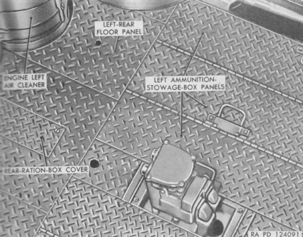
In the fighting compartment, the .30 caliber ammunition box was removed from under the left rear floor plate, and all 90mm ammunition and racks were removed from the left side except the rack against the left side of the hull. The rear ration box was also removed. None of these were reused. (Picture from TM 9-723 Tank-Mounting Bulldozer M3.)
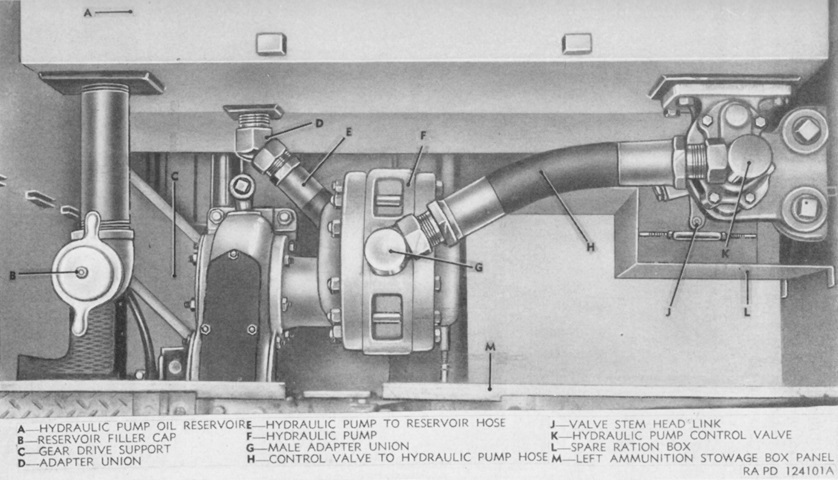
In the space formerly occupied by ammunition racks under the turret floor was installed an oil reservoir and an hydraulic pump that was driven off of the accessory power take-off shaft of the main engine. A 3 ½" (8.9cm) hole was cut or torched into the engine compartment bulkhead, and a propeller shaft connecting the pump to the engine's accessory power take-off shaft was installed in the space formerly occupied by the ration box. (Picture from TM 9-723 Tank-Mounting Bulldozer M3.)
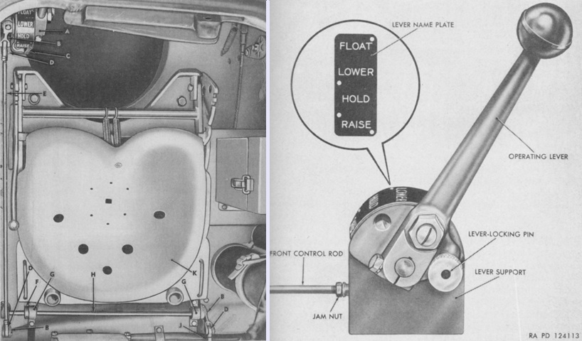
The control-valve operating lever was welded to the left wall of the driver's position, as shown from above on the left. A closer view of the lever is provided in the right image. There were four positions for the control lever: from front to rear, these were Float, Lower, Hold, and Raise. Lower and Raise executed their respective actions on the moldboard. Hold caused the moldboard to be locked at its current height. Float allowed the moldboard to be moved by external forces.
The legend for the left image is: A. Control valve operating lever. B. Control valve control yoke. C. Lever mounting bracket. D. Control rod end eye. E. Front control rod. F. Collar. G. Shaft support. H. Control valve control shaft. J. Rear control rod. K. Driver's seat. (Picture from TM 9-723 Tank-Mounting Bulldozer M3.)
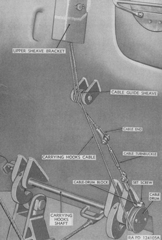
The moldboard carrying hooks and cable are shown here from above; the driver's hatch door is at the upper right and the hull ventilator is at the upper left. A 2 ¾" (6.99cm) hole was cut into the hull roof straight up from the cable drum 10" (25cm) from the rim of the turret well, and the cable was fed into the drivers' compartment through this hole. (Picture from TM 9-723 Tank-Mounting Bulldozer M3.)
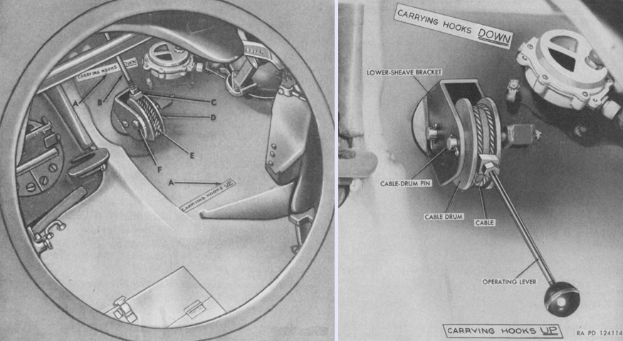
On the left, a view through the open hull floor escape hatch shows the carrying hooks operating lever and cable drum installed on the hull roof. The lever is highlighted on the right. The lever rotated the carrying hooks via the attaching cable, and thereby engaged or disengaged them from the moldboard. The legend for the left image is: A. Decalomania. B. Carrying hooks operating lever. C. Cable drum block. D. Cable drum. E. Carrying hooks cable. F. Cable lower sheave bracket. (Picture from TM 9-723 Tank-Mounting Bulldozer M3.)
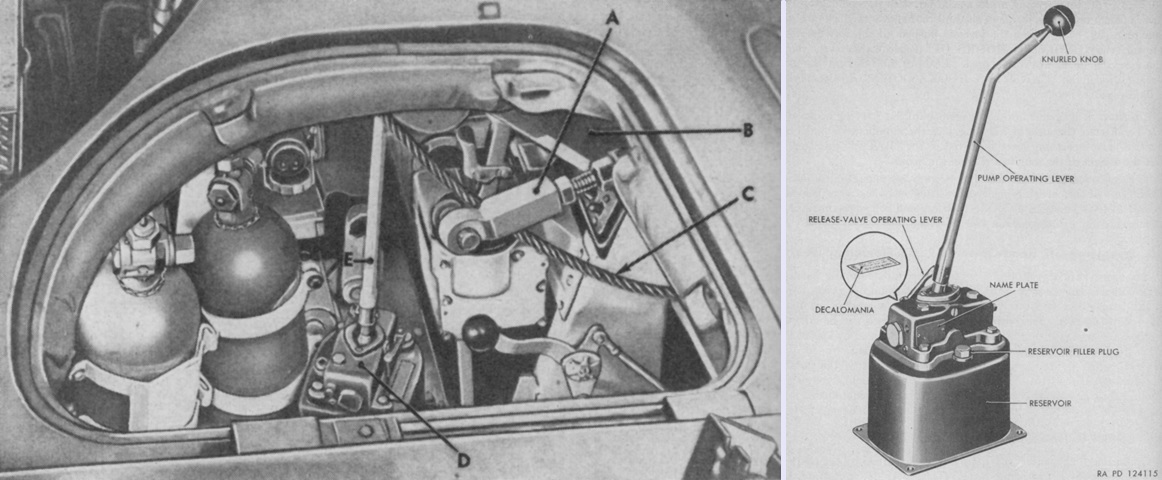
An emergency-lift hydraulic jack was provided to raise the moldboard in the event of hydraulic power loss. Its installation to the left of the assistant driver is shown on the left, and the pump is detailed on the right. Back and forth action of the lever actuated the jack and raised a cable attached to the right push beam, which entered the tank interior via a 3 ⅞" (9.843cm) to 4 ¼" (10.8cm) diameter hole cut into the hull roof just to the right of the ventilator housing. The legend for the left image is: A. Cable clevis. B. Hydraulic jack. C. Emergency lift cable. D. Hand operated pump. E. Pump operating lever. (Picture from TM 9-723 Tank-Mounting Bulldozer M3.)
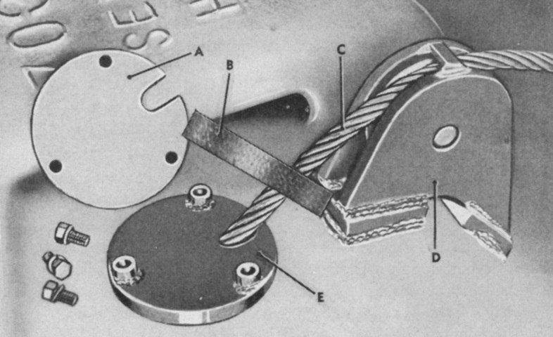
The cable for the emergency lift jack is shown where it enters the hull roof. A. Weather seal retainer. B. Cable guide weather seal. C. Emergency lift cable. D. Cable outer sheave support. E. Cable guide. (Picture from TM 9-723 Tank-Mounting Bulldozer M3.)
