Tank Mounting Bulldozer M4.
The tank mounting bulldozer M4 was the second bulldozer design applied to the light tank M24 Chaffee. The first, the tank mounting bulldozer T4, was developed from the tank mounting bulldozer M1 as installed on the medium tank M4 Sherman. The bulldozers were intended for road grading or similar earth moving tasks. Including the required hydraulic oil, the M4 increased the tank's weight by 3,580lb (1,620kg). The forward speed of the tank while bulldozing with its right engine at 3,400rpm and in low gear was 3mph (5kph), and the recommended maximum speed with the moldboard in the carry position was 15mph (24kph). (Picture from TM 9-7408 Operation, Organizational Maintenance, and Ordnance Field and Depot Maintenance Earth Moving Tank Mounting Bulldozer M4.).
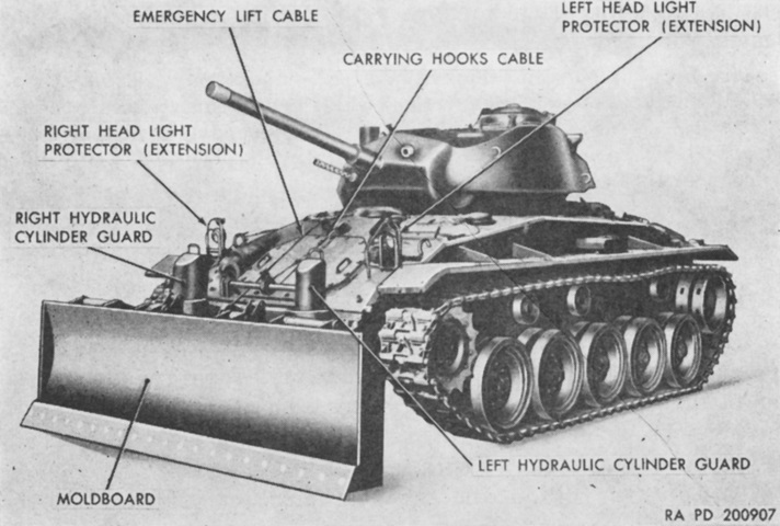
Like the tank mounting bulldozer M1 whence it was derived, the T4 required attachments to the hull side. This was rectified on the M4, as visible from this angle. All supports and related equipment were installed on the hull front. The carry position of the moldboard was 26.5" (67.3cm) above ground level, and the lowest position was 6.5" (17cm) below ground level. The tank's angle of approach with the moldboard in the carry position was 21.5°, and with the moldboard in its highest position was 26.5°. (Picture from TM 9-7408 Operation, Organizational Maintenance, and Ordnance Field and Depot Maintenance Earth Moving Tank Mounting Bulldozer M4.)
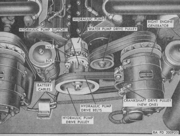
An hydraulic pump was installed in the engine compartment, and was powered by the right engine. A new 5-groove crankshaft drive pulley replaced that engine's original 3-groove pulley. To make room, the rear terminal block was moved ~10" (~25cm) to the rear, and ⅜" (.953cm) was shaved from the bottom of the projecting boss of the right engine's generator cradle. (Picture from TM 9-7408 Operation, Organizational Maintenance, and Ordnance Field and Depot Maintenance Earth Moving Tank Mounting Bulldozer M4.)
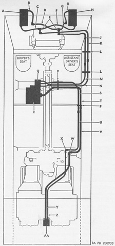
Hydraulic tubes and hoses are diagrammed in this schematic. A. Left hydraulic cylinder. B. Hydraulic cylinder upper hose assembly. C. Left hydraulic cylinder lower hose assembly. D. Left hydraulic cylinder upper tube. E. Hydraulic cylinder upper and lower tee nipple (welded to hull). F. Right hydraulic cylinder lower hose assembly. G. Right hydraulic cylinder upper tube. H. Right hydraulic cylinder. J. Hydraulic cylinder upper nipple to control valve forward right tube. K. Hydraulic cylinder lower nipple to control valve forward left tube. L. Hydraulic cylinder to control valve tubes clips. M. Hydraulic cylinder upper nipple to control valve rear right tube. N. Hydraulic cylinder lower nipple to control valve rear left tube. P. Hydraulic oil tank to hydraulic pump hose, and control valve to hydraulic cylinder hose clamp. Q. Control valve. R. Hydraulic oil tank. S. Hydraulic pump hose to control valve forward tube. T. Hydraulic oil tank to hydraulic pump hose forward tube. U. Hydraulic pump hose to control valve rear tube. V. Hydraulic oil tank to hydraulic pump hose rear tube. W. Hydraulic pump right hose elbow (welded to plate 7051036). X. Hydraulic pump left hose elbow (welded to plate 7051036). Y. Hydraulic pump left hose assembly. Z. Hydraulic pump right hose assembly. AA. Hydraulic pump. (Picture from TM 9-7408 Operation, Organizational Maintenance, and Ordnance Field and Depot Maintenance Earth Moving Tank Mounting Bulldozer M4.)
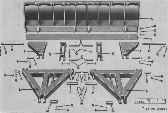
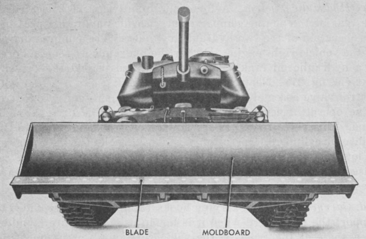
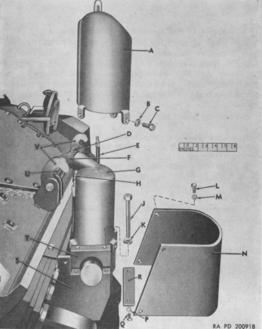
The moldboard was 124" (315cm) wide and 35" (89cm) high with a 3.25" x 8" x 124" (8.26cm x 20cm x 315cm) reversible blade. The blade's angle with vertical was 62° in the highest position and 21.5° in the lowest position. The moldboard is shown here from the rear with its attachments labeled. A. Moldboard. B. Bolt. C. Washer. D. Nut. E Blade. F. Locking pin. G. Cotter pin. H. Moldboard to outer tilt arm pin. J. Outer tilt arm. K. Outer tilt arm to outer tilt arm bracket, inner tilt arm to inner tilt arm bracket, and moldboard to push beam pin. L. Push beam. M. Push beam to push beam bracket pin. N. Locking pin. P. Push beam to hydraulic cylinder pivot pin. Q. Inner tilt arm. R. Moldboard to inner tilt arm pin. (Picture from TM 9-7408 Operation, Organizational Maintenance, and Ordnance Field and Depot Maintenance Earth Moving Tank Mounting Bulldozer M4.)
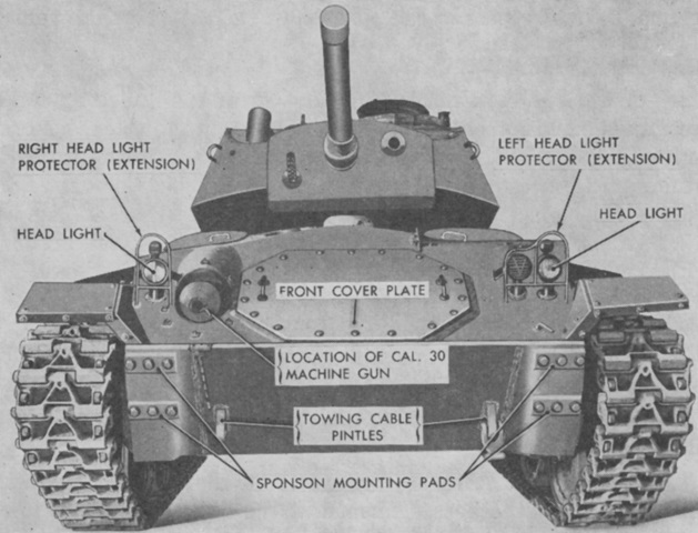
When the bulldozer was installed, the front steps and the bow machine gun were removed, as were the towing cable pintles. The tow cable could be used from the rear of a bulldozer tank, but not the front. Extensions for the headlights and taller brush guards were provided with the installation kit. (Picture from TM 9-7408 Operation, Organizational Maintenance, and Ordnance Field and Depot Maintenance Earth Moving Tank Mounting Bulldozer M4.)
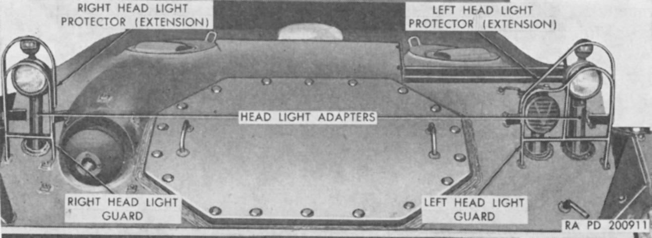
The headlights are shown here installed on their extensions, and the new brush guards have been welded into place. (Picture from TM 9-7408 Operation, Organizational Maintenance, and Ordnance Field and Depot Maintenance Earth Moving Tank Mounting Bulldozer M4.)
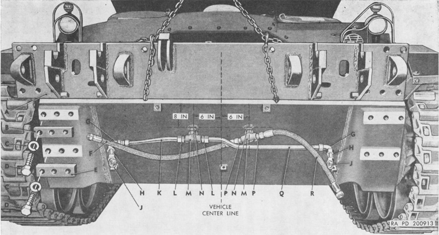
In order to route the hydraulic lines from the hull interior to the external cylinders, a cutting torch was used to burn two holes through the lower front hull. The positioning of the holes (6" [15cm] either side of the hull center line and 8" [20cm] down from the edge of the hull front plate) is illustrated here; they were to be just large enough to accept a 1" (2.5cm) outside diameter nipple. The trunnion support plate, being lowered into position by a chain in this picture, could then be mounted onto its mounting pads and have the hose assemblies threaded through the provided holes. A. Trunnion support plate. B. Trunnion support plate upper mounting pad (thin). C. Lockwasher. D. Bolt. E. Trunnion support plate lower mounting pad (thick). F. Right hydraulic cylinder lower hose assembly. G. Hydraulic cylinder upper tube elbow. H. Hydraulic cylinder piping nipple. J. Hydraulic cylinder upper hose elbow. K. Right hydraulic cylinder upper tube. L. Hydraulic cylinder upper tube connector. M. Hydraulic cylinder tube reducer tee. N. Hydraulic cylinder tube reducer tee nipple. P. Hydraulic cylinder lower hose adapter. Q. Left hydraulic cylinder upper tube. R. Left hydraulic cylinder lower hose assembly. (Picture from TM 9-7408 Operation, Organizational Maintenance, and Ordnance Field and Depot Maintenance Earth Moving Tank Mounting Bulldozer M4.)
Components of one of the hydraulic cylinders and its guards are diagrammed here. A. Right hydraulic cylinder guard. B. Lockwasher. C. Bolt. D. Carrying hook cable drum block. E. Hydraulic cylinder upper hose assembly. F. Carrying hook cable shaft drum. G. Right hydraulic cylinder. H. Hydraulic cylinder upper hose adapter. J. Bolt. K. Lockwasher. L. Bolt. M. Lockwasher. N. Hydraulic cylinder lower guard. P. Lockwasher. Q. Bolt. R. Cylinder guard lower plate. S. Hydraulic cylinder bracket. T. Hydraulic cylinder bracket cap. U. Carrying hook shaft. V. Carrying hooks. (Picture from TM 9-7408 Operation, Organizational Maintenance, and Ordnance Field and Depot Maintenance Earth Moving Tank Mounting Bulldozer M4.)

Two openings were to be cut into the upper front hull of the tank for the carrying hook and emergency lift cables. The carrying hook cable opening was 2⅜" (6.033cm) wide by 3¾" (9.53cm) long. Its shorter center line was to be 34⅛" (86.678cm) from the top rear edge of the lower hull plate, and its longer center line was to be on the hull center line. The emergency lift cable opening was 2¾" (6.99cm) wide by 7½" (19cm) long, with its longer center line 7¾" (19.5cm) to the right of the vehicle center line and its front edge 2" (5cm) back from the top edge of the upper hull plate. A. Emergency lift mounting bracket. B. Carrying hook sheave and drum bracket. C. Carrying hook cable end. D. Carrying hook cable turnbuckle. E. Carrying hook cable. F. Carrying hook drum block. G. Carrying hook shaft drum. H. Carrying hook shaft. J. Carrying hook. K. Carrying hook engagement pin. L. Moldboard nameplate. M. Moldboard. N. Emergency lift cable. P. Emergency lift sheave bracket. Q. Emergency lift cable bracket. (Picture from TM 9-7408 Operation, Organizational Maintenance, and Ordnance Field and Depot Maintenance Earth Moving Tank Mounting Bulldozer M4.)
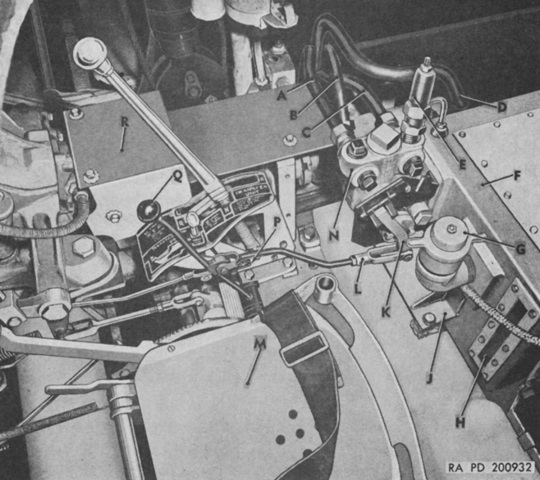
Controls and fixtures at the driver's position are illustrated here. There were four positions for the control lever: from front to rear, these were Float, Lower, Hold, and Raise. Lower and Raise executed their respective actions on the moldboard. Hold caused the moldboard to be locked at its current height. Float allowed the moldboard to be moved by external forces.
A. Hydraulic cylinder lower nipple to control valve rear left tube. B. Hydraulic pump hose to control valve forward tube. C. Hydraulic cylinder upper nipple to control valve rear right tube. D. Hydraulic oil tank to hydraulic pump hose forward tube assembly. E. Unloader valve assembly. F. Hydraulic oil tank. G. Filler cap assembly. H. Oil level gage. J. Bracket. K. Valve operating control. L. Valve operating control yoke. M. Driver's seat. N. Control valve. P. Control valve operating lever diagram plate. Q. Control valve operating lever. R. Front main propeller shaft cover guard. (Picture from TM 9-7408 Operation, Organizational Maintenance, and Ordnance Field and Depot Maintenance Earth Moving Tank Mounting Bulldozer M4.)
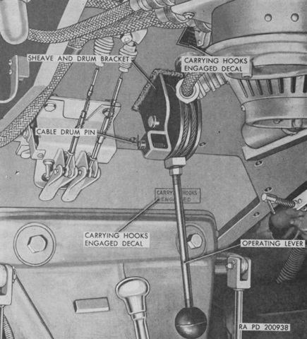
The carrying hook operating lever is shown installed. The moldboard was to be secured by the carrying hooks during travel. When necessary to release the hooks, the operating lever was pulled backwards, which rotated the hooks to the rear and disengaged them from the carrying hook engagement pins. Pushing the lever forward lowered the hooks to engage the pins. (Picture from TM 9-7408 Operation, Organizational Maintenance, and Ordnance Field and Depot Maintenance Earth Moving Tank Mounting Bulldozer M4.)
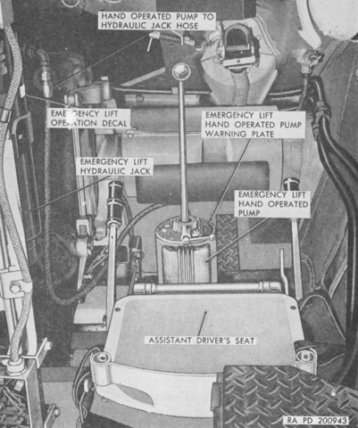
The mounting base for the hand-operated emergency lift pump was welded to the torsion bar cover in front of the assistant driver. Moving the pump lever back and forth forced hydraulic oil into the emergency lift hydraulic jack. As this jack extended, the emergency lift cable was drawn in, consequently raising the moldboard to the carrying position. (Picture from TM 9-7408 Operation, Organizational Maintenance, and Ordnance Field and Depot Maintenance Earth Moving Tank Mounting Bulldozer M4.)
