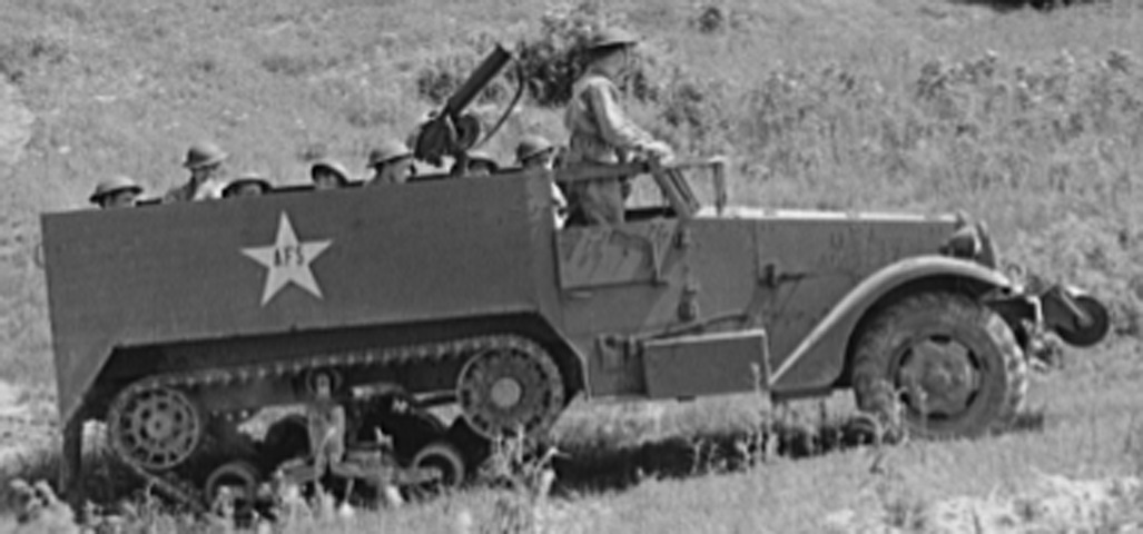
Half-track Personnel Carrier M3.
The longer body on this vehicle is obvious when the rear is compared to that of the half-track car M2. This early vehicle is fitted with the large fender-mounted headlights, a water-cooled machine gun, and the idler wheel is unsprung. (Picture taken June 1942 by Alfred T. Palmer; available from the Library of Congress.)
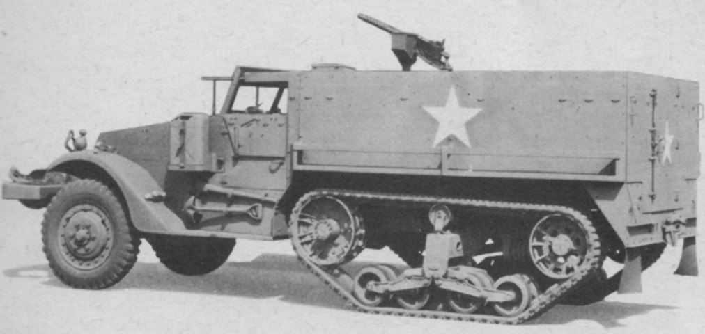
This later vehicle is fitted with the demountable headlights, mine racks, 5-gallon (19L) water containers on each side of the cowl, and a double-coil idler spring. (Picture from TM 9-710 Basic Half-Track Vehicles (White, Autocar, and Diamond T).)
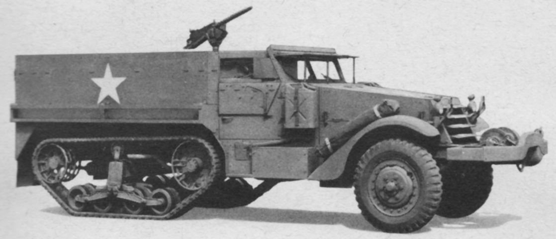
Installation of the winch can be contrasted with that of the roller above. (Picture from TM 9-710 Basic Half-Track Vehicles (White, Autocar, and Diamond T).)
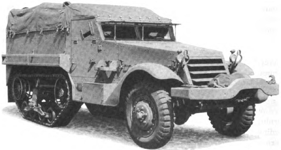
A canvas cover has been installed over the passenger compartment of this vehicle. (Picture from TM 9-2800 Standard Military Motor Vehicles.)
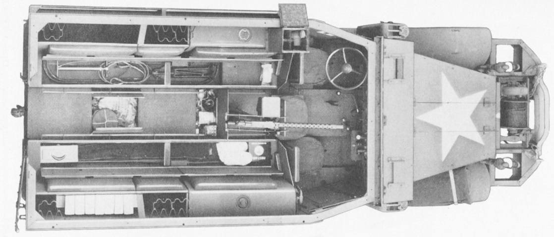
All stowage compartments on this half-track are open. The seats have stowage under them, as well as the floor. The vehicle's fuel tanks are near the front, and a .30cal machine gun is mounted on its pedestal. Rifle clips are also visible around the edge of the passenger compartment. This vehicle is fitted with the small, demountable headlights. (Picture from TM 9-710 Basic Half-Track Vehicles (White, Autocar, and Diamond T).)
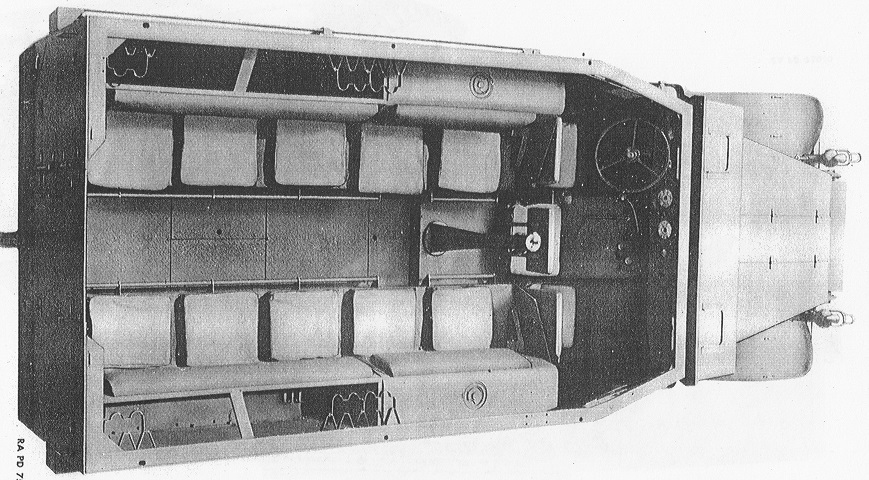
The stowage compartments are closed in this view, showing us the seating arrangement with three men in the cab and ten in the rear. Rolled blankets could be stowed in the seat cushions. (Picture from Standard Nomenclature List G-102.)
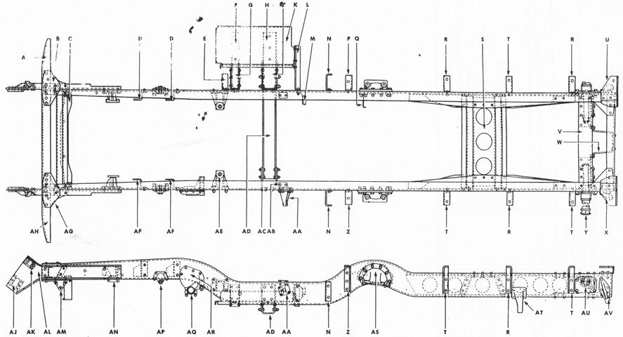
The chassis frame is drawn in plan and elevation. (Picture from Standard Nomenclature List G-102.)
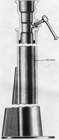
A cross-section of the pedestal mount M25 is shown in this image. The cradle pintle clamping screw near the top allowed the machine gun cradle to be locked at any point of traverse. (Picture from TM 9-710/TO 19-75A-77.)
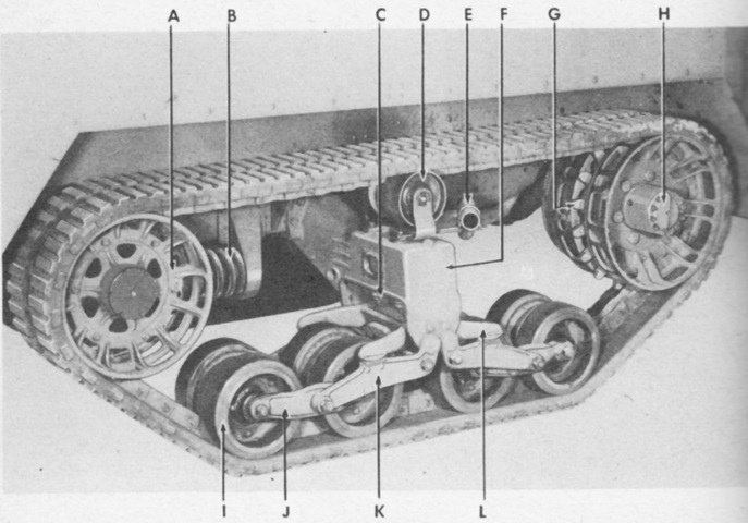
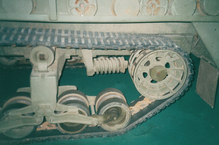
Details of the rear suspension are visible in this picture. This vehicle is fitted with the double-coil spring-loaded idler wheel. A. Idler wheel. B. Idler spring. C. Volute spring. D. Bogie upper roller. E. Tail pipe. F. Bogie and frame assembly. G. Track driving sprocket. H. Rear axle shaft flange. I. Bogie roller. J. Bogie frame. K. Bogie arm. L. Crab. (Picture from TM 9-710 Basic Half-Track Vehicles (White, Autocar, and Diamond T).)
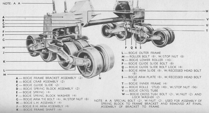
The bogies have been dismounted from the vehicle, and parts of the assembly are detailed here. (Picture from TM 9-710 Basic Half-Track Vehicles (White, Autocar, and Diamond T).)
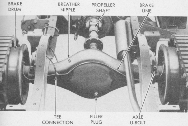
The Timken 56410-BX-67 rear driving axle is illustrated in this picture. It was a single-reduction, full-floating type with a spiral bevel drive gear. (Picture from TM 9-710 Basic Half-Track Vehicles (White, Autocar, and Diamond T).)
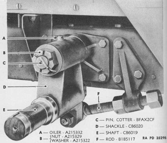
The track adjusting idler shaft and bracket are seen with the idler wheel removed. This is an earlier half-track with an unsprung idler. Tension was adjusted by loosening the anchor pin nuts for the idler shackle, and loosening either the upper or lower bronze nut on the adjusting rod, after which the opposite bronze nut would be tightened. (Picture from TM 9-1710C Ordnance Maintenance--Chassis and Body for Half-track Vehicles.)
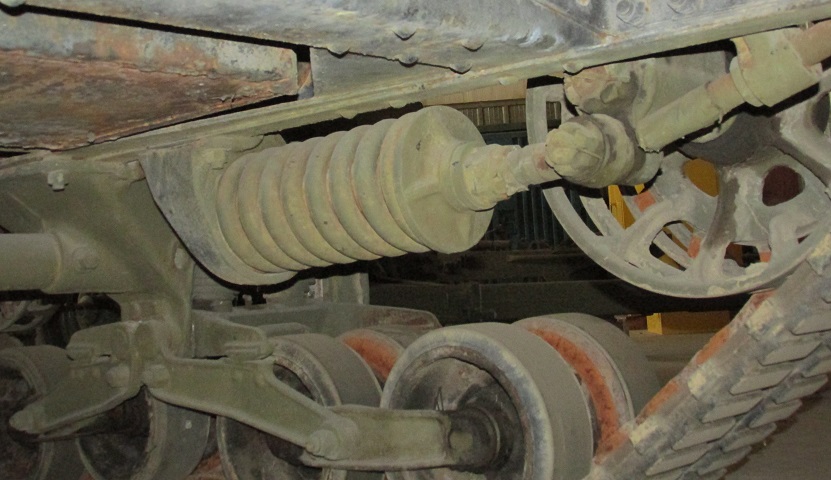
Details of the idler wheel and double-coil spring can be seen here. The spring kept the track under tension while allowing the idler wheel to move back and forth depending on changes in track tension or upon the overcoming of obstacles. After setting the track tension, a covering such as tape was applied to the threads of the idler stop screw to prevent damage, and the screw was adjusted until 1.75-2" (4.45-5cm) of clearance between the idler bracket and screw was obtained.
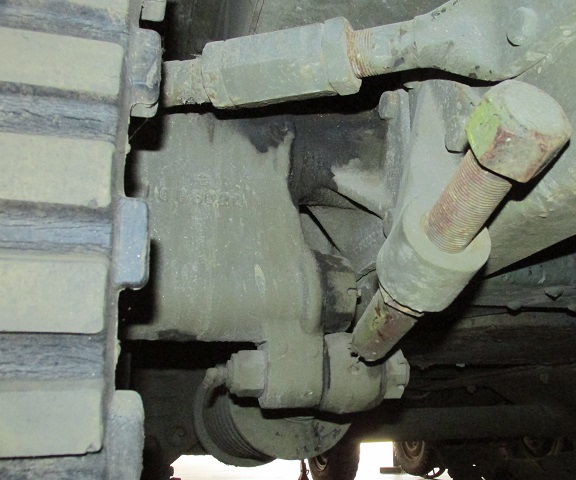
A rear view of the idler stop screw is provided here. The joint between the spring and the idler bracket is better seen in this image as well. The turnbuckle at the top of the image is the idler post brace.
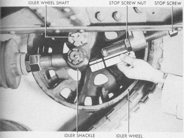
The method of checking the clearance between the idler stop screw and the idler shackle is shown. (Picture from TM 9-710 Basic Half-Track Vehicles (White, Autocar, and Diamond T).)
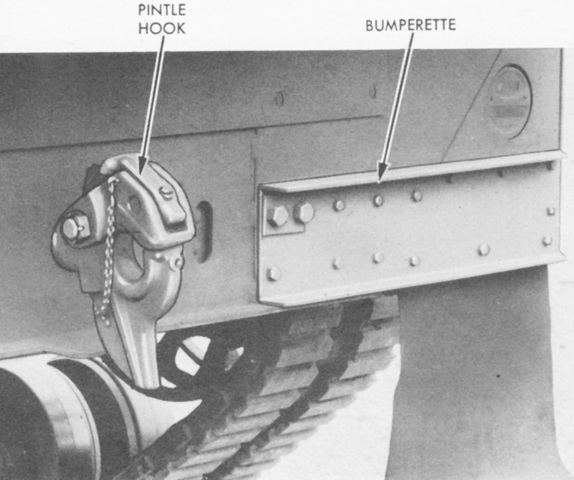
The M2 and M3 half-tracks had twin bumperettes made out of channel steel and attached to the rear of the chassis. Half-tracks made by International Harvester mounted bumpers of a different design. (Picture from TM 9-710 Basic Half-Track Vehicles (White, Autocar, and Diamond T).)
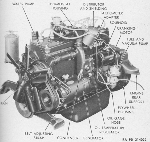
The left side of the White 160AX engine is shown here. (Picture from TM 9-710 Basic Half-Track Vehicles (White, Autocar, and Diamond T).)
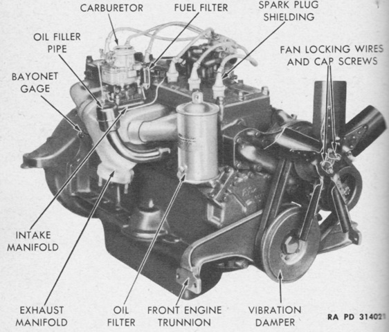
The right side of the engine is shown here. (Picture from TM 9-710 Basic Half-Track Vehicles (White, Autocar, and Diamond T).)
Two 30gal (110L) fuel tanks manufactured by Mitchel Metal and Goodyear were positioned in the rear compartment and covered with a self-sealing composition. The filler cap featured a breather valve so that air could replace fuel as it was used, and a flame arresting screen was mounted at the opening of the filler cap in case a spark occurred when filling the tank. (Picture from TM 9-710 Basic Half-Track Vehicles (White, Autocar, and Diamond T).)
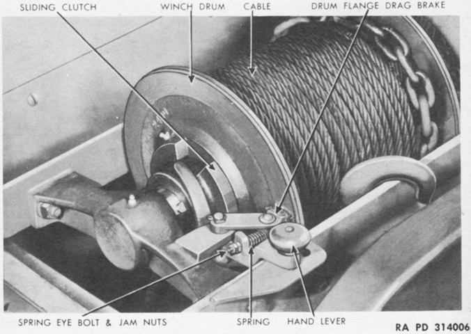
Details of the Tulsa Model 18G are illustrated in this image. It was equipped with a safety brake that would hold the load whenever power was cut off from the winch. Forward or reverse direction for the winch was determined by the position of the power take-off lever in the cab. Once the cable was hooked to a load, the winch drum clutch was engaged, the vehicle clutch pedal was depressed, the power take-off lever was shifted into forward, and then the vehicle clutch pedal was slowly released. The winch speed was then determined by the vehicle accelerator pedal. (Picture from TM 9-710 Basic Half-Track Vehicles (White, Autocar, and Diamond T).)
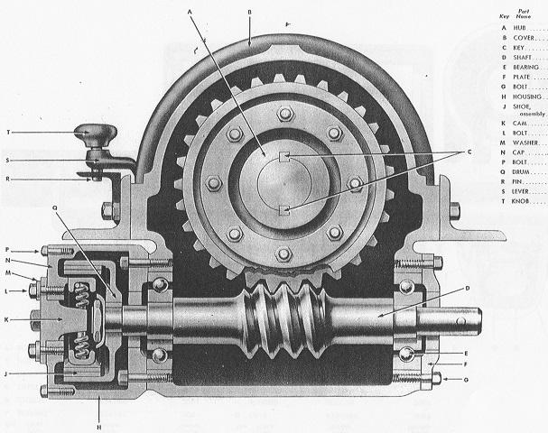
A sectionalized view of the winch is shown here, illustrating how the power take-off engaged the winch gearing. (Picture from Standard Nomenclature List G-102.)
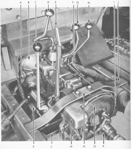
This view is looking forward into the cab footwell with the floorplates removed. The propeller shaft brake assembly was a brake disc that served as the vehicle's parking brake. The legend is as follows: A. Clutch release lever. B. Bell housing. C. Power take-off shift lever. D. Transmission shift lever. E. Hand brake lever. F. Shift lever connecting link. G. Transfer case shift lever. H. Front axle shift lever. I. Speedometer cable coupling. J. Transmission support spring. K. Power take-off assembly. L. Transmission case protector. M. Propeller shaft brake assembly. N. Spring pressure plate. O. Brake disc. P. Propeller shaft. (Picture from TM 9-710 Basic Half-Track Vehicles (White, Autocar, and Diamond T).)
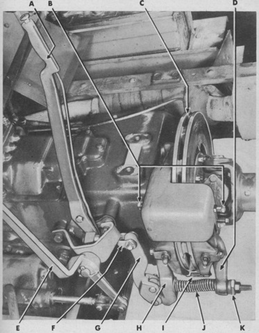
A closer look at the propeller shaft brake is given in this picture. A. Hand brake lever. B. Brake shoe adjusting set screws. C. Brake disc. D. Rear brake lever arm. E. P.T.O. shift lever. F. Pull rod. G. Operating lever. H. Front axle lever arm. I. Brake shoe spring. J. Lever release spring. K. Spherical adjusting nut. (Picture from TM 9-710 Basic Half-Track Vehicles (White, Autocar, and Diamond T).)
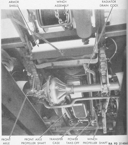
The underside of the front axle, including the power take-off shaft to the winch, is shown here. (Picture from TM 9-710 Basic Half-Track Vehicles (White, Autocar, and Diamond T).)

The small headlights could be dismounted by unscrewing the locating plunger, which would release the locating pin from the headlight's mounting shaft. A chain-tethered plug was provided to seal the opening in the mounting bracket when the headlight was absent. Blackout marker lights were found atop the sealed-beam headlights. (Picture from TM 9-710 Basic Half-Track Vehicles (White, Autocar, and Diamond T).)
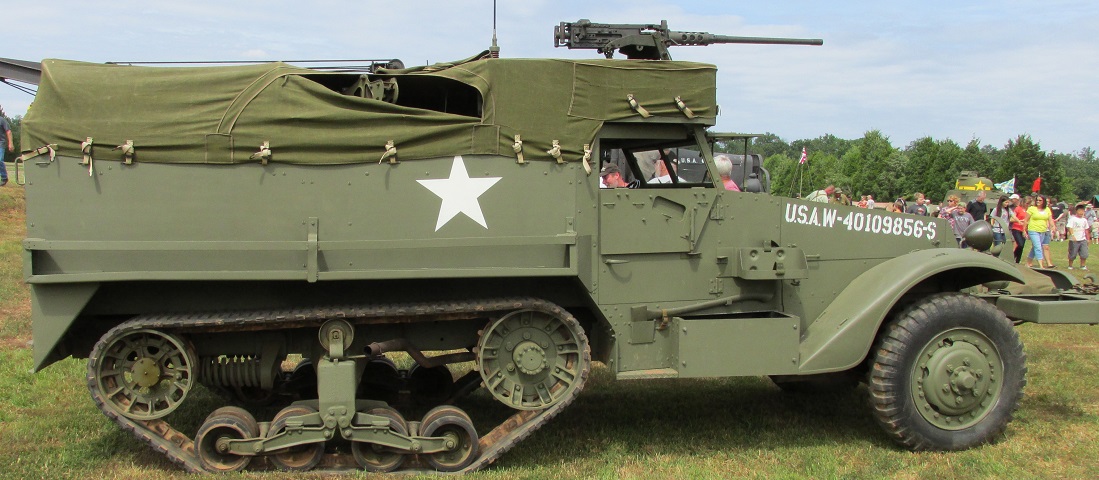
This M3A1 is armed with a .50cal machine gun mounted on the M49 ring mount above the cab, but the mount and passenger compartment are covered. A mount for a .30cal MG can be seen peeking through where the canvas cover has parted. This vehicle retains the large fender-mounted headlights, and mine racks are mounted on the sides of the passenger compartment. The fenders are thick in cross-section, and the batteries are housed in the box below the right-side door. This half-track has the double-coil spring loaded idler wheel. The shutter in the folding window armor of the doors is mounted on the outside of the armor when it is raised. On half-tracks built by International Harvester, the shutter would be on the inside of the armor when it is in the raised position; i.e., the shutter mounting would be visible when the armored flap is folded down like in this view.
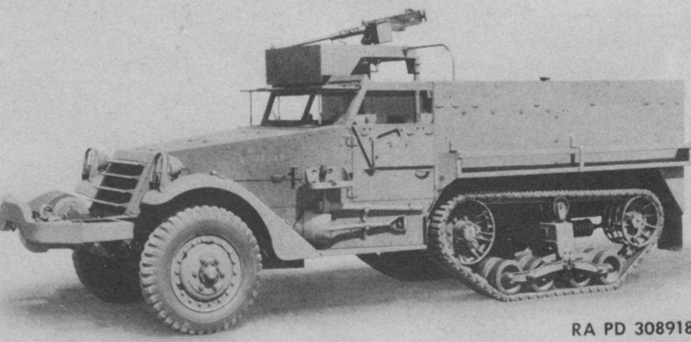
Details of the machine gun mount without the canvas cover can be seen in this image. (Picture from TM 9-710 Basic Half-Track Vehicles (White, Autocar, and Diamond T).)
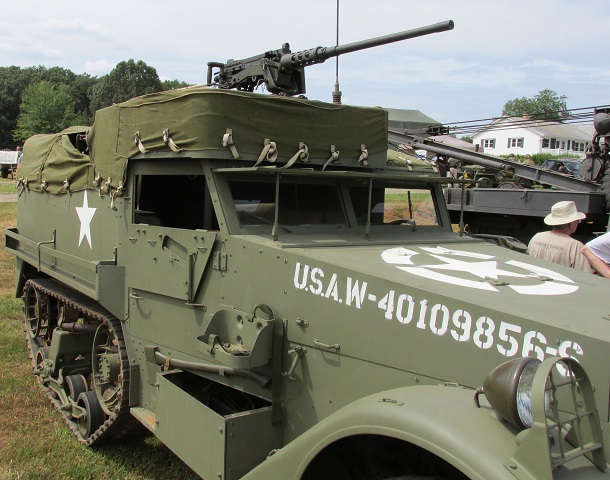
The .50cal MG ring mount did not stretch all the way across the driver's compartment. A stowage rack for a water or fuel can can be seen above the axe on the passenger door, and details of the early headlight mounting can be seen.
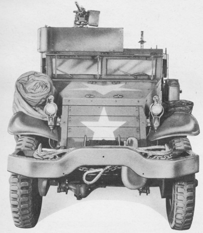
The offset nature of the machine gun mount is easily seen in this front view. (Picture from TM 9-710 Basic Half-Track Vehicles (White, Autocar, and Diamond T).)
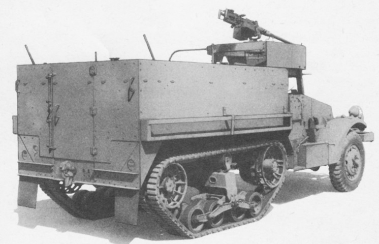
The flush rear of the passenger compartment, rear door, and details of the rear of the machine gun mount are pertinent highlights from this angle. (Picture from TM 9-710 Basic Half-Track Vehicles (White, Autocar, and Diamond T).)
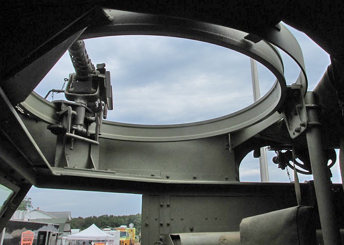
The interior of the ring mount M49 with its machine gun rail and carriage is shown here.
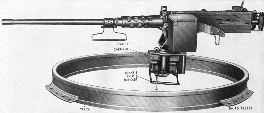
The machine gun ring mount M49 is shown here with a .50cal machine gun mounted. The .30cal M1919A4 could also be used. (Picture from TM 9-710/TO 19-75A-77.)
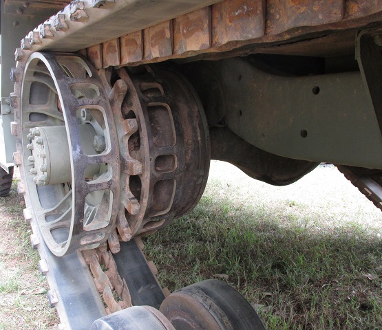
Details of the drive sprocket can be seen in this image.
This half-track is fitted with the late-production double-coil spring loaded idler wheel. The earlier single-coil mechanism was a quick-fix until the double-coil design could be put into production.
