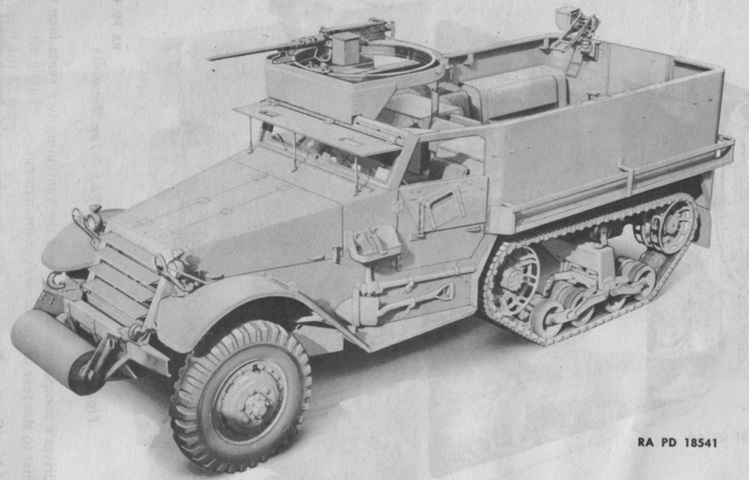
Half-track Car M9A1.
Although analogous to the half-track car M2A1, the M9A1 featured a personnel-carrier-length body and lacked the side ammunition stowage compartments. The ring mount for the .50cal MG dominates the front right corner of the vehicle, and a pintle mount for a .30cal MG can be seen in the rear of the passenger compartment. (Picture from TM 9-707 Basic Half-Track Vehicles (IHC).)
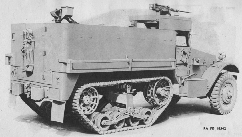
Unlike half-track cars built by White, Autocar, and Diamond T, the M9A1 possessed a rear door and rounded rear corners. Note also the thin cross-sectional view of the front fenders. (Picture from TM 9-707 Basic Half-Track Vehicles (IHC).)
The top support of the mine racks on IHC half-tracks attached to the rear of the body, as opposed to M2- and M3-based vehicles. IHC half-tracks also were fitted with distinctive rear bumperettes. (Picture from TM 9-707 Basic Half-Track Vehicles (IHC).)
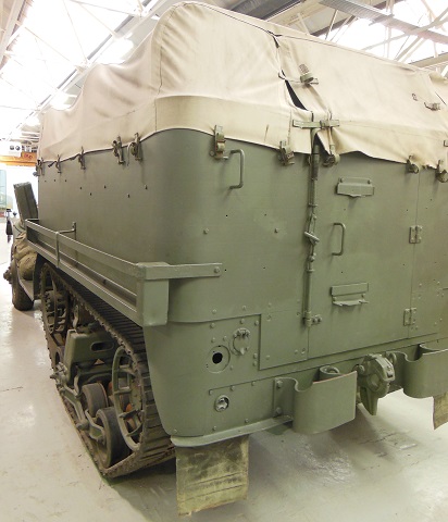
The attachment of the mine racks can be better discerned in this picture. The rolled nature of the armor of the IHC half-tracks necessitated additional support for the mine racks. (Picture courtesy 8Hussar Ottawa.)
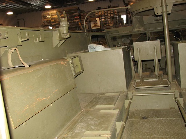
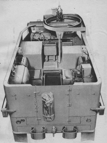
Although lacking seat cushions, the position of the personnel can be gleaned from this image. The driver sat left front, there were two other men in the cab beside him, one man sat behind the central man in the cab (his seat back is folded down), and on each side of the rear compartment were three inward-facing seats that used the fuel tanks for backrests. (Picture courtesy 8Hussar Ottawa.)
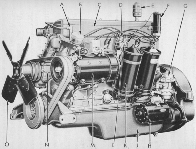
The IHC half-tracks used an overhead-valve engine produced by that company. The RED-450-B could hold 10.5 quarts (~10L) of oil, and the engine weighed 1250lb (567kg) with accessories. A. Crankcase ventilator. B. Oil filler cap. C. Valve rocker-arm cover. D. Distributor. E. Cylinder breather. F. Ignition coil. G. Fuel pump. H. Starting motor. J. Oil pan. K. Oil filters. L. Oil level gage. M. Generator. N. Water pump. O. Fan. (Picture from TM 9-707 Basic Half-Track Vehicles (IHC).)
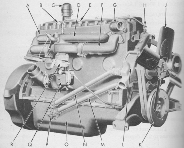
A. Cylinder head. B. Engine temperature warning unit. C. Cylinder head breather. D. Intake manifold. E. Engine temperature sending unit. F. Exhaust manifold. G. Thermostat housing. H. Crankcase breather. J. Fan assembly. K. Vibration damper. L. Water pump. M. Oil cooler outlet. N. Oil cooler inlet. O. Oil pan. P. Oil cooler manifold. Q. Carburetor. R. Governor. (Picture from TM 9-707 Basic Half-Track Vehicles (IHC).)
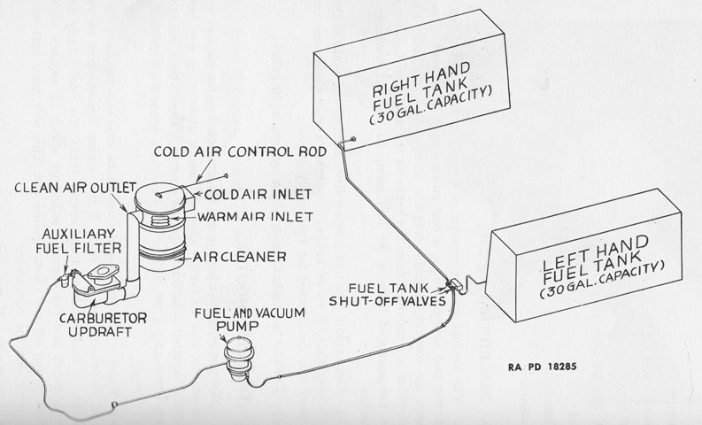
This schematic shows the layout of the fuel system. Either tank could be selected for the delivery of fuel. (Picture from TM 9-707 Basic Half-Track Vehicles (IHC).)
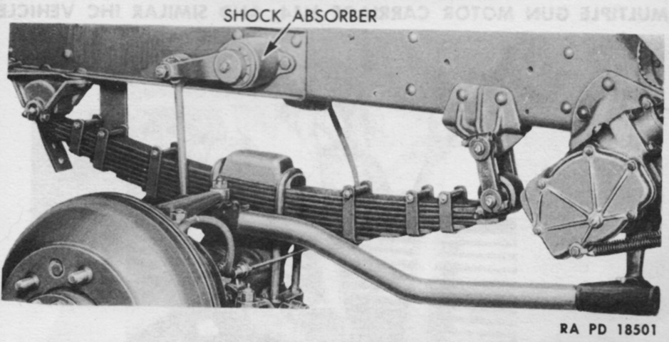
The front suspension is shown here. A double-acting shock absorber was mounted on each side. (Picture from TM 9-707 Basic Half-Track Vehicles (IHC).)
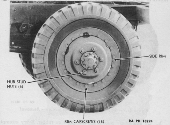
The combat-type front wheels were comprised of a ventilated steel disc and a side retainer rim that was secured by 18 retaining capscrews. (Picture from TM 9-707 Basic Half-Track Vehicles (IHC).)
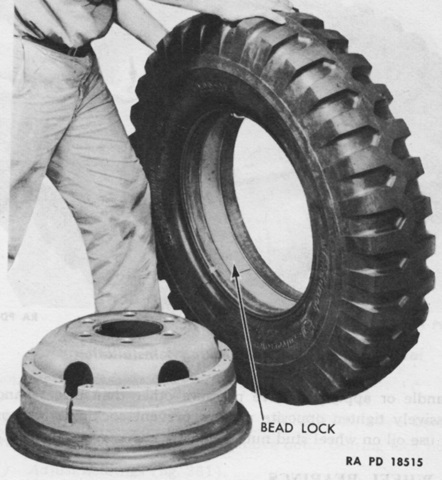
Bead locks were installed between the tires' beads. These were flexible steel bands attached to several flanged metal blocks, and they prevented the beads from being forced inwards should it be necessary to use the tires in a deflated state. (Picture from TM 9-707 Basic Half-Track Vehicles (IHC).)
