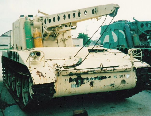
Light Recovery Vehicle M578.
The M578's relation to the M107 and M110 is obvious when their hulls are compared. (Picture from TM 9-2350-238-10.)
The vehicle is shown here from the right front. (Picture from TM 9-2350-238-10.)
The rear is labeled in this image. A radio antenna angles up from the left rear of the cab roof. (Picture from TM 9-2350-238-10.)
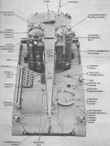
The positioning of the various crew hatches and cupolas can be seen from above. (Picture from TM 9-2350-238-10.)
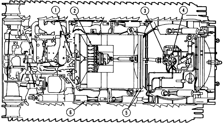
Major internal components are drawn in this top-down cutaway. 1. Auxiliary drive. 2. Fan. 3. Hydraulic pump. 4. Slip ring. 5. Torsion bar. 6. Lockout cylinder. (Picture from TM 9-2350-238-10 C4.)
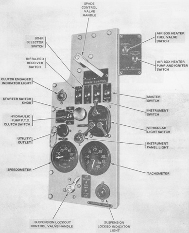
The driver's position was similar to that found in the related self-propelled ordnances, but the spade control was moved from the rear near the spade to the driver's switch panel. (Picture from TM 9-2350-238-10.)
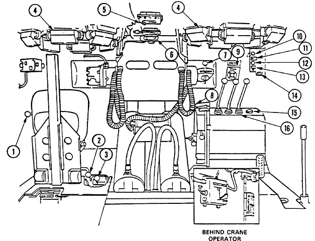
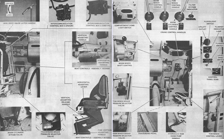
The crane operator and rigger's controls are here, looking from behind their seats towards the front of the cab. 1. Vertical adjusting handle, operator or rigger seat. 2. Horizontal adjustment knob, operator or rigger seat. 3. Traversing brake pressure selector valve. 4. Periscope M17. 5. Dome light switch. 6. Gas-particulate air purifier switch. 7. Boom winch shift control lever. 8. Tow winch shift control lever. 9. Load rating capacities instruction plate. 10. Utility outlet. 11. Floodlight switch. 12. Flasher indicator lamp. 13. Flasher switch. 14. Level wind switch. 15. Filter bypass indicator light. 16. Boom cylinder control handle. (Picture from TM 9-2350-238-10 C4.)
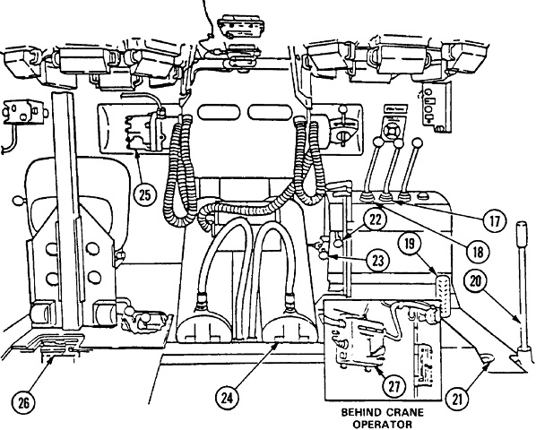
17. Tow winch control handle. 18. Boom winch control handle. 19. Traversing foot pedal. 20. Hydraulic ram hand pump handle. 21. Quick disconnect coupling with cap. 22. Tow winch brake pressure selector valve. 23. Boom winch brake pressure selector valve. 24. Boom cylinder. 25. Boom winch hydraulic motor. 26. Boom cylinder bypass valve. 27. Intercommunication control box. (Picture from TM 9-2350-238-10 C4.)
The cab interior is presented here in photographs. (Picture from TM 9-2350-238-10.)
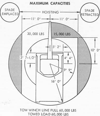
The hoisting and tow winching load rating capacities were calculated with the vehicle being on relatively level ground, having the suspension locked out, and with the load being lifted from directly under the boom tip. The schematic shows the areas where it was permissible to position the boom during different load conditions. When lifting a load up to 15,000lb (6,800kg), the shaded area was safe. When lifting between 15,000-30,000lb (6,800-14,000kg), the boom was to be positioned within the white areas. When lifting 15,000lb (6,800kg) or less, the boom could be raised to any elevation throughout the cab turning range. (Picture from TM 9-2350-238-10.)
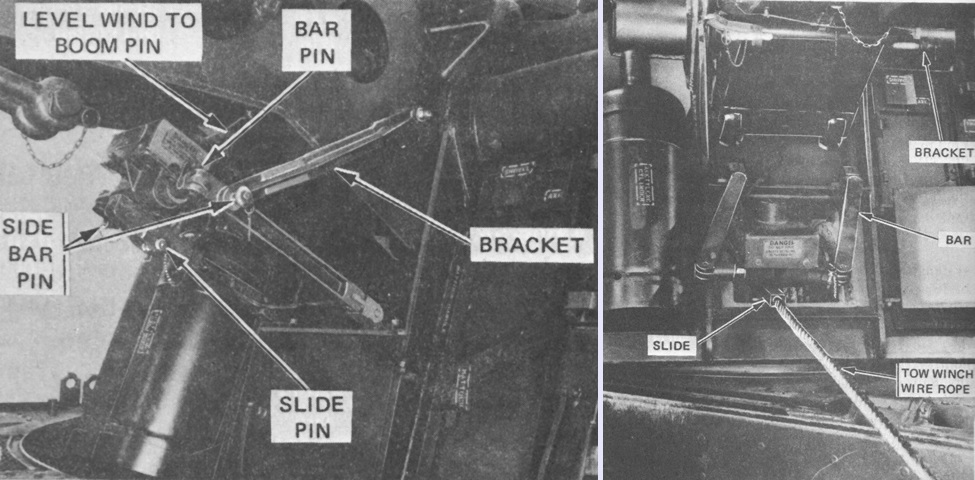
The tow winch's level wind system is shown stowed on the left, and on the right in operation with the wire rope played out. The level wind system used two sensing switches to automatically traverse the cab whenever the tow winch cable started to wander to one side or the other on its drum, thereby assuring a perfect wire rope layup. After assembly, the system had to be turned on by a switch in the cab. (Picture from TM 9-2350-238-10.)
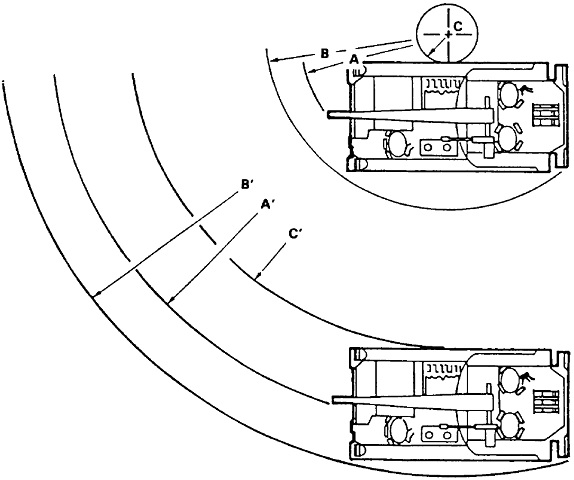
The vehicle used clutch-brake steering in forward ranges 1 and 2 and reverse range 1, with the vehicle pivoting around a locked track, while geared steering was used in forward ranges 3 and 4 and reverse range 2. For clutch-brake steering, the minimum for radius A is 13'5" (4.09m), B is 16'10" (5.13m) and C is 30" (76cm). For geared steering in forward range 3 at 15mph (24kph), the minimum for A' is 36'2" (11.0m), B' is 41' (12.5m) and C' is 29' (8.8m). (Picture from TM 9-2350-238-10 C4.)
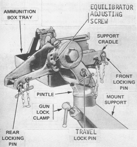
Details of the caliber .50 machine gun mount 7046650 found on the rigger's cupola are seen here with the gun and ammunition absent. (Picture from TM 9-2350-238-10.)
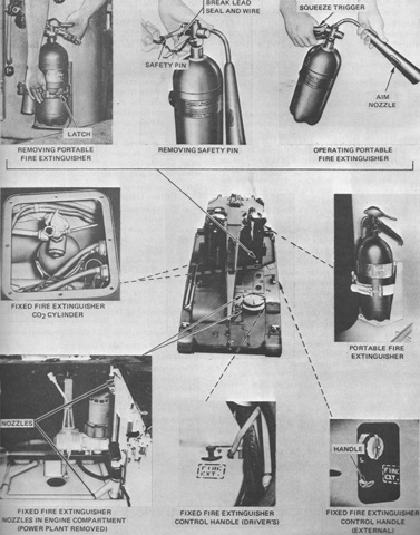
The fixed fire extinguisher system was composed of a 10lb (4.5kg) CO2 cylinder installed in each side of the hull to the cab's front; these were routed to the engine compartment. Both cylinders were discharged simultaneously when either of the the remote control handles found in the driver's compartment or on the left fender were pulled. In addition, two 5lb (2.3kg) portable CO2 extinguishers were stowed on the cab, one inside behind the rigger and a second on the cab's exterior left front. (Picture from TM 9-2350-238-10.)
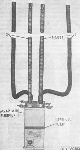
Two gas-particulate filter units M8A3 were used in conjunction with the crews' protective masks M14 to protect against toxic gases or extremely dusty conditions. The M8A3 used an air purifier M2A2, and one was installed in the cab on the boom cylinder as well as on the floor in front of the driver. Up to four personnel could be accommodated by each unit, but the system would not protect against carbon monoxide. (Picture from TM 9-2350-238-10.)
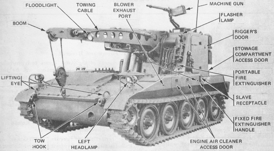
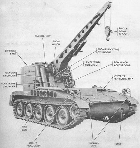
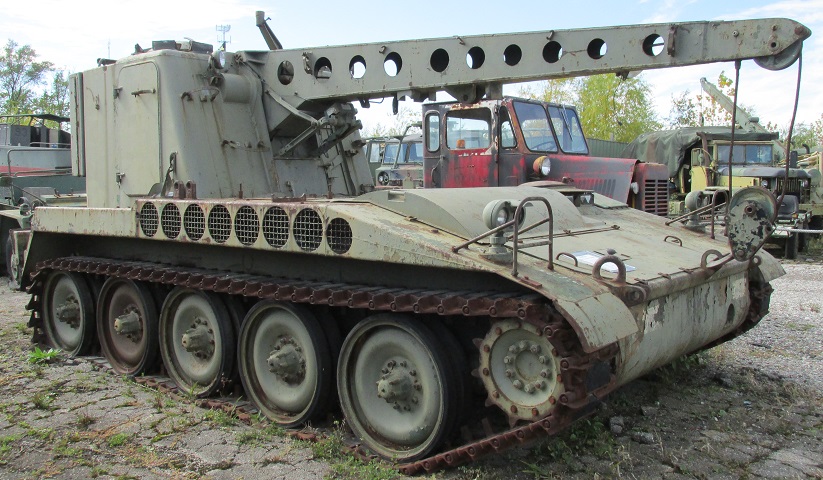
The parentage of the M578's hull is immediately obvious once it is compared to the M107 and M110 artillery pieces. The armored rotating cab replaced the ordnance, but the hulls are the same. The cylinder on the right side of the cab is for oxygen; an acetylene cylinder is placed just inboard of the oxygen tank. The placement of the 60,000lb (27,000kg) winch access door is just below the crane boom in the cab front. Some of the M17 periscopes in the crane operator's cupola can be seen above the oxygen tank and floodlight. The indentation in the lower left bow is a step for the driver.
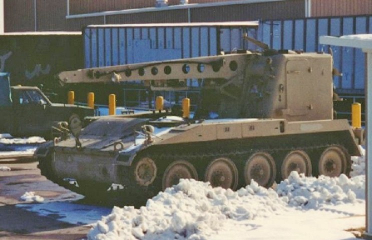
A large door dominated each side of the cab. Pioneer tools were stowed on the front slope of the cab to the left of the crane boom, and a flasher light was perched above this stowage near the roof. The mount for the .50cal machine gun can be seen on the left-hand vision cupola, under which sat the rigger. The doors in the fender above the second and third road wheels provided access to the engine's air cleaners. The two 10' (3m) tow cables stowed on the vehicle could safely handle 110,000lb (50,000kg). (Photo by Richard S. Eshleman.)
The rounded engine cover and the handle on the door for the tow winch can better be seen in this image.
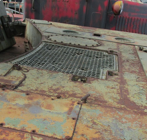
A close-up of the engine deck including the fan well cover is provided here.
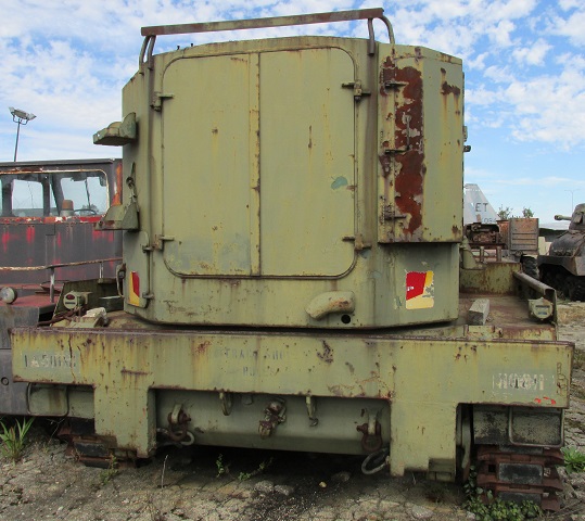
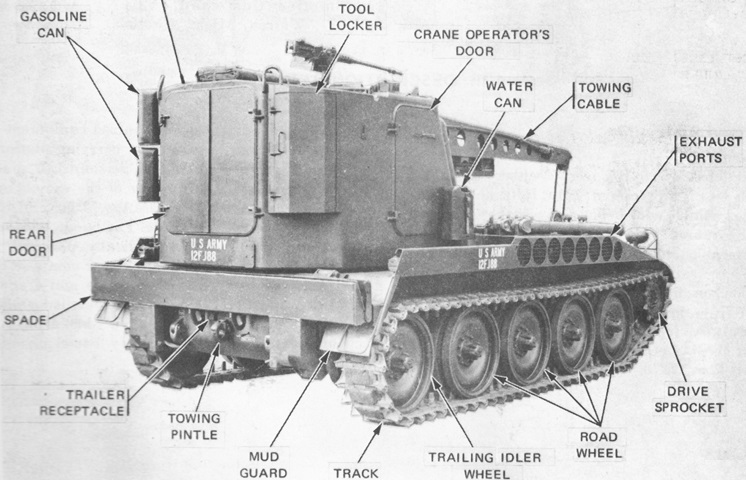
The cab's twin rear doors are shown here. On the left side of the cab rear were shelves for stowage of two gasoline cans, and a tool locker was mounted on the opposite corner of the cab rear. The rear stabilizing spade can be seen just under the cab in its raised position.
