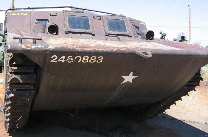
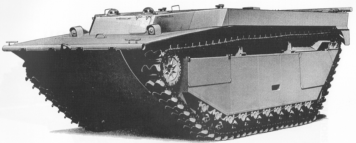
Landing Vehicle, Tracked, Mark 4 belonging to the US Army Ordnance Museum.
This vehicle features the unarmored cab with two large bottom-hinged glass windows in the front. Mooring ties are mounted at each corner of the hull, and the track grousers that propelled the vehicle in water are obvious. Headlight mounts are on the front slope, and an antenna mount is behind the starboard headlight.
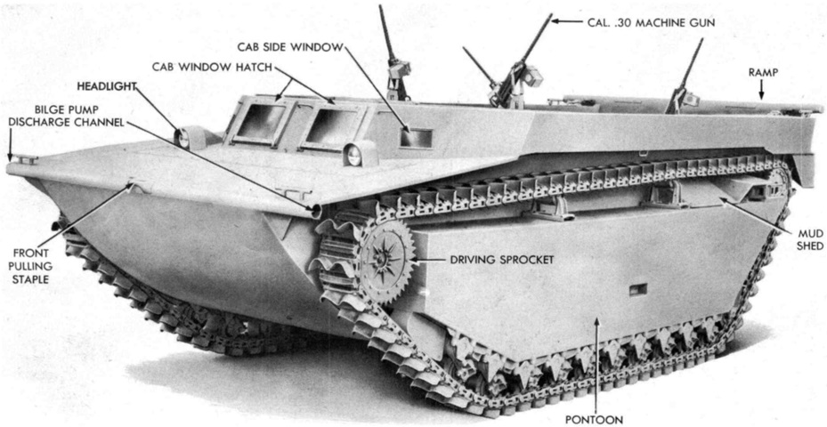
A wider view of a tractor with the unarmored cab is shown here. (Picture from TM 9-776 Landing Vehicle, Tracked, Mk.IV LVT(4).)
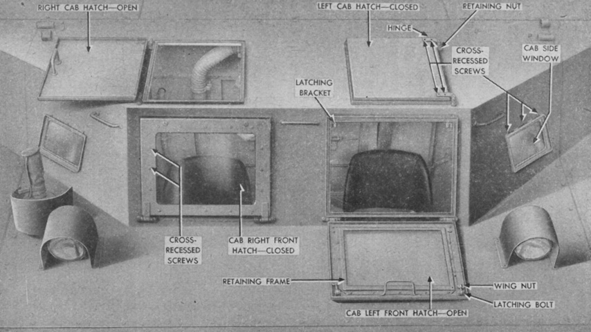
The unarmored cab was made from heavy-gauge steel, and the operation of the shatterproof front windows is shown here. Modified cabs had the front hatch hinges reversed so that the hatches opened upward. (Picture from TM 9-775 Tracked Landing Vehicle Mk 4 (LVT(4)) Tracked Landing Vehicles (Armored) Mk 4 (LVT(A)(4)) and Mk 5 (LVT(A)(5)).)
The large pontoon inside the track run provided displacement for flotation; was a mounting point for the road wheels, idler wheel, and track return rollers; and could also be used for stowage. This vehicle has bows for a canvas cover mounted, but the cover itself is absent.
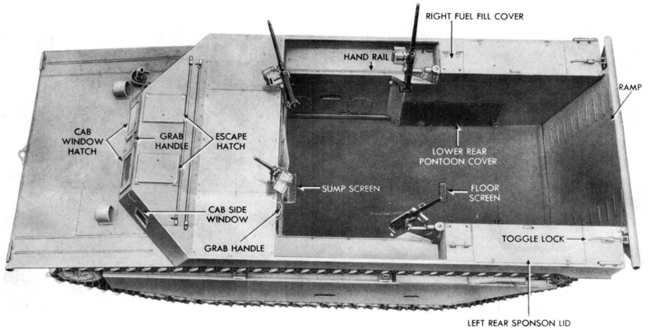
The rear loading ramp allowed a much more protected egress than jumping over the tall sides of earlier tractors. The relocation of the engine to behind the cab also increased the size of the cargo compartment from 364ft³ (10.3m³) in the LVT2 to 541.3ft³ (15.33m³) in the LVT4. (Picture from TM 9-776 Landing Vehicle, Tracked, Mk.IV LVT(4).)
The larger and more efficient cargo compartment can be contrasted to that found on the LVT2. (Picture from TM 9-776 Landing Vehicle, Tracked, Mk.IV LVT(4).)
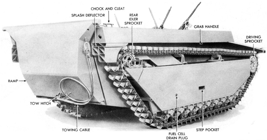
The ramp of this vehicle is lowered, and forward is the engine room. The ramp was operated by a hand winch that, thanks to torsilastic springs in late-production vehicles, required no more than 15 pounds (6.8kg) of pressure at the handle to operate. Splash deflectors are just behind each track. (Picture from TM 9-776 Landing Vehicle, Tracked, Mk.IV LVT(4).)
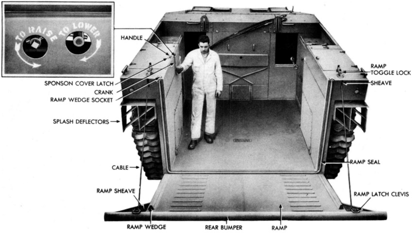
The ramp was raised and lowered via a winch with a crank handle which was installed in the left rear sponson box. (Picture from TM 9-776 Landing Vehicle, Tracked, Mk.IV LVT(4).)
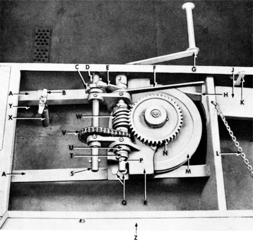
The winch found on early tractors was a hand-operated, two-speed, ratchet and pawl type. A shorter crank was also provided in the event that it was necessary to operate the winch from the top of the sponson box. The ballast control valve shown is the early type. A. Winch mounting bracket. B. Ballast valve pull handle. C. Ratchet. D. Crank pin. E. Upper pawl. F. Lower pawl handle. G. Crank. H. Cable. J. Cable guard. K. Lid latch. L. Sponson lid chain. M. Drum sheave. N. Worm gear. P. Worm shaft. Q. Frame retaining bolts. R. Winch frame. S. Countershaft. T. Collar. U. Bearing. V. Roller chain. W. Worm. X. Ballast valve vent pipe. Y. Left rear sponson box. Z. Left rear sponson lid. (Picture from TM 9-776 Landing Vehicle, Tracked, Mk.IV LVT(4).)
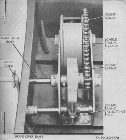
Later-production machines had a hand-operated, two-speed, brake and drum winch for the rear ramp. As noted, instead of the plain ramp hinge found on the ratchet and pawl winch-equipped machines, the ramp on late vehicles featured a torsilastic hinge to help with operating the ramp. (Picture from TM 9-775 Tracked Landing Vehicle Mk 4 (LVT(4)) Tracked Landing Vehicles (Armored) Mk 4 (LVT(A)(4)) and Mk 5 (LVT(A)(5)).)
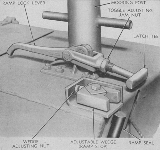
A hand-operated toggle lock was installed on top rear of each sponson box. These secured the ramp against its seal and provided adjustment to ensure the seal remained watertight. Clevises on the ramp bumper engaged the locks. (Picture from TM 9-775 Tracked Landing Vehicle Mk 4 (LVT(4)) Tracked Landing Vehicles (Armored) Mk 4 (LVT(A)(4)) and Mk 5 (LVT(A)(5)).)
A deeper look into the rear compartment is provided here. (Picture from TM 9-776 Landing Vehicle, Tracked, Mk.IV LVT(4).)
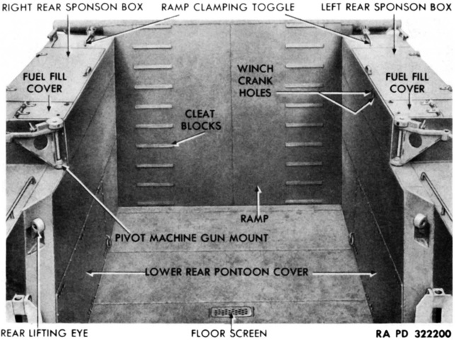
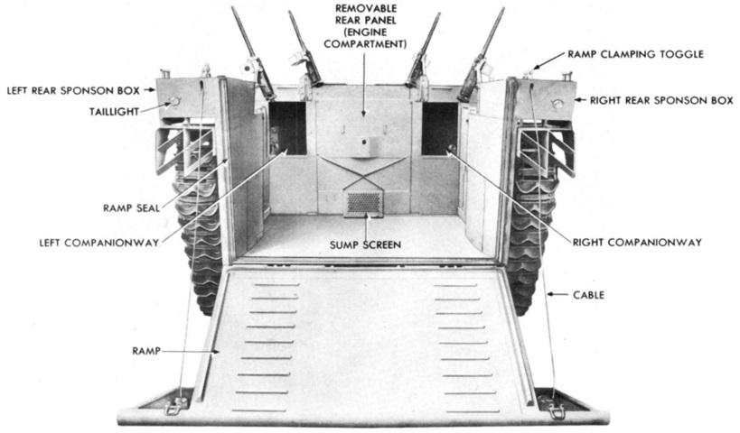
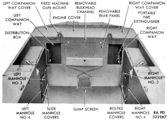
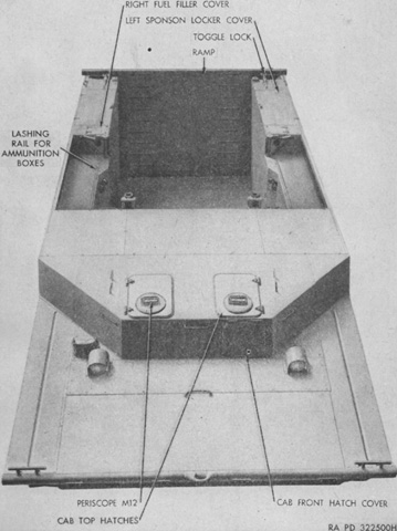
The rear of the cargo compartment is labeled in this image. (Picture from TM 9-776 Landing Vehicle, Tracked, Mk.IV LVT(4).)
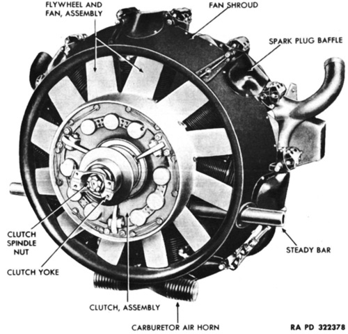
The flywheel end of the engine, seen here, was referred to as the front. Bore and stroke were 5.125" and 4.625" (13.02cm and 11.75cm), respectively, for a displacement of 667.86in³ (10.944L). Its compression ratio was 6.1:1. (Picture from TM 9-776 Landing Vehicle, Tracked, Mk.IV LVT(4).)
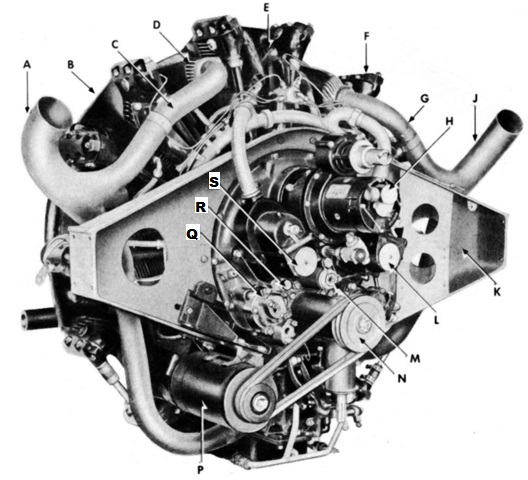
The engine is shown from the left rear. A. Left exhaust stack. B. Spark plug baffle. C. Exhaust pipe. D. Intercylinder baffle. E. Cylinder no. 1. F. Rocker box. G. Exhaust pipe. H. Cranking motor. J. Right exhaust stack. K. Engine support beam. L. Right magneto. M. High pressure oil screen. N. Generator drive pulley. P. Generator. Q. Oil pressure and scavenger pump. R. Scavenger oil screen. S. Left magneto. (Picture from TM 9-776 Landing Vehicle, Tracked, Mk.IV LVT(4).)
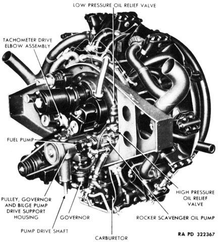
The right rear of the engine is labeled in this picture. It was 42 ⅜" (107.63cm) in overall diameter and ~1,100lb (~500kg) with accessories. (Picture from TM 9-776 Landing Vehicle, Tracked, Mk.IV LVT(4).)
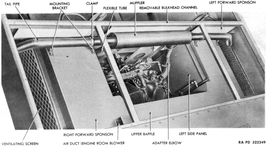
The engine room is viewed from above in this picture. (Picture from TM 9-776 Landing Vehicle, Tracked, Mk.IV LVT(4).)
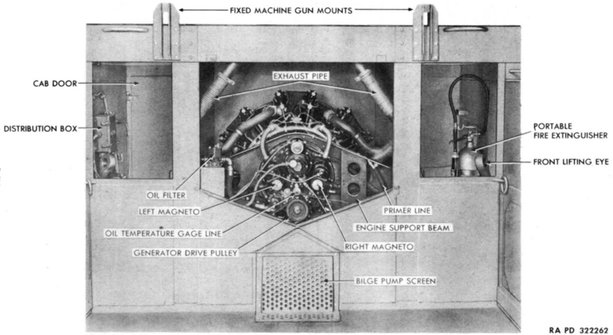
The engine room with its rear panel removed is shown here from the passenger compartment. (Picture from TM 9-776 Landing Vehicle, Tracked, Mk.IV LVT(4).)
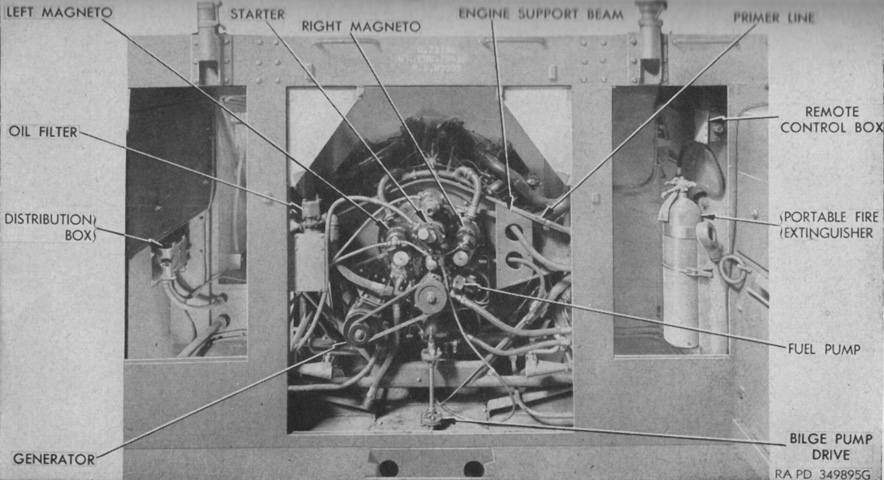
More paneling has been removed in this image. (Picture from TM 9-775 Tracked Landing Vehicle Mk 4 (LVT(4)) Tracked Landing Vehicles (Armored) Mk 4 (LVT(A)(4)) and Mk 5 (LVT(A)(5)).)
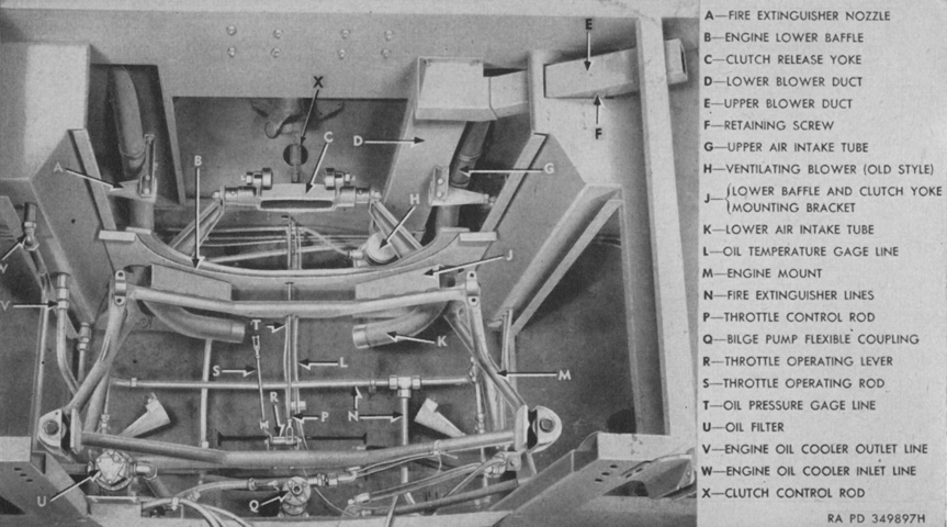
The engine compartment is labeled with the engine removed. (Picture from TM 9-775 Tracked Landing Vehicle Mk 4 (LVT(4)) Tracked Landing Vehicles (Armored) Mk 4 (LVT(A)(4)) and Mk 5 (LVT(A)(5)).)
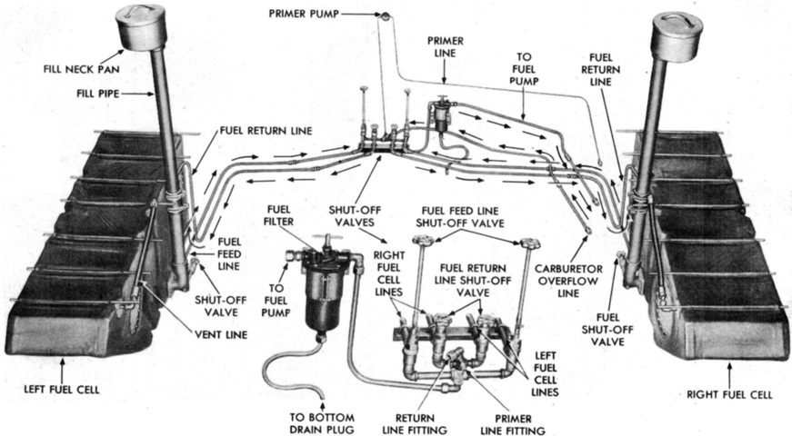
A self-sealing molded rubber fuel tank was installed in each pontoon next to manhole covers 5 and 6. Late-production vehicles featured a second fuel tank in the right pontoon. (Picture from TM 9-776 Landing Vehicle, Tracked, Mk.IV LVT(4).)
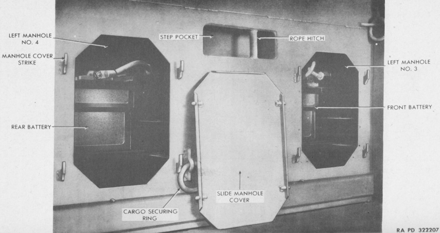
Two 6-volt, 320 amp-hour storage batteries were connected in series in the left pontoon to maintain a 12-volt electrical system. The batteries were manufactured according to requirements set out by the US Navy rather than the Army's Ordnance Corps, with a different specific gravity being specified. Tracked landing vehicle batteries had a specific gravity of 1.200-1.225 at 80°F (27°C) when fully charged, versus 1.275 to 1.300 for batteries conforming to Ordnance Corps standards. (Picture from TM 9-776 Landing Vehicle, Tracked, Mk.IV LVT(4).)
The transmission, controlled differential, and final drives are shown dismounted. First and reverse speeds in the transmission were sliding gears. (Picture from TM 9-776 Landing Vehicle, Tracked, Mk.IV LVT(4).)
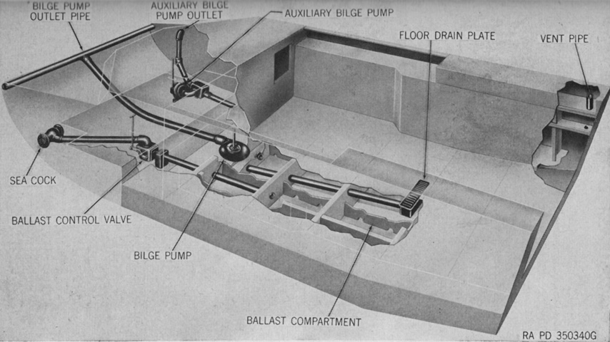
A schematic of a late-production ballast and bilge system is sketched here. The bilge pump, powered by a power takeoff from the engine, was a Peerless Pump Division V156DL with a capacity of 500gal/min (1,900L/min) at 2,400 engine rpm. A ballast control valve was installed in order to bring water into the ballast compartment so that the vehicle would float sufficiently low when no cargo was aboard. On early vehicles this valve was operated by a pull handle on the left rear sponson box ahead of the ramp winch. Later models, as shown in this image, utilized a two-way flap valve controlled from the driver's seat. When the handle was pulled upwards, water ingested from the sea cock flowed into the ballast compartment. When the handle was pushed down, the water in the ballast compartment passed into the bilge sump to be automatically pumped overboard. In order to leave water in the ballast compartment, the handle was pulled up and the sea cock closed. (Picture from TM 9-775 Tracked Landing Vehicle Mk 4 (LVT(4)) Tracked Landing Vehicles (Armored) Mk 4 (LVT(A)(4)) and Mk 5 (LVT(A)(5)).)
The early armored cab is shown here, with the observation hatch in front of the driver and the periscopes in the drivers' roof hatches protected by plastic hemispheres. (Picture from ORD 7-8-9 SNL G-209 Service Parts Catalog for Vehicle, Landing, Tracked, Mk. IV, LVT (4).)
A tractor with applique armor is seen from above. (Picture from TM 9-775 Tracked Landing Vehicle Mk 4 (LVT(4)) Tracked Landing Vehicles (Armored) Mk 4 (LVT(A)(4)) and Mk 5 (LVT(A)(5)).)
The early armored cab could also be found with the bow machine gun mount. (Picture from TM 9-775 Tracked Landing Vehicle Mk 4 (LVT(4)) Tracked Landing Vehicles (Armored) Mk 4 (LVT(A)(4)) and Mk 5 (LVT(A)(5)).)
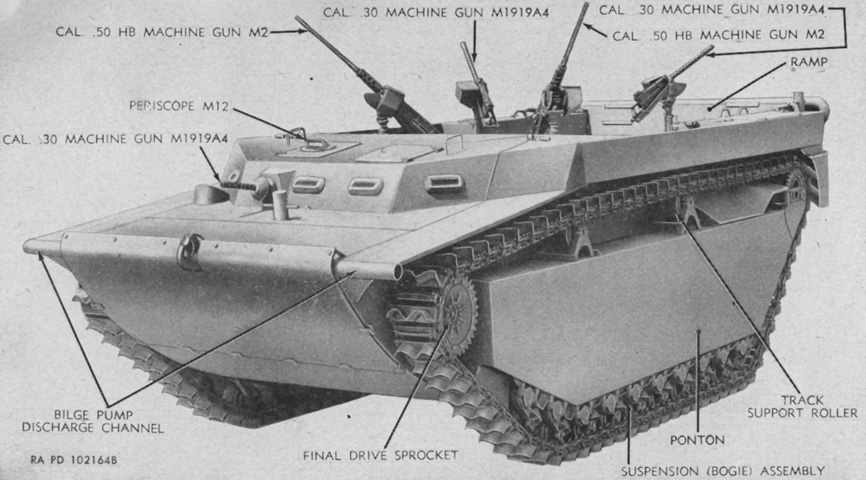
This vehicle has the late armored cab, and all five machine guns are mounted. (Picture from TM 9-775 Tracked Landing Vehicle Mk 4 (LVT(4)) Tracked Landing Vehicles (Armored) Mk 4 (LVT(A)(4)) and Mk 5 (LVT(A)(5).)
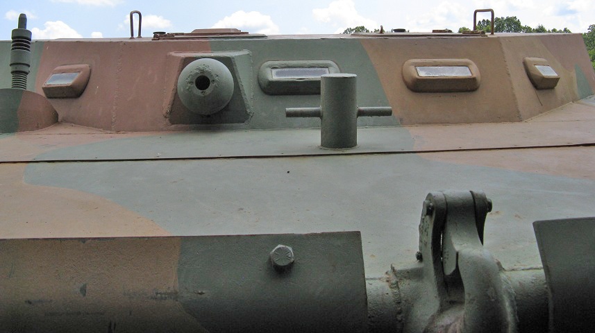
This vehicle is fitted with the final version of the armored cab. The driver and assistant driver are provided with vision blocks, and the bow machine gun mount is in front of the assistant driver. Note that the assistant driver's overhead hatch has a periscope, while the driver's does not.
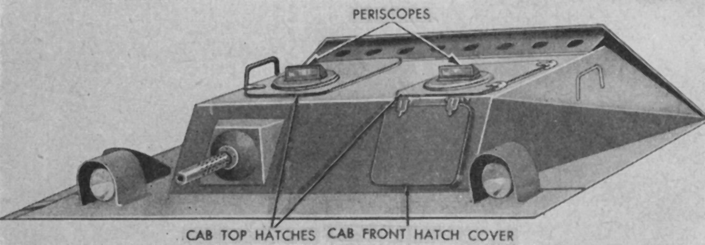
Further details of the late armored cab are seen in this image. (Picture from TM 9-775 Tracked Landing Vehicle Mk 4 (LVT(4)) Tracked Landing Vehicles (Armored) Mk 4 (LVT(A)(4)) and Mk 5 (LVT(A)(5)).)
The applique armor bolted to the front of this LVT4 can be seen. Note the cutout to accommodate the bow towing pintle. The bumper (damaged on this vehicle) also doubled as a bilge pump drainage channel.
Also visible in the previous image is the hull escape hatch located to the driver's left, level with the floor. It allowed egress through the pontoon. (Picture from TM 9-775 Tracked Landing Vehicle Mk 4 (LVT(4)) Tracked Landing Vehicles (Armored) Mk 4 (LVT(A)(4)) and Mk 5 (LVT(A)(5)).)
Early vehicles featured the above machine gun mounts in the passenger compartment. Two fixed machine gun mounts (shown on the left) were attached to the cab rear, and a pivot machine gun mount (shown on the right) was installed near the middle of each side of the compartment. (Picture from Weapon Mounts for Secondary Armament.)
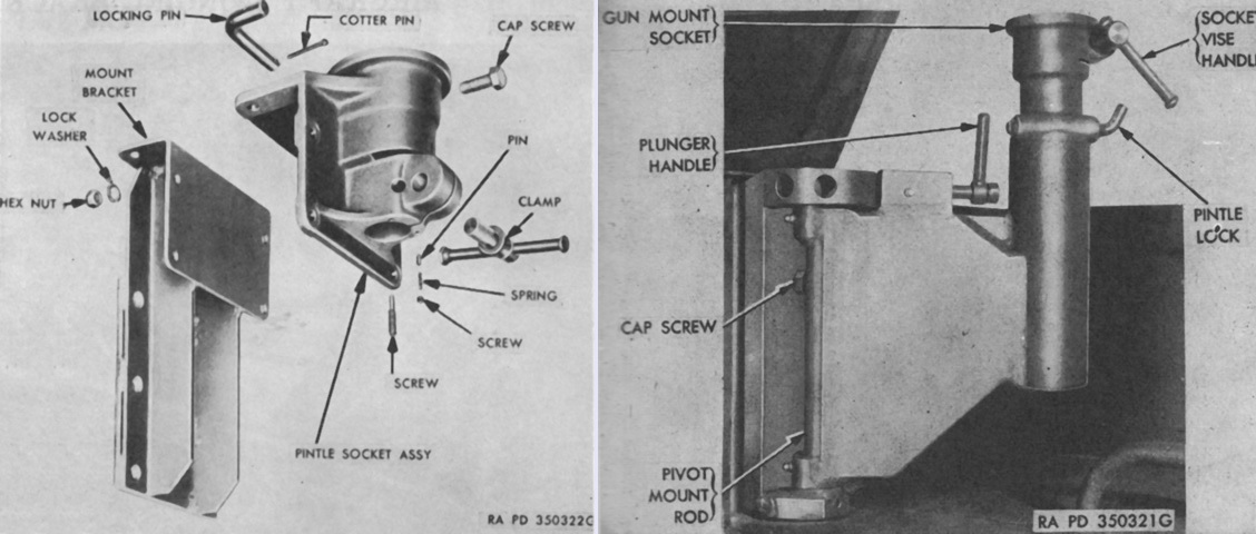
Later machines had fixed (left) and pivot (right) mounts that could accept standard pintles. (Picture from Weapon Mounts for Secondary Armament.)
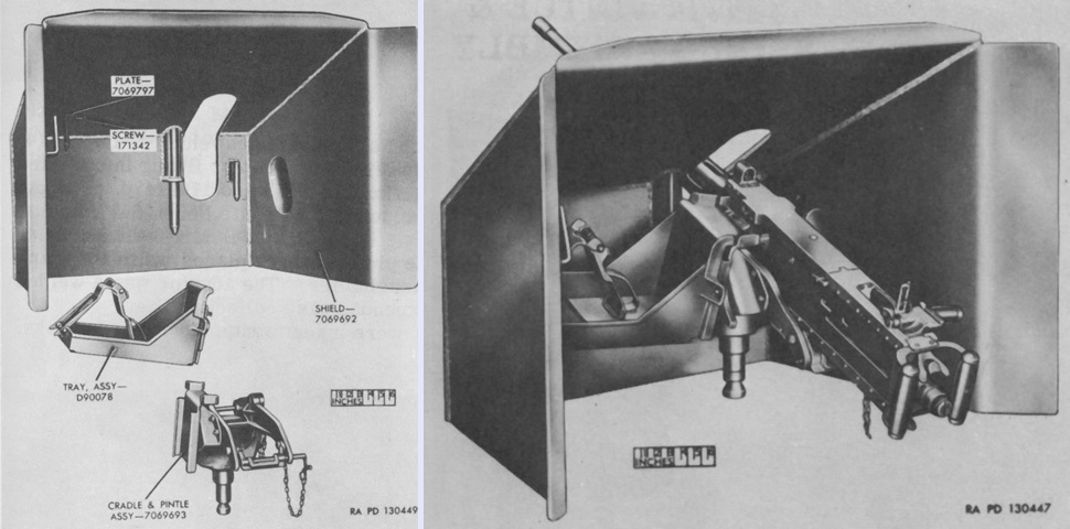
In addition to the cab and applique armor, shields for the machine gunners could be installed. On the left, the separate components of the shielded bracket mount 7069694 or M69E are shown, while the assembly is complete with the machine gun on the right. (Picture from Weapon Mounts for Secondary Armament.)
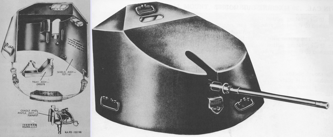
The shield in the later shielded bracket mount M69 or M69D featured a vision block and a depression limit stop. The mount M70 for the .30cal machine guns was also an option. (Picture from Weapon Mounts for Secondary Armament.)
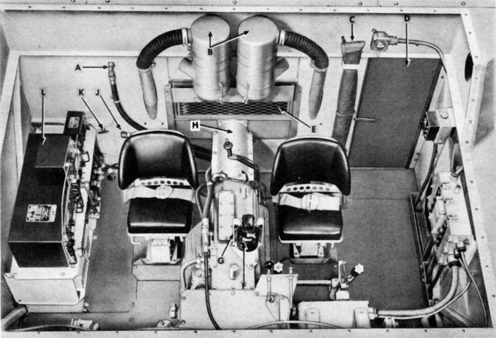
The layout of the drivers' cab compartment is revealed with the cover removed. A. Transmission oil outlet line to cooler. B. Air cleaner. C. Spare antennae. D. Escape door. E. Ventilating screen. F. Compass. G. Non-magnetic screwdriver. H. Propeller shaft guard. J. Transmission oil inlet line. K. Fixed fire extinguisher release handle. L. Radio. (Picture from TM 9-776 Landing Vehicle, Tracked, Mk.IV LVT(4).)
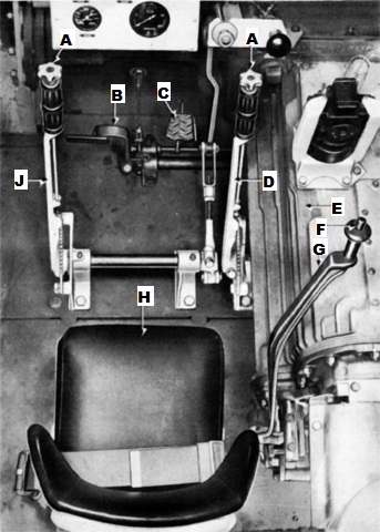
The driver's controls are shown here. The steering levers had a ratcheting locking mechanism that enabled the driver to keep the levers in position when the vehicle was parked, and the gearshift lever had a latch to prevent accidental shifting into first or reverse gears. The early style of compass is visible to the right of the right steering lever. A. Ratchet handle. B. Clutch pedal. C. Accelerator pedal. D. Right steering lever. E. Transmission. F. Latch button. G. Gearshift lever. H. Driver's seat. J. Left steering lever. (Picture from TM 9-776 Landing Vehicle, Tracked, Mk.IV LVT(4).)
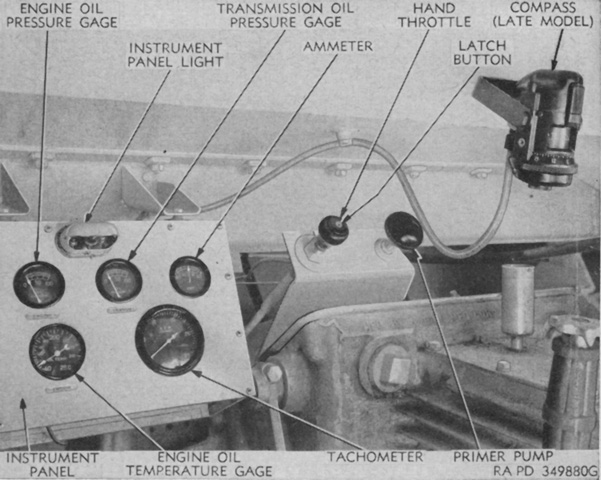
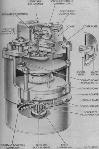
The right side of the driver's position is illustrated here, and the right steering lever can be seen in the lower left corner. The compass is the Sherill Research Corporation ORD M6, found in later-production vehicles. (Picture from TM 9-775 Tracked Landing Vehicle Mk 4 (LVT(4)) Tracked Landing Vehicles (Armored) Mk 4 (LVT(A)(4)) and Mk 5 (LVT(A)(5)).)
Before the Sherill compass was used, early machines were equipped with the Pioneer Instrument Company's No. 1829 mounted on the transmission to the driver's right. (Picture from TM 9-775 Tracked Landing Vehicle Mk 4 (LVT(4)) Tracked Landing Vehicles (Armored) Mk 4 (LVT(A)(4)) and Mk 5 (LVT(A)(5)).)
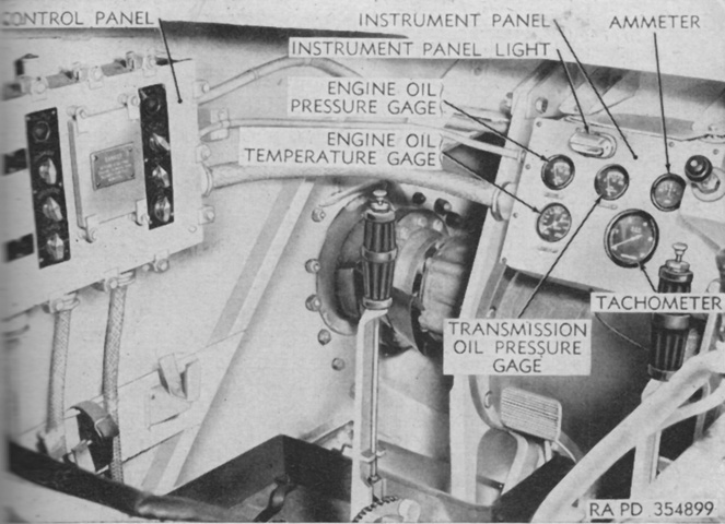
To the driver's left was his control panel. In front can be seen the left-side final drive exiting to the drive sprocket. (Picture from TM 9-775 Tracked Landing Vehicle Mk 4 (LVT(4)) Tracked Landing Vehicles (Armored) Mk 4 (LVT(A)(4)) and Mk 5 (LVT(A)(5)).)
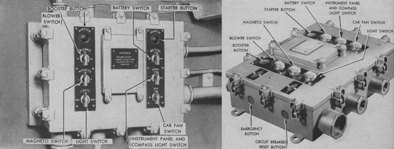
Early and late versions of the driver's control panel are shown here. The early type did not have the emergency and circuit breaker reset buttons. The booster button connected the booster coil to the right magneto to provide additional high tension current when the engine was started. The blower switch activated or turned off the blower in the engine room in order to diffuse fumes. This switch was a safety and needed to be on before the starter and booster buttons could be used. The light switch in the lower left corner was for the exterior lights, but service lights were eliminated from late-production machines. The emergency button on late control panels could override the blower switch safety in case of failure and allow the starter and booster buttons to activate. (Picture from TM 9-775 Tracked Landing Vehicle Mk 4 (LVT(4)) Tracked Landing Vehicles (Armored) Mk 4 (LVT(A)(4)) and Mk 5 (LVT(A)(5)).)
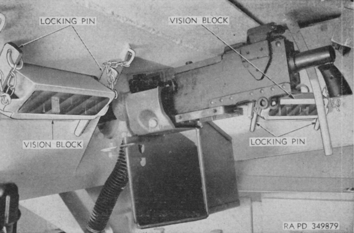
The assistant driver's position in the late-model armored cab is shown here. As usual, no sighting device was provided for his machine gun, which was aimed via correcting tracers and impacts. (Picture from TM 9-775 Tracked Landing Vehicle Mk 4 (LVT(4)) Tracked Landing Vehicles (Armored) Mk 4 (LVT(A)(4)) and Mk 5 (LVT(A)(5)).)
The caliber .30 ball mount 7722940 was similar to the ball mount D59830 that could be found in the light tank M5, but used different studs on the case collection bag supports, a different chain on the gun locking pin, and the equilibrator spring was mounted to the hull instead of being suspended from the ball mount assembly. (Picture from Weapon Mounts for Secondary Armament.)
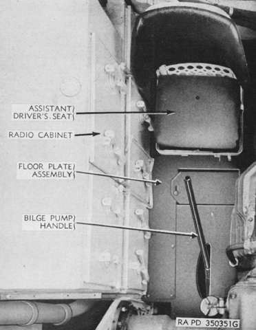
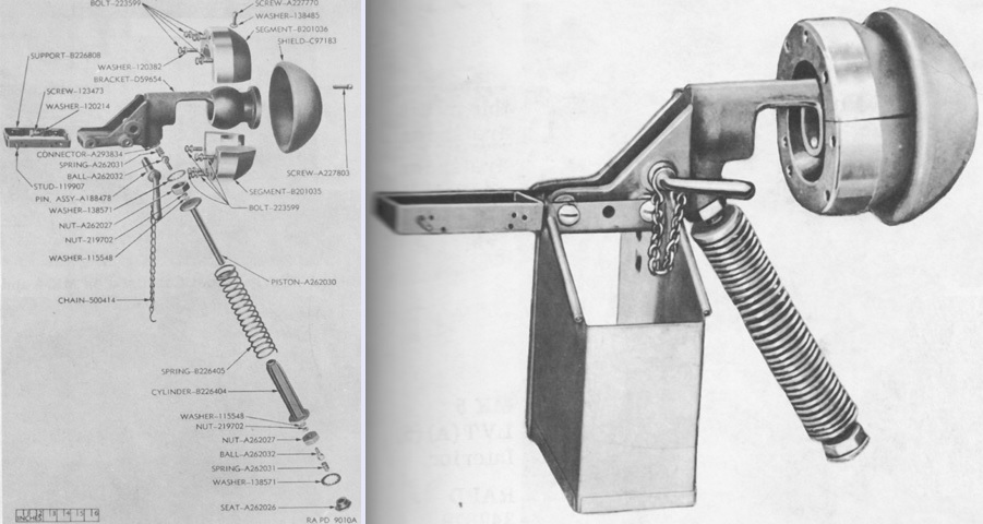
Some late-production tractors were fitted with an auxiliary bilge pump at the assistant driver's position. This was manually operated by moving the handle back and forth, and was to be used during emergencies, when the main bilge pump was inoperative, or when there was excessive leakage or the main bilge pump could not handle the water load (although, in the last two instances, one wonders how much hope could be pinned on the assistant driver to salvage a situation for which the engine-powered main bilge pump was insufficient...). (Picture from TM 9-775 Tracked Landing Vehicle Mk 4 (LVT(4)) Tracked Landing Vehicles (Armored) Mk 4 (LVT(A)(4)) and Mk 5 (LVT(A)(5)).)
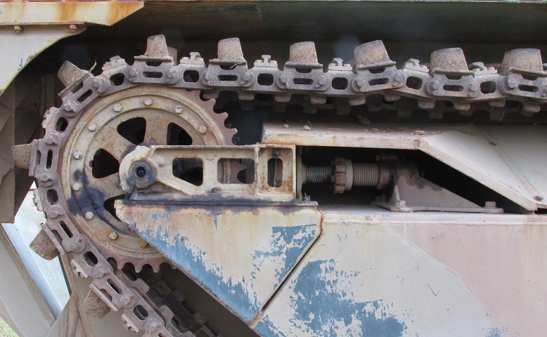
This shot details the rear idler sprocket and the track tensioning mechanism. It was necessary to remove the mud guard above the adjusting screw to adjust the track tension. Correct tension was achieved when any gap between the idler slide and the slide head cap at the end of the screw was closed. Once the gap disappeared, the screw was turned three more notches then clamped securely.
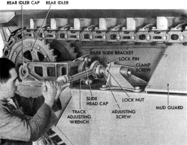
The track tension is being adjusted here, showing the slide head cap and idler slide. (Picture from TM 9-776 Landing Vehicle, Tracked, Mk.IV LVT(4).)
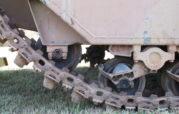
In contrast to the LVT2, the rear road wheel on the LVT4 was fixed to the pontoon.
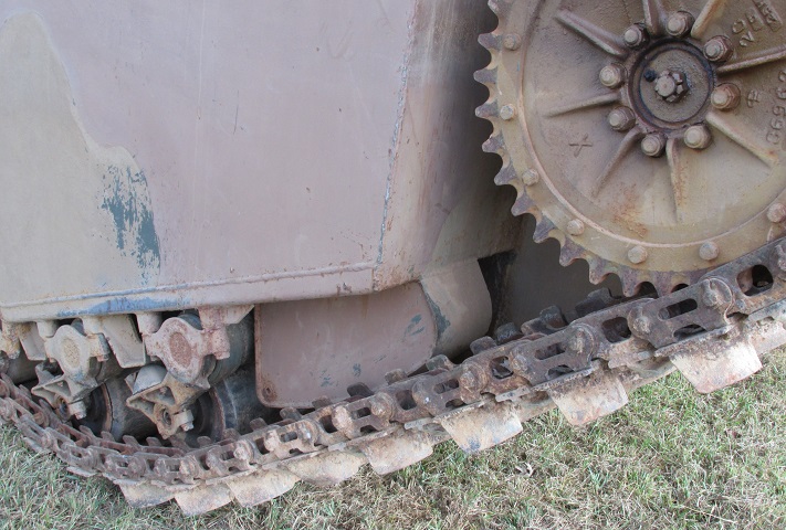
Details of the front drive sprocket, track skid on the front of the pontoon, and road wheel attachments can be seen here.
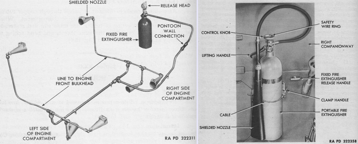
The fixed fire extinguisher system (left) consisted of a 10lb (4.5kg) CO2 cylinder found in the pontoon on the right side of the engine compartment, and it was routed to six nozzles in the engine compartment as diagrammed here. Two remote activation handles were provided: one behind the driver's seat on the bulkhead, and the second on the inner pontoon wall in the right companionway just ahead of the right front lifting eye. It was preferable for the tractor engine to be off if the extinguisher was used, but it could still smother a fire with the engine turning at 1,200rpm. The cylinder weighed 34.5lb (15.6kg) empty.
In addition, a portable 15lb (6.8kg) CO2 extinguisher (right) was stowed in the pontoon in the right companionway. The location of the second remote activation handle for the fixed extinguisher is visible in this image. Without the hose and discharge horn, the cylinder weighed 36.25lb (16.44kg) empty. (Picture from TM 9-776 Landing Vehicle, Tracked, Mk.IV LVT(4).)
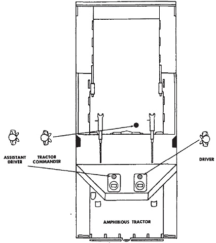
The positions of the crew are shown in this diagram. Thirty passengers could be carried in the rear compartment. (Picture from FM 17-34 Amphibious Tank and Tractor Battalions.)
