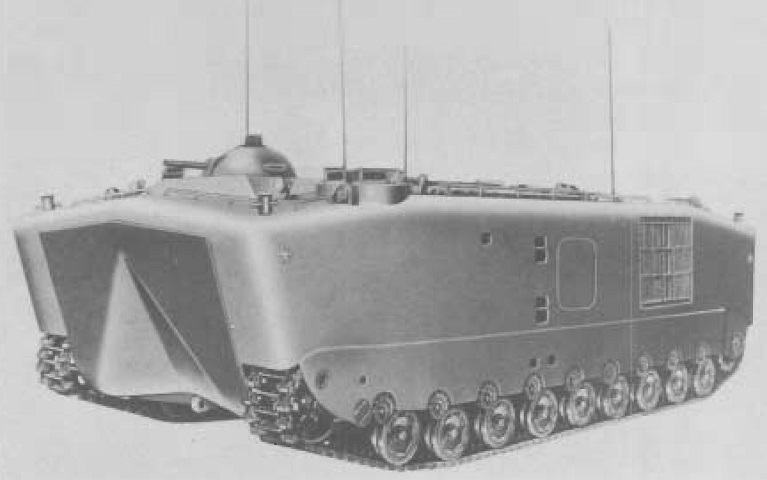
Landing Vehicle, Tracked, Personnel, Mark 5.
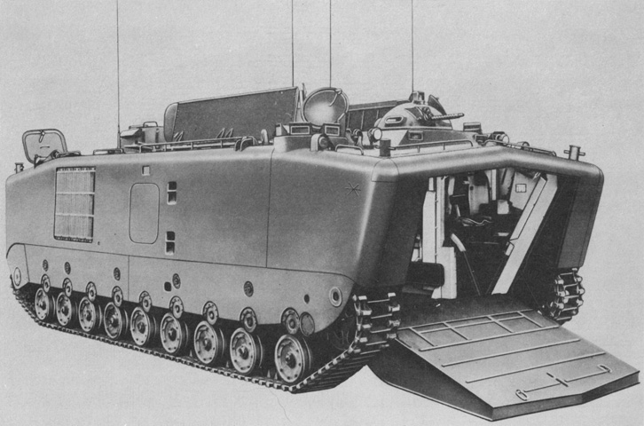
The design of the LVTP5, with its inverted-vee shaped hull and low-slung, internal track channel, was a sharp break from earlier amphibian tractors. The large bow ramp is obvious in the front of the vehicle, and the machine gun could be mounted in a cupola as shown here. The mesh grille near the rear of the vehicle was for the port radiator; an escape hatch is to the front of this screen, and boarding steps are just in front of the escape hatch. In front of and just above the upper step is a recess for the fire extinguisher activation handle. The new track design lacking conspicuous external paddles is also apparent. (Picture from Research, Investigation and Experimentation in the Field of Amphibian Vehicles.)
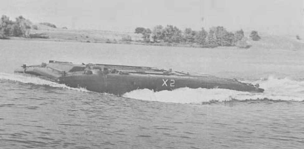
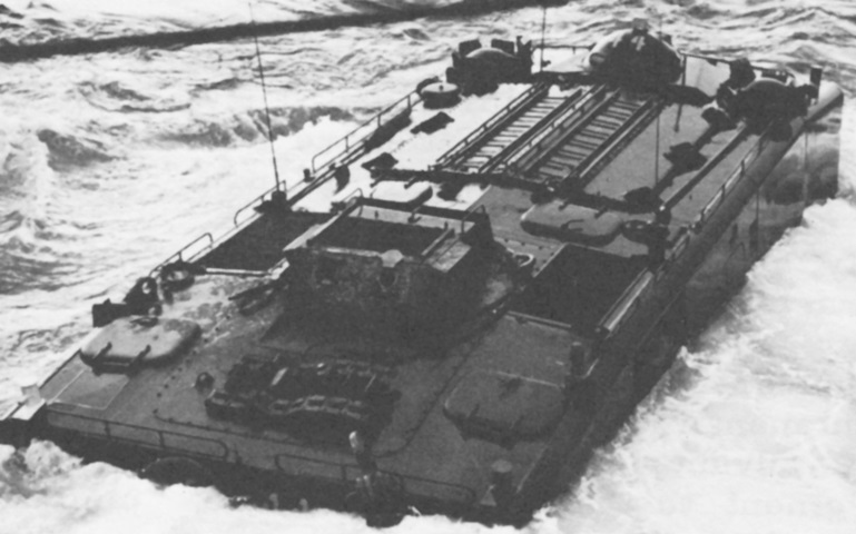
The freeboard of a waterborne LVTP5 is illustrated here. Note the machine gun cupola is not mounted. (Picture from Research, Investigation and Experimentation in the Field of Amphibian Vehicles.)
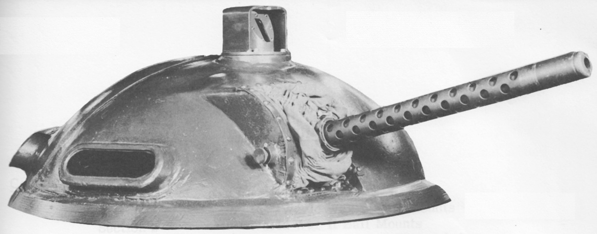
The G-1 machine gun cupola is seen here. It was constructed from ⅜" (.953cm) constant thickness homogeneous armor that was sloped to a ballistic equivalent of ⅝" (1.59cm) thickness. Excluding the sight, it was 12¼" (31.11cm) tall, was 36⅝" (93.028cm) in diameter, and weighed 442lb (200kg) including the gun and a 250-round ammunition box. It mounted to a standard 29.75" (75.57cm) deck opening. (Picture from Weapon Mounts for Secondary Armament.)
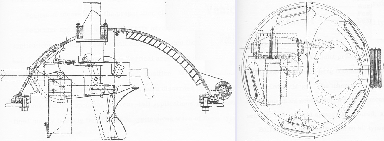
Two cross-sectional views of the machine gun cupola are sketched. (Picture from Weapon Mounts for Secondary Armament.)
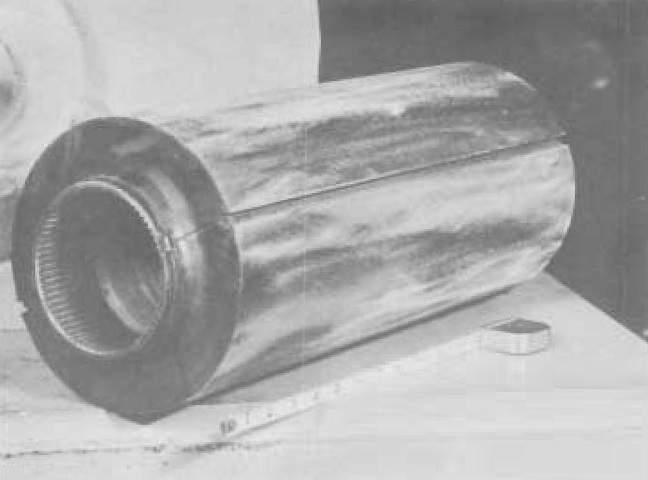
A torsilastic spring assembly is shown in this image. The tubular rubber spring is bonded between an inner tube that connects securely to the hull and a split outer tube onto which is pressed the road wheel arm. (Picture from Research, Investigation and Experimentation in the Field of Amphibian Vehicles.)
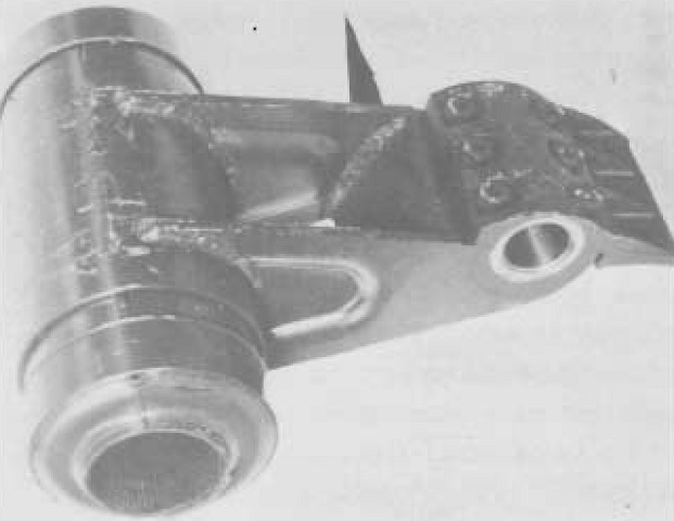
This is a completed suspension arm assembly, and the open inner metal tube can be seen to the left of the image. End caps were placed over the exposed ends of the split outer tube before installation onto the vehicle. The road wheel would be mounted in the smaller hole to the right. Lubrication was unnecessary for (and indeed oil could be harmful to) the rubber spring. (Picture from Research, Investigation and Experimentation in the Field of Amphibian Vehicles.)
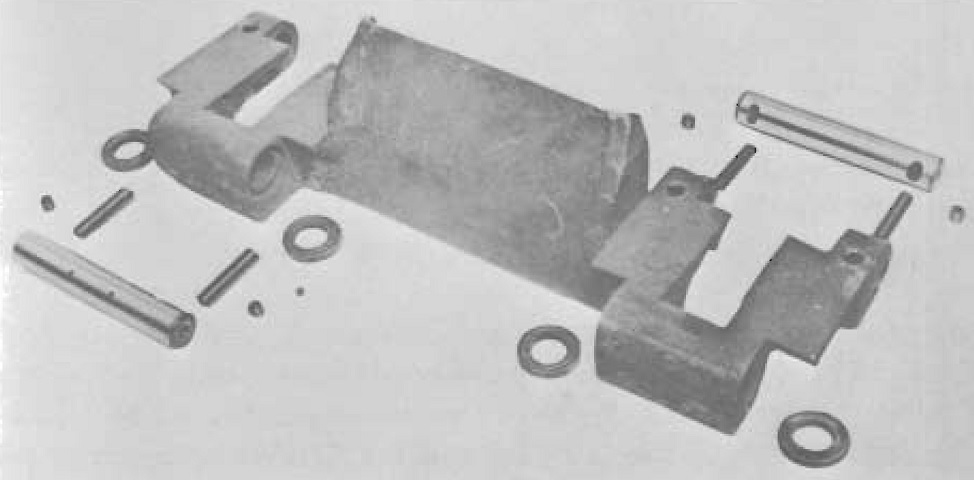
Details of a track shoe can be gleaned here. Modifications during production included changes to the track pins. Initially, the hollow pins had been filled with lubricant during production and the two small holes in the pins distributed the lubricant to the pin bore. A self-lubricating bushing was subsequently introduced to prevent scoring of the pins and bores, and consequently the hollow pins were eliminated and the cavity around the seals was also packed with lubricant. (Picture from Research, Investigation and Experimentation in the Field of Amphibian Vehicles.)
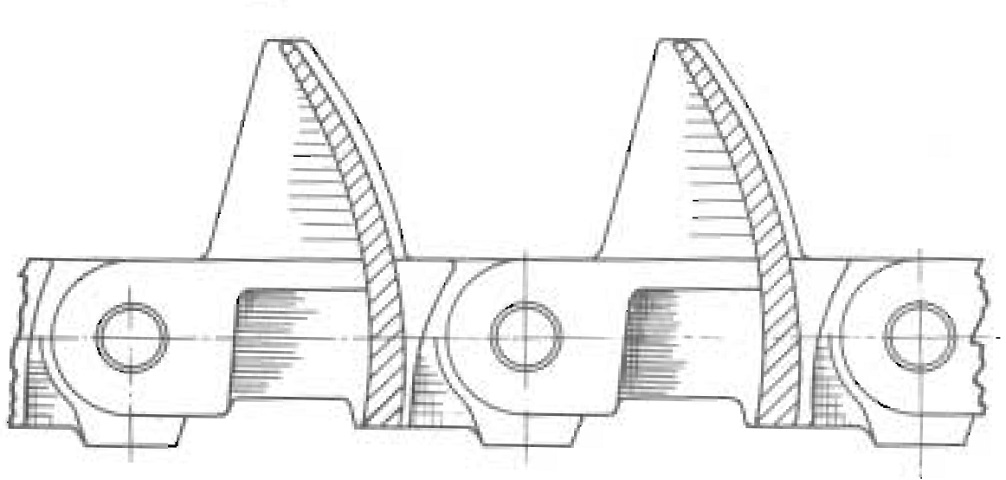
The profile of the grouser, which provides propulsion in the water and also acts as the track center guide, is shown in this image. (Picture from Research, Investigation and Experimentation in the Field of Amphibian Vehicles.)
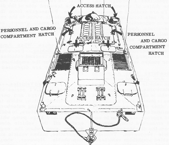
The rooftop hatches accessing the crew positions and the cargo/personnel compartment are labeled in this sketch. (Picture from FMFM 9-2 Amphibian Vehicles.)
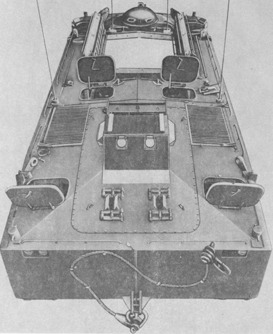
The hull roof hatches are open here, showing the folding nature of the personnel and cargo compartment hatch. (Picture from SL-4-00348A and SL-4-00511A.)
The bow ramp has been lowered, providing a glimpse of the driver's position at the left front corner of the hull. (Picture from SL-4-00348A and SL-4-00511A.)
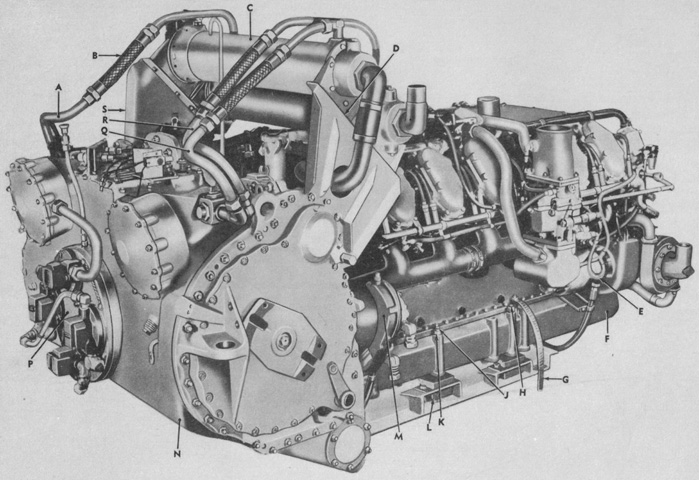
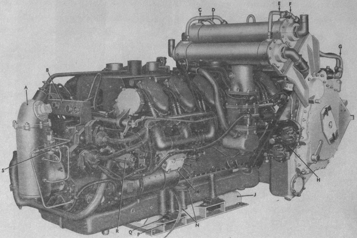
The combined engine and transmission are displayed from the left rear. Unlike the AV-1790 versions found in tanks, the LV-1790 was liquid-cooled. When running on land, the radiators on each side of the engine compartment were cooled by fans, but when operating in water the driver turned the fans off and the radiators were cooled by the submersion of the radiator compartments. A. Tube assembly. B. Hose assembly. C. Cooler. D. Support. E. Cable assembly. F. Engine. [G. Unlabeled.] H. Stud. J. Stud. K. Nut. L. Mount. M. Cover. N. Transmission. P. Cover assembly. Q. Tube assembly. R. Tube assembly. S. Support. (Picture from SL-4-00348A and SL-4-00511A.)
The engine is shown from the opposite angle. A. Transmission. B. Panel assembly. C. Tube assembly. D. Tube assembly. E. Tube assembly. F. Tube assembly. G. Tube assembly. H. Cover. J. Frame. K. Cover. L. Box assembly suppressor. M. Clamp. N. Lead. P. Screw. Q. Nut. R. Unit. S. Valve. (Picture from SL-4-00348A and SL-4-00511A.)
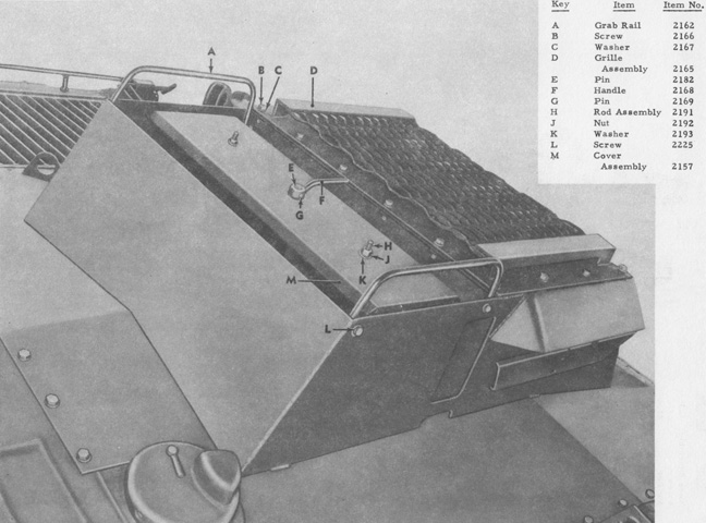
The superstructure introduced with the -A1 modifications is detailed in this image. (Picture from SL-4-00348A and SL-4-00511A.)
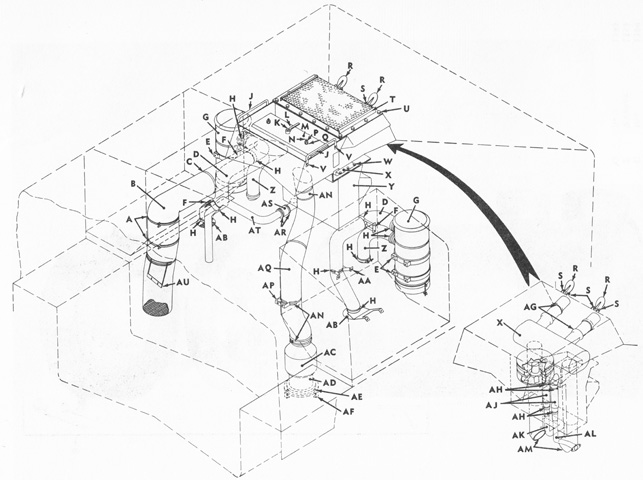
The modified engine aspiration and exhaust is diagrammed in this drawing. The engine air cleaners are letter G, and the muffler is X. (Picture from SL-4-00348A and SL-4-00511A.)
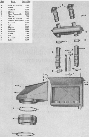
The engine exhaust piping and muffler are isolated from the superstructure and disassembled. (Picture from SL-4-00348A and SL-4-00511A.)
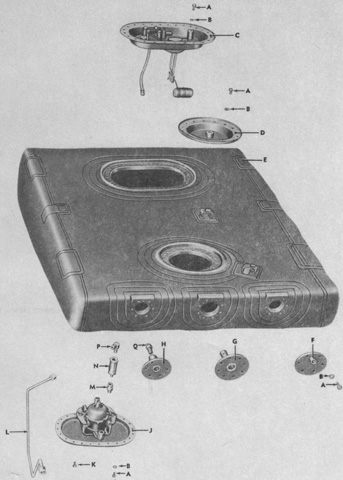
An exploded view of the fuel tank assembly is presented here. A. Screw. B. Washer. C. Cover assembly. D. Cover. E. Tank. F. Plate assembly. G. Valve. H. Plate assembly. J. Mounting assembly. K. Plug. L. Bent tube. M. Reducer. N. Valve. P. Elbow. Q. Adapter. (Picture from SL-4-00348A and SL-4-00511A.)
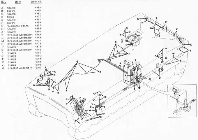
An electrical diagram is drawn above. The batteries were housed at the right rear corner of the hull. (Picture from SL-4-00348A and SL-4-00511A.)
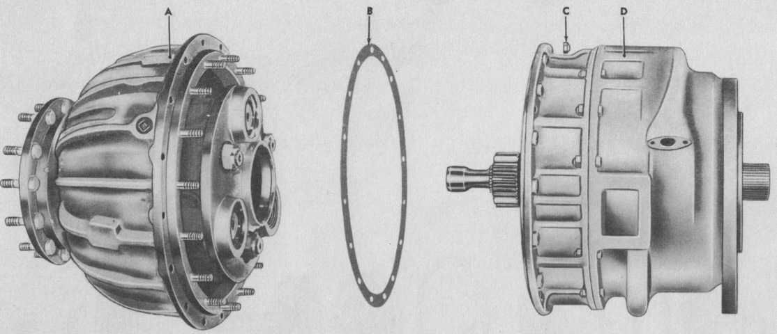
A final drive assembly is exploded in this picture. A. Carrier assembly. B. Gasket. C. Nut. D. Clutch assembly. (Picture from SL-4-00348A and SL-4-00511A.)
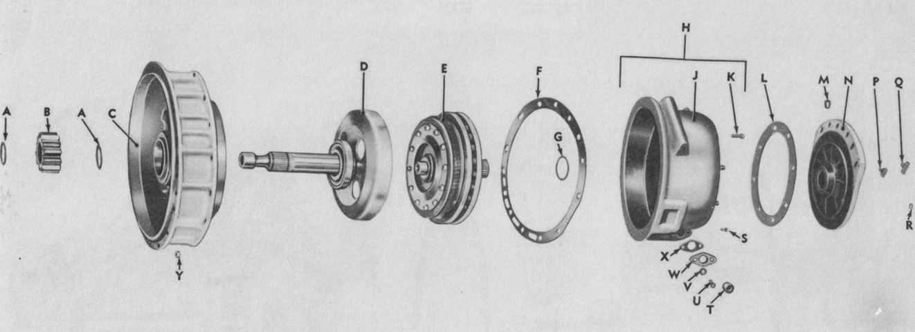
Components in the final drive clutch and housing assembly are detailed. A. Ring. B. Gear. C. Housing assembly. D. Shaft assembly. E. Clutch assembly. F. Gasket. G. Washer. H. Housing assembly. J. Housing. K. Bolt. L. Gasket. M. Plug. N. Adapter. P. Strainer. Q. Strainer. R. Nut. S. Bolt. T. Plug. U. Bolt. V. Washer. W. Flange. X. Gasket. Y. Nut. (Picture from SL-4-00348A and SL-4-00511A.)
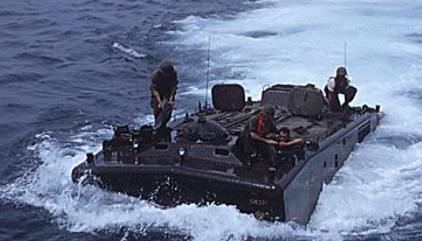
This view of a waterborne LVTP5A1 showcases its roof features. The large engine air intake and exhaust superstructure is visible on the vehicle's rear next to the kneeling marine. The driver is in his cupola on the vehicle's front left corner, and the commander's cupola is on the opposite side. The machine gun cupola or turret is placed between them. There are two open entrance hatches near the hull's center, and a set of access hatches remain closed closer to the rear corners of the hull. The aperture in the vehicle's side closest to the front is the fire extinguisher pull handle. A larger boarding step is behind this, and towards the rear the port radiator compartment is covered by a large mesh screen. Cylindrical mooring bitts are placed on the extreme corners of the roof. (Picture taken 19 Apr 1968; available from the National Archives.)
The vehicle is seen from the rear in this picture. Boarding ladders were stowed on the cargo hatch covers; these allowed ingress into and egress from the vehicle via the cargo hatch. (Picture from FMFM 9-2 Amphibian Vehicles.)
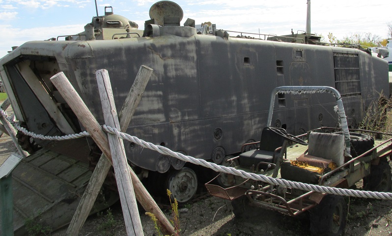
The large housing on the rear hull roof indicates this this machine has undergone the -A1 modifications. A lifting eye is visible behind the driver's station, and a bilge outlet is visible behind the lifting eye.
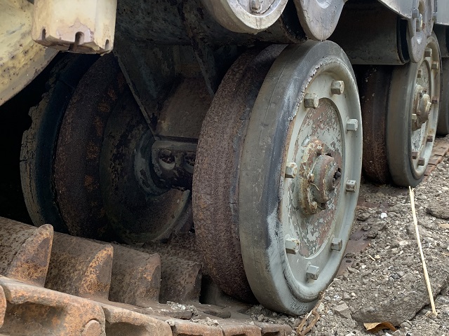
The paired road wheels on each side of the axle are visible here. The outer wheels were clad with a rubber tire, while the inner steel wheels helped absorb shock loads.
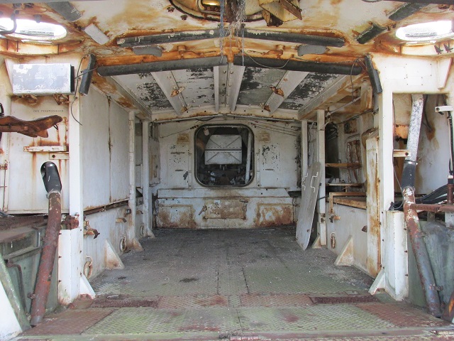
This vehicle's cavernous interior is shown here. The commander occupied the seat in the front left of the image, with the driver on the vehicle's left side to the right of the image. Bilge pump piping makes its way to the roof from under both of their stations. The machine gun cupola is visible at the top with wiring hanging from it. At the rear of the passenger compartment, the large engine compartment access hatch is dismounted and resting to the right. A pioneer tool rack is directly below the engine compartment access, and battery compartments flank the tool rack. Cargo lashing rings are attached to the hull sides near the floor. A shelf for radio sets was provided behind the driver.
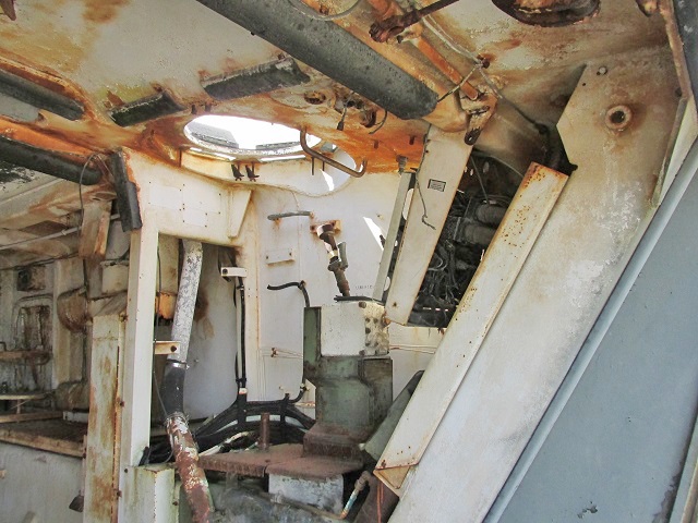
The commander's adjustable seat bottom is at the center of this picture, and behind is stowage for a pyrotechnics box.
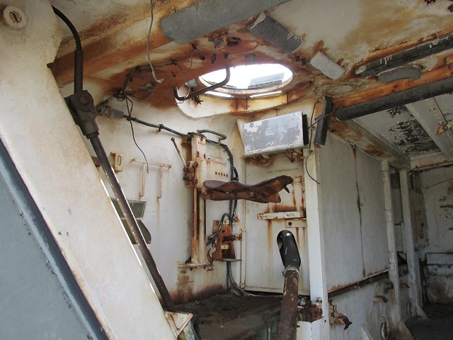
The driver's seat is missing, but his steer and shift control lever can be seen atop the white control box. The mount for his seat's vertical adjustment slide is just below and in front of the grab handle on the side of the hull. The mounting bracket lower and farther to the rear was for the radio control box, the wiring for which can be seen hanging from the side wall. The post rising from the floor inboard of where the driver's seat would be shows where the ramp control lever would be mounted. The side of the large accelerator pedal can be seen above the hose coupling near the front, and a brake pedal would be outboard of the accelerator. The driver's instrument panel is above the pedals.
The cupola was surrounded by vision blocks, and another is seen in front of the cupola on each side. The elevation arm can be seen with its pistol grip trigger, and the ammunition box bracket is still attached to its left side. The receptacle for the rotating azimuth control handle is on the far side of the cupola.
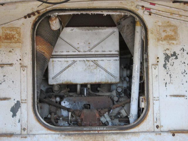
The open engine access panel is shown here. The white pipe from the fuel filler on the roof is at the right of the image, and air ducting can be seen descending from both sides of the roof behind. Drive shafts for the engine fans rise from the engine at the bottom front to the upper sides of the hull.
