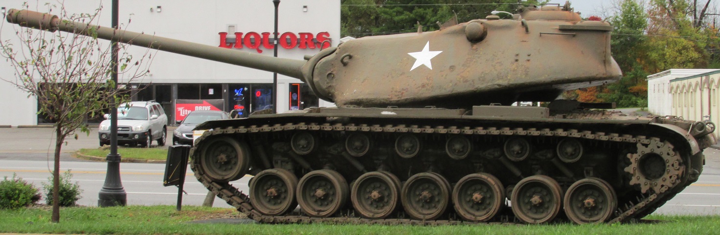
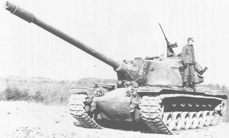
120mm Gun Tank M103 in Radcliff, Kentucky.
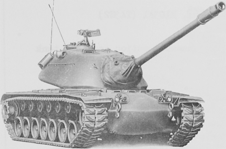
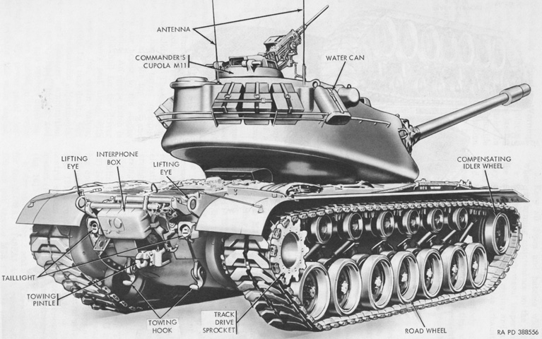
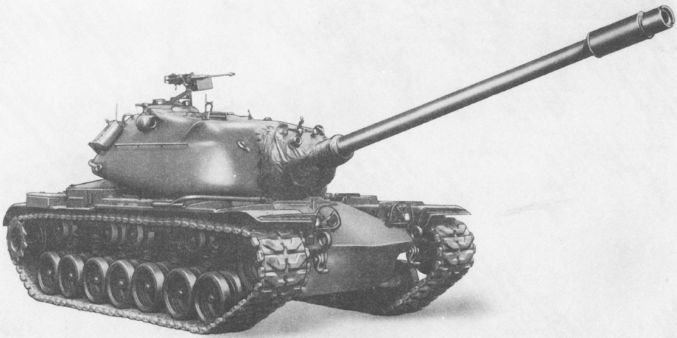
Perhaps the most striking feature of the M103 heavy tank was its massive turret, in which the commander and gunner sat far to the rear. The bore evacuator on the 120mm gun is visible near the muzzle. Details of the running gear are revealed here, including the five shock absorbers. A handrail was welded to the turret side below the ventilating blower.
The commander's machine gun and the dust cover for the gun mount are present on this machine. The vane sight 6582199 that assisted the commander in aiming can be seen in front of his machine gun. (Picture from TM 9-2350-206-12.)
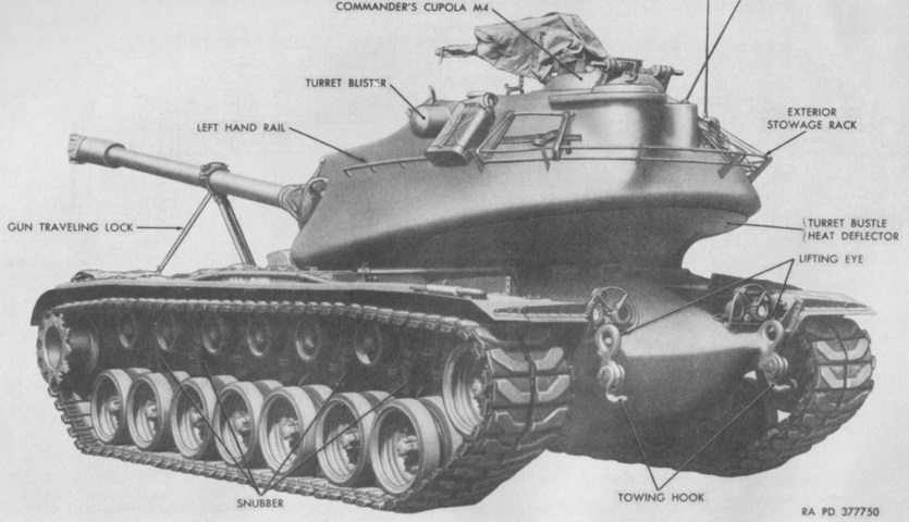
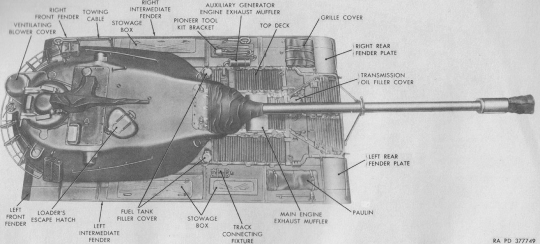
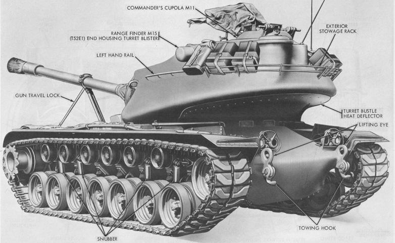
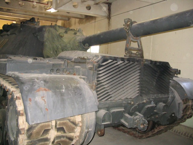
The turret is reversed, and the main gun is secured in its travel lock on the rear hull. The long turret bustle overhanging the main engine exhaust necessitated mounting a heat deflector on the bottom of the rear turret. (Picture from TM 9-2350-206-12.)
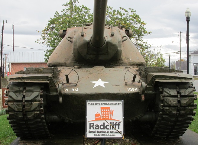
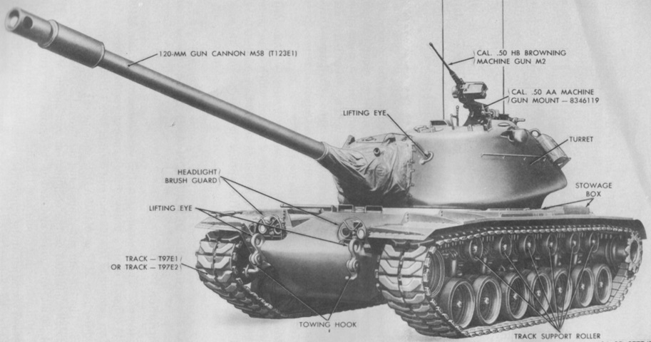
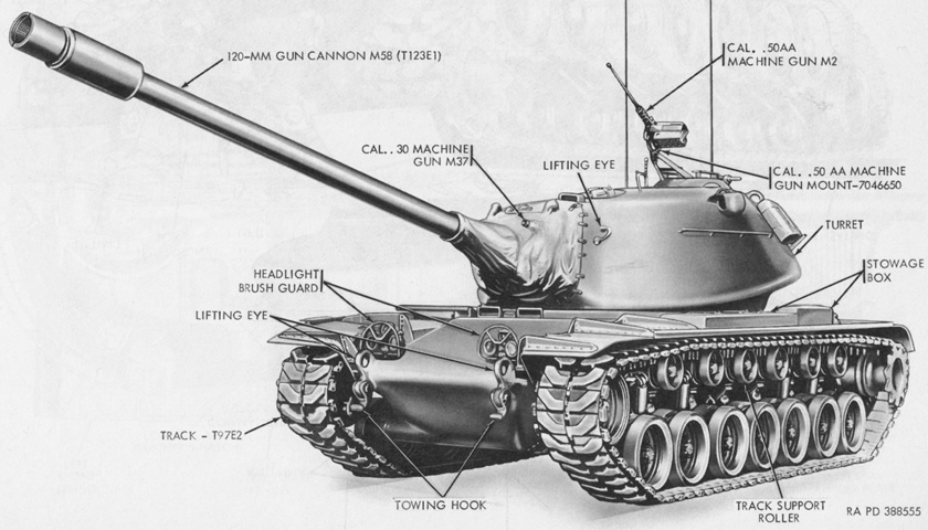
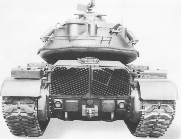
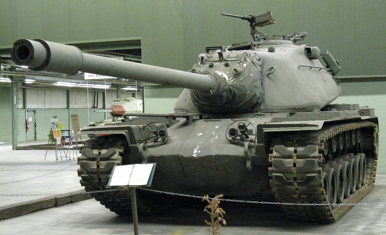
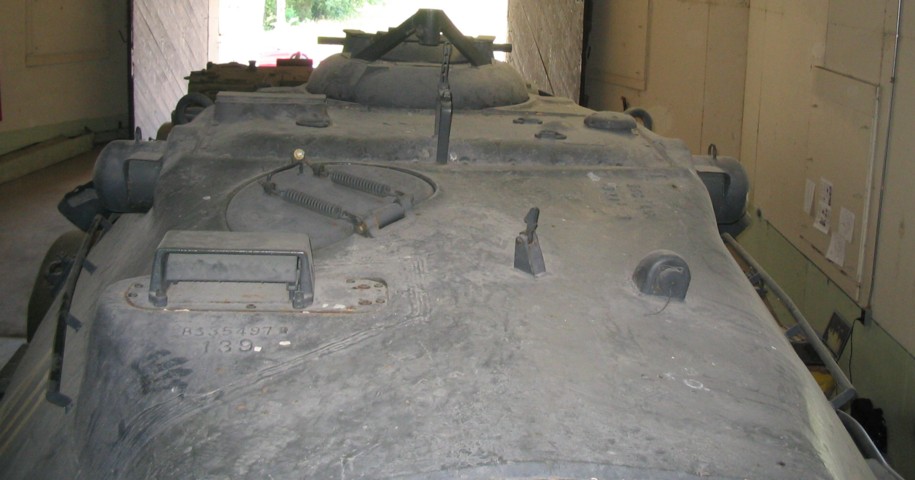
This front view showcases the cast elliptical hull similar to that found on the 90mm gun tank M48. Round headlight brush guards are present, although the lights themselves are absent. The apertures for the coaxial machine guns are visible on each side of the main gun, and the armored blisters for the M14 rangefinder can be seen on each side of the turret. Lifting and towing eyes are on the extreme front of the hull.
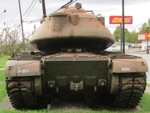
A towing pintle is centered on the bottom of the hull rear plate, with towing eyes on each side at the extreme bottom. Lifting eyes are just inboard of the fenders at the top of the rear plate. Normally there would be attachments for the gun travel lock and an infantry interphone box in between the lifting eyes, but these are absent. Transmission access was granted by the plates surrounding the towing pintle as well as the grille doors on the rear deck visible sloping downwards towards the camera. Taillights/brakelights are just inboard of the final drive housings. The large bulge in the turret rear is for the ventilating blower housing, and two smaller antenna mounts were welded to the turret rear and right-rear.
The stowed travel lock and infantry interphone are present in this image. (Picture from TM 9-2350-206-12.)
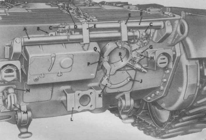
A closer look at the travel lock and hull rear is given here. A. Gun traveling lock--left support. B. Gun traveling lock--front support. C. Gun traveling lock--support pin. D. Gun traveling lock--front support bracket. E. Gun traveling lock--support stowage bracket. F. Gun traveling lock--right support. G. Gun traveling lock--right lock stowage bracket. H. Gun traveling lock--stowage bracket pin. J. Gun traveling lock--locking handle hook. K. Gun traveling lock--locking handle. L. Towing pintle mounting bracket. M. Towing pintle. N. Towing pintle stowage bracket. P. Gun traveling lock--latch hook. Q. Gun traveling lock--left lock stowage bracket. R. Gun traveling lock--lock. (Picture from TM 9-2350-206-12.)
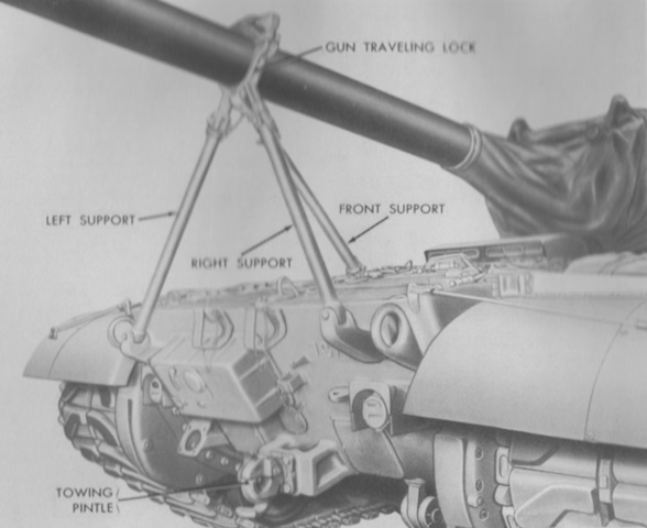
The travel lock is shown erected in this picture, and the towing pintle has been attached to its mounting bracket, leaving its stowage bracket empty. (Picture from TM 9-2350-206-12.)
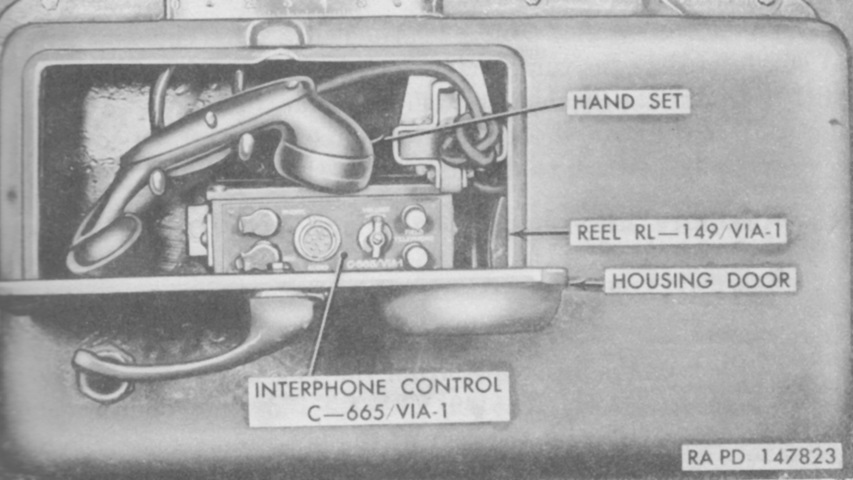
The interphone control C-665/VIA-1 provided dismounts with jacks for an auxiliary handset or headset and microphone, volume control, and telephone binding posts connected to the driver's C-663/VIA-1 and the left loader's C-664/VIA-1. The binding posts could also be used to connect a number of tanks in a party telephone system. The reel RL-149/VIA-1 contained 40' (12m) of cable on a takeup reel; this allowed troops to talk to the tank crew via the left loader's C-664/VIA-1. By pressing the handset switch, infantry could signal the loader via a flashing light; a similar switch on the loader's handset allowed him to flash the light on the housing box of the external interphone (partially hidden by the housing door handle). (Picture from TM 9-2350-206-12.)
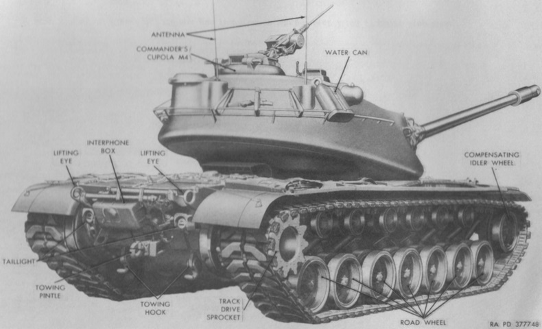
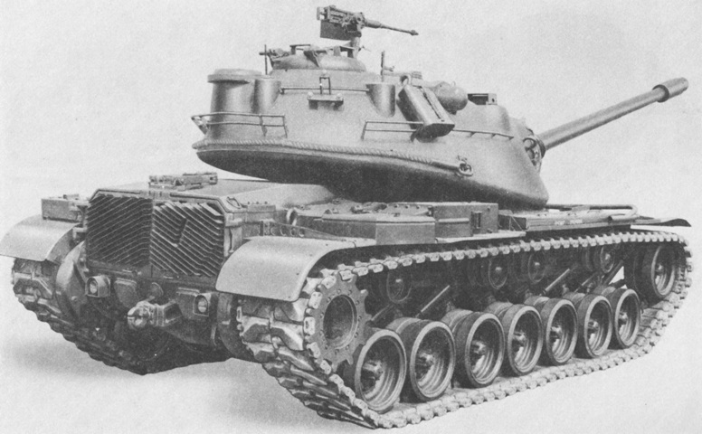
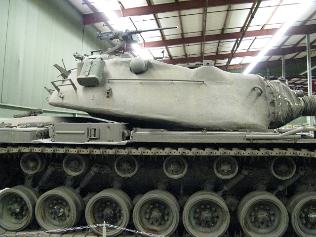
External stowage and the long overhang of the gun tube can be seen from this angle. The gunner and commander entered the turret via the commander's cupola, while both loaders used the loader's escape hatch. Note that the gunner's periscope was mounted in a removable turret roof plate. (Picture from TM 9-2350-206-12.)
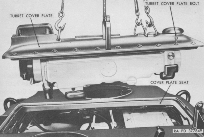
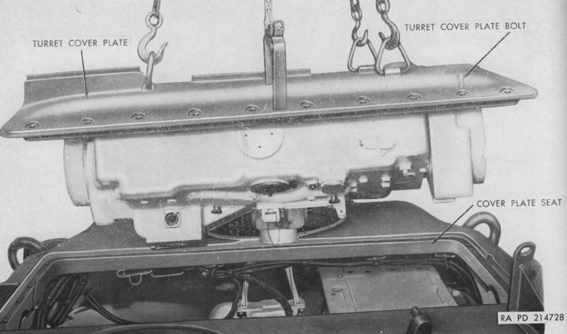
The turret cover plate is shown here being removed, after the armored blisters and end housings were removed from the rangefinder, which is still attached to the bottom of the cover plate. (Picture from TM 9-2350-206-12.)
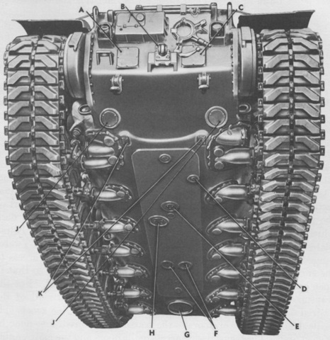
Features and openings in the hull bottom are labeled in this image. The hull was fabricated of cast homogeneous steel armor with a welded floor. A. Transmission left access plate. B. Transmission center access plate. C. Transmission right access plate. D. Auxiliary generator engine drain hole cover. E. Main engine drain hole cover. F. Fuel tank drain hole cover. G. Driver's escape hatch door. H. Main engine oil filter access hole cover. J. Brake rod access plate. K. Transmission drain hole cover. (Picture from TM 9-2350-206-12.)
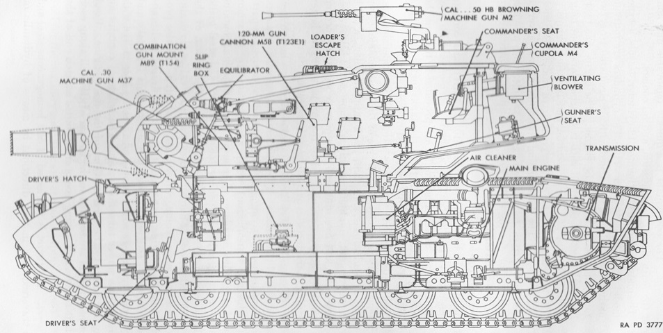
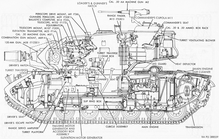
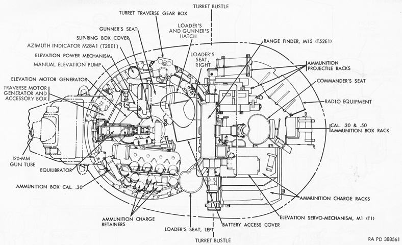
The internal layout is revealed in this sketch. The gunner and commander were both positioned in the long turret bustle. (Picture from TM 9-2350-206-12.)
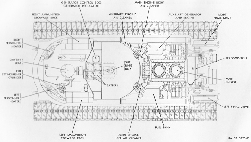
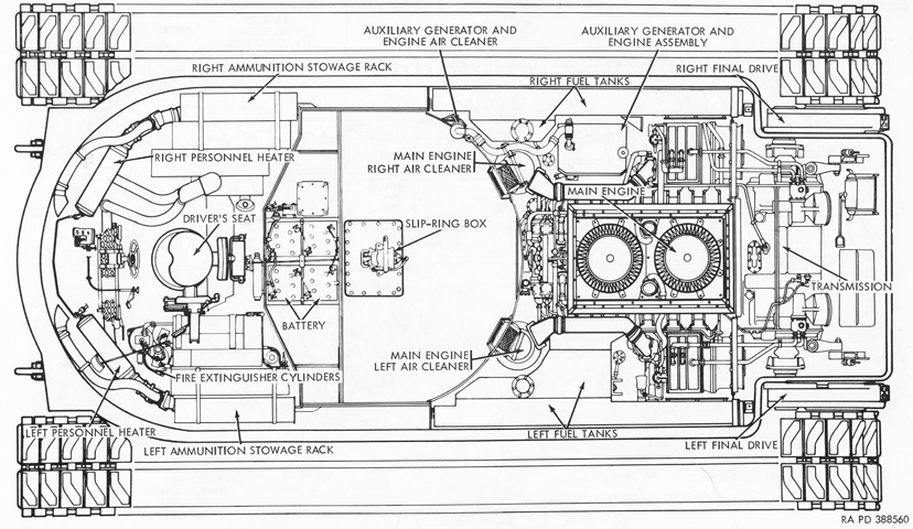
The hull interior is diagrammed here from above. (Picture from TM 9-2350-206-12.)
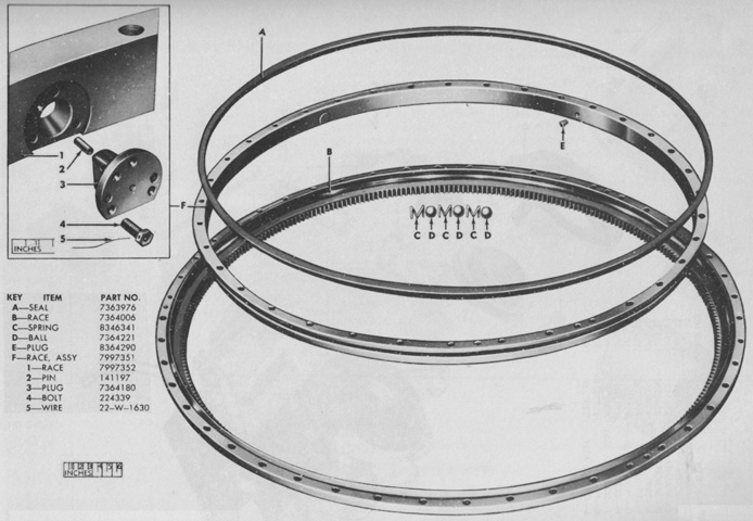
The components of the turret race assembly are shown in this exploded view. (Picture from ORD 9 SNL G-256 List of All Service Parts of Tank, 120-mm Gun, T43E1.)
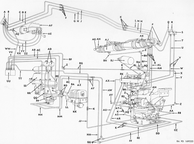
The gun fire control hydraulic lines are the subject of this sketch, seen from the front right. An elevating and traversing hydraulic power pack was suspended from the front of the turret ring, and this provided the hydraulic power for traverse and elevation. The traversing gear box meshed with the turret ring on the turret's right side, and could spin the turret either by manual controls or by the hydraulic motor mounted beneath the gear box. The equilibrator cylinder combined the functions of elevation, equilibration, and shock absorption. In the image above, the equilibrator is labeled AJ, the elevating and traversing power pack is AN, and the turret traversing gear box is SS. (Picture from ORD 9 SNL G-256 List of All Service Parts of Tank, 120-mm Gun, T43E1.)
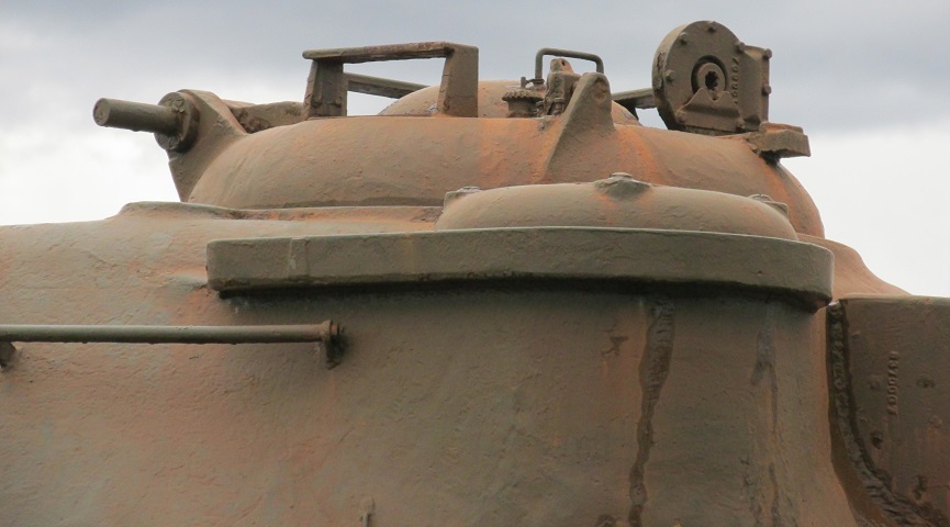
The commander's cupola M4 allowed the .50cal machine gun to be aimed and fired from under armor, although unlike later cupola designs the commander had to unbutton to reload the weapon. Four periscopes M17 were provided in the cupola. The turret ventilating blower is in the foreground, and the cupola is facing the rear of the turret.
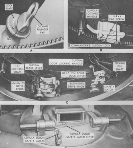
The cupola was like that found on the M48 Patton 48, and the controls are detailed here. A. The locking plunger eye was not to be used due to safety hazard; the cupola door safety latch was to be used instead. B. When pulled down, the cupola locking handle prevented cupola rotation. C. The azimuth drive knob was used to traverse the cupola, and the cupola brake lever was a ratcheting lever used to slow or stop the cupola at a desired point. The elevating drive knob adjusted the .50cal machine gun in elevation, and when pulled downward, fired the weapon. The elevating knob lock lever locked the elevating knob at a desired point. The safety latch prevented the firing of the machine gun. D. The cupola door safety latch lever released the door safety latch, which prevented the cupola door from inadvertently closing due to a sudden stop, etc. (Picture from TM 9-2350-206-12.)
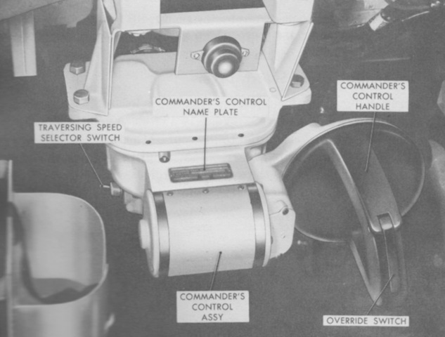
The commander's control handle allowed him to override the gunner's inputs by squeezing the override switch in the heel of the handle. Twisting the black handle clockwise or counterclockwise traversed the turret, and tilting the handle forward or rearward depressed or elevated the main gun mount. A trigger in the handle fired the guns selected. The traversing speed selector switch was used to toggle between high and low traverse speeds. The gunner had a similar switch, but if the commander overrode the gunner, the setting on the commander's switch would take precedence. (Picture from TM 9-2350-206-12.)
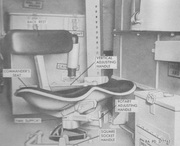
The commander's seat was mounted deep in the turret bustle. It could be adjusted for height as well as rotated around its vertical axis. (Picture from TM 9-2350-206-12.)
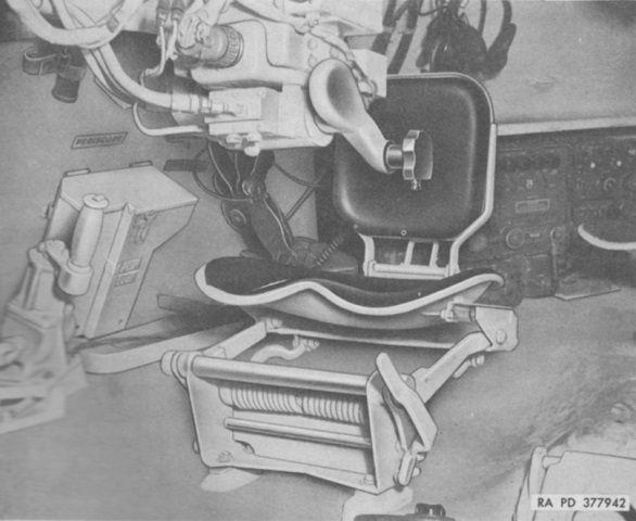
The gunner was just forward of the commander, whose seat can be seen in the background. A bulge in the turret bustle floor accommodated the gunner's seat, and the manual turret traverse mechanism is visible to the gunner's right. (Picture from TM 9-2350-206-12.)
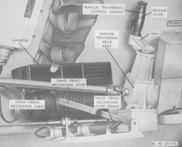
A closer look at the manual turret traverse and manual firing mechanism is provided here. The hand firing mechanism was actuated by pulling the lever up and to the rear; the spring would return the lever to the normal position after use. (Picture from TM 9-2350-206-12.)
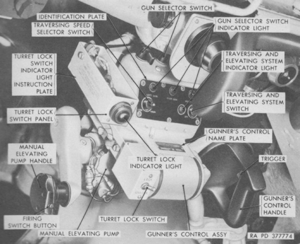
Further controls for the gunner are labeled here. His control handle functioned like that of the commander except for the lack of an override switch. (Picture from TM 9-2350-206-12.)
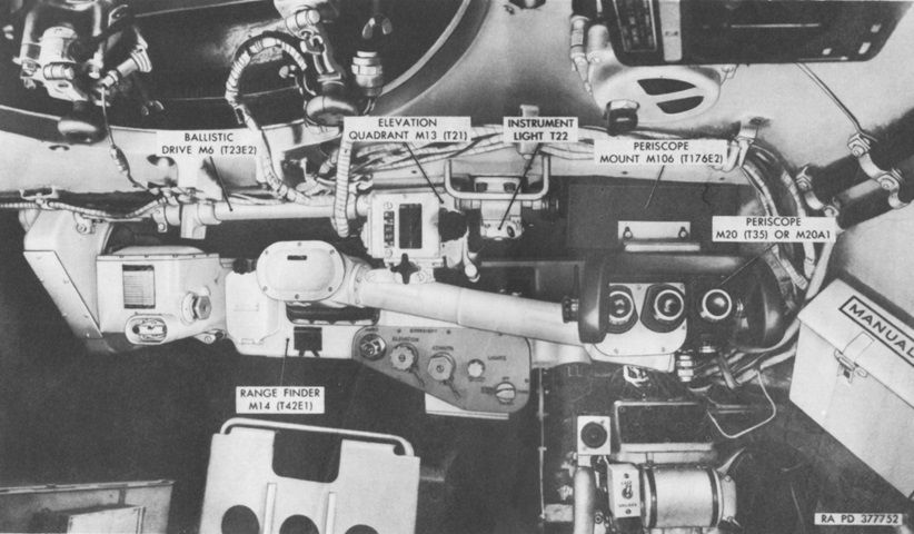
The gunner's sighting instruments are shown here from above and behind his position; the commander's cupola can be seen in the upper left of the picture. The rangefinder M14 was a stereoscopic type with a 5° field of vision and 7.5x magnification, and was the primary targeting device. The M20 or M20A1 periscope was part of the secondary direct fire system. The M20/M20A1 featured a unity viewer with a field of view of 33°18' horizontal and 7°9' vertical, and also a 6x magnification eyepiece with a field of view of 8°. (Picture from TM 9-2350-206-12.)
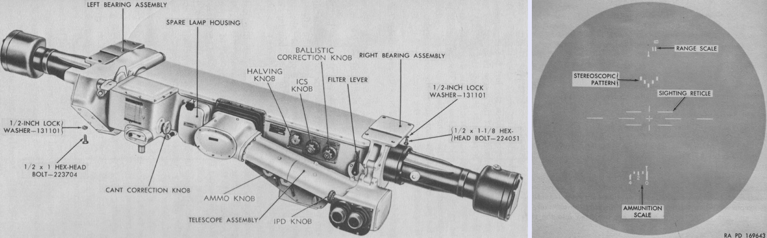
The rangefinder had a 73" (185cm) base and contained two sighting telescopes as well as ballistic computing and transmitting mechanisms. It was 80.2" (204cm) long overall, 23" (58cm) deep, and 14.5" (36.8cm) tall. Its total weight was 400lb (180kg). The ballistic correction knob was graduated in percent of range from -11 to +15% in 1% increments. It allowed the gunner to manually correct for variations in muzzle velocity, air density and temperature, and rear wind. The ammo knob moved the ammunition scale, and was used to set-in corrections for different ammunition types. The proper ammunition scale setting for the different ammunition types was found on the ammunition data chart attached to the rangefinder to the left of the cant correction knob. A bubble level under the ammunition data chart indicated when the proper cant correction angle was obtained.
The rangefinder's sight picture is seen on the right. The sighting reticle was 40 mils across, with the horizontal lines and spaces each representing 5 mils except for the 4-mil spaces directly adjacent to the boresighting cross. The vertical lines and spaces were 2 mils, except for the 1-mil spaces directly adjacent to the boresighting cross. There were 2 mils vertically between the horizontal lines. The stereoscopic pattern appeared to move closer or farther away as the range knob was turned. When the bar at the apex of the pattern appeared as the same range as the target, the proper range was acquired and could be read on the range scale. The ammunition scale showed the corrections input by the ammo knob based on the ammunition data chart. The range scale was nonlinear and graduated from 500 to 5,000 yards (460 to 4,600m), and the ammunition scale ran from 0 to 90. (Pictures from TM 9-6045 and TM 9-2350-206-12.)
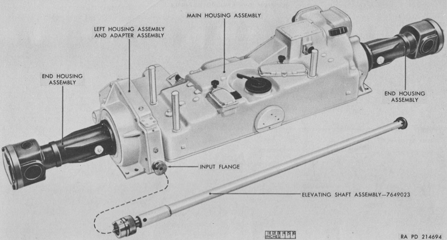
The rangefinder is seen here from the bottom with three support posts mounted, which were used when the assembly was removed from the tank. The elevating shaft assembly rotated with movement of the gun and translated this movement into rotation of the rangefinder via an adapter assembly in the left bearing assembly. (Picture from TM 9-6045.)
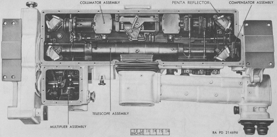
A view of the interior of the rangefinder is provided in this image. The collimator assembly projected illuminated images of the range scale, ammunition scale, and sighting reticles into the telescope assembly via the penta reflectors. The compensator assembly adjusted the stereoscopic focus. Gearing in the multiplier assembly led from the cant correction knob to an adjustable holder and level vial and to a push rod and sighting scale reticle. Turning the cant correction knob adjusted the angle of the parallelogram linkage in the multiplier assembly, which displaced the sighting scale reticle in order that the gun could be traversed and elevated correctly while the reticle was kept on target. (Picture from TM 9-6045.)
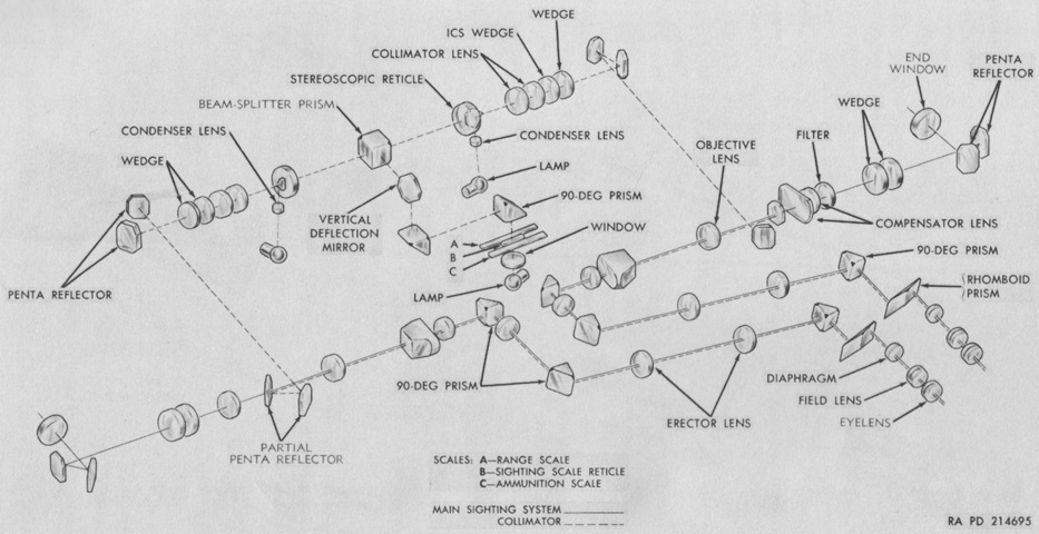
A schematic of the rangefinder M14's optics system is sketched here. (Picture from TM 9-6045.)
The M14's ballistic gearing is shown in this diagram. (Picture from TM 9-6045.)
The periscope M20 is seen mounted next to the rangefinder. The periscope's unity window was to the left of its 6x eyepiece and fitted above the rangefinder eyepieces. An elevating lever on the periscope permitted the gunner to scan up to 20° above the horizontal line of sight. The lever was sprung so that the line of sight would return to horizontal when it was released. Except for having more vertical ranging lines, the measurements of the periscope's reticle pattern matched that of the rangefinder. (Picture from TM 9-2350-206-12.)
The ballistic drive T23E2 was standardized as the M6, and connected the gunner's and commander's periscopes to the rangefinder so that the line of sight remained the same for all during elevation and depression. It included range scales for .30 and .50 caliber machine guns, 120mm high-explosive, and 120mm armor-piercing, and was 30½" (77.5cm) long, 6¾" (17.1cm) wide, 9¼" (23.5cm) high, and weighed 27lb (12kg). (Picture from TM 9-6065 Ordnance Maintenance Ballistic Drives M3 (T23E1), M4 (T23), T23E2 and T24.)
The ammunition stowage racks are shown here isolated from the vehicle. A. Bracket. B. Brace. C. Brace. D. Rack, assy. E. Brace. F. Rack, assy. G. Rack, assy. H. Hanger. J. Mount. K. Rack, assy. L. Bracket. M. Bracket. N. Retainer. P. Mount. Q. Cover, assy. R. Tray, assy. S. Cover, assy. T. Partition. U. Partition. V. Cover, assy. W. Cover, assy. X. Tube, assy. Y. Hanger, assy. Z. Rack, assy. AA. Rack, assy. BB. Mount. CC. Cover. DD. Tube, assy. EE. Tray, assy. FF. Tube, assy. GG. Tray, assy. HH. Cover. JJ. Cover, assy. KK. Mount. (Picture from ORD 9 SNL G-256 List of All Service Parts of Tank, 120-mm Gun, T43E1.)
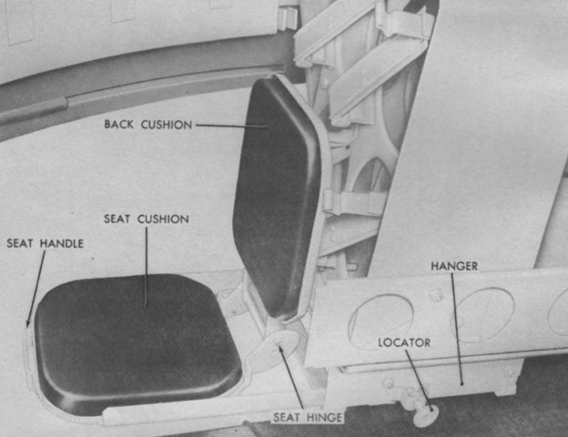
Each loader was provided with a folding seat attached to the left and right turret ammunition racks. (Picture from TM 9-2350-206-12.)
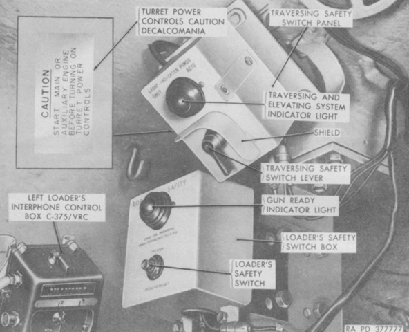
On the top of the left ammunition ready rack support was the loader's safety switch, which was positioned so that the loader needed to move away from the breech to press it. The 120mm gun firing switches would not function until the loader had pressed the safety switch. The traversing safety switch lever would energize the power traversing and elevating system switch at the gunner's position. (Picture from TM 9-2350-206-12.)
This tank is fitted with with the small driver's hatch, meaning it is one of the first sixty produced. Three periscopes M26 or M27 provided forward vision when buttoned, and the hatch cover has a mount for an infrared periscope M24. The fitting to the driver's right was a hookup for the exhaust pipes of the two personnel heaters (mounted in each front corner of the hull), and the small cover on the hull roof to his left rear is where the bilge pump outlet could be mounted.
The driver's station is seen here with the seatback removed. His infrared periscope is secured on the left in the dark bag. (Picture from TM 9-2350-206-12.)
The left side of the driver's position is highlighted in this picture. (Picture from TM 9-2350-206-12.)
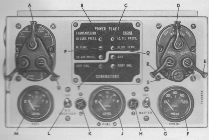
The driver's instrument panel is labeled here. A. Main light selector switch lever. B. Transmission oil low pressure warning light. C. Engine oil low pressure warning light. D. Main engine magneto switch lever. E. Main engine starter switch lever. F. Engine oil pressure gage. G. Master relay switch. H. Master relay switch indicator light. J. Right fuel gage. K. Unused high beam indicator light. L. Blackout receiver switch. M. Left fuel gage. N. Driving light selector switch lever. P. Transmission oil high temperature warning light. Q. Engine oil high temperature warning light. R. Main engine booster switch lever. S. Degasser control switch plunger. T. Main engine generator warning light. U. Release lever. (Picture from TM 9-2350-206-12.)
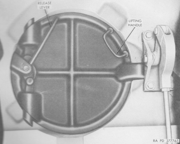
After tripping his seat out of the way, the driver could exit through the hull floor by pulling the release lever on the escape hatch to the rear. (Picture from TM 9-2350-206-12.)
The left side of the combination gun mount M89 is shown here, with a coaxial machine gun mounted. The 120mm gun M58 weighed 6,280lb (2,850kg) complete, with the tube alone weighing 4,600lb (2,100kg). The tube could withstand firing a total of 500 high-explosive M356 projectiles or a scant 150 armor-piercing M358 projectiles. (Picture from TM 9-2350-206-12.)
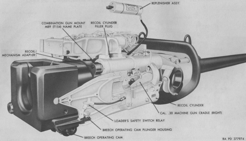
This right side view of the gun mount has omitted the coaxial machine gun. (Picture from TM 9-2350-206-12.)
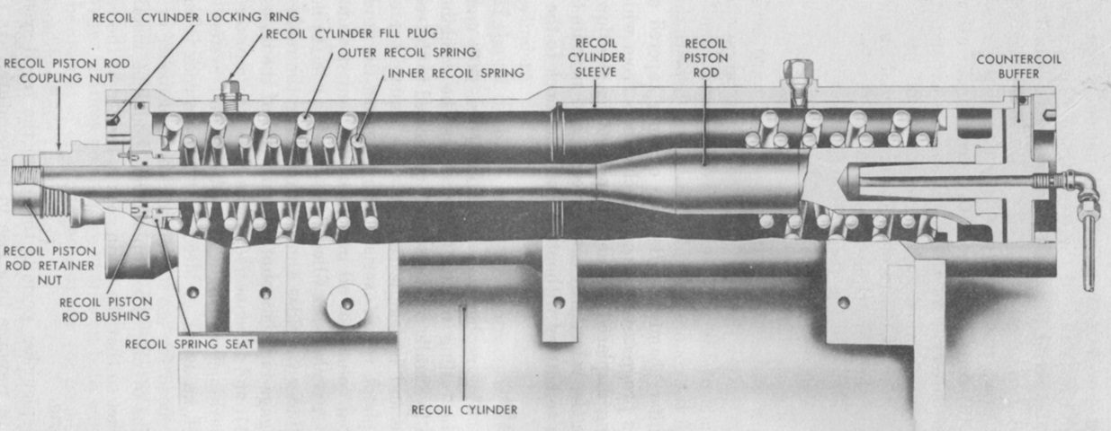
One of the four constant-recoil distance hydrospring recoil cylinders is cross-sectioned in this picture. During recoil, the recoil piston rods, which were attached to the breech ring, moved to the rear. This compressed the recoil springs and passed hydraulic oil through throttling apertures in the recoil cylinder sleeves. The width of these apertures decreased as the piston moved rearward, increasing resistance and, in combination with the springs, stopping the breech. The compressed recoil springs returned the ordnance to battery. Normal recoil length was 13" (33cm), with a maximum of 15" (38cm). Including the replenisher, the recoil system held 20 gallons (76L) of oil. (Picture from TM 9-2350-206-12.)
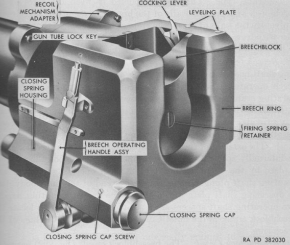
The vertical sliding breech of the 120mm gun would open automatically during counterrecoil and close upon the insertion of a cartridge case. The breechblock weighed ~175lb (~79.4kg). (Picture from TM 9-2350-206-12.)
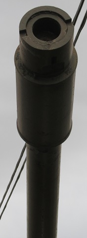
A bore evacuator and cylindrical counterweight were mounted at the muzzle of the 120mm gun. Early counterweights featured two large holes to also act as blast deflectors, but due to ineffectiveness at attenuating target obscuration and concern over the deflector failing at the holes, the front of the deflector was removed, like on this example.
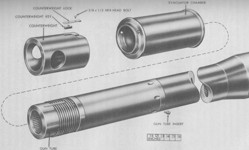
The earlier type of counterweight can be seen here. The jets in the gun tube that allowed the bore evacuator to function can be seen with the counterweight and evacuator chamber removed. (Picture from TM 9-2350-206-12.)
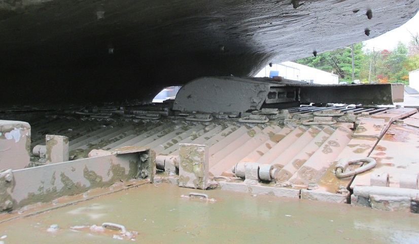
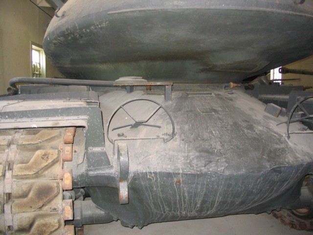
The engine exhaust was provided with deflectors to prevent heating of the gun travel lock, and the mounting points for the turret bustle exhaust deflector can be seen above the exhaust outlet. The main engine access grille side door is facing the camera, and the main engine access center grille doors are in front of and behind the exhaust.
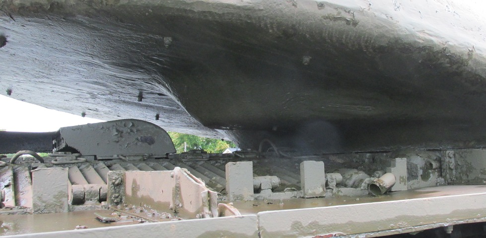
The extreme rear position of the gunner can be ascertained by the bulge for his seat in the turret bustle bottom. One can imagine that the gunner especially appreciated the turret's engine exhaust shield when it was installed! The right-hand main engine access grille side door can be seen, and the exhaust port for the auxiliary engine exits from the front of this door. When in service, the auxiliary engine would have a muffler mounted on the fender.
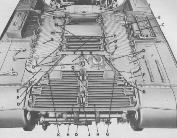
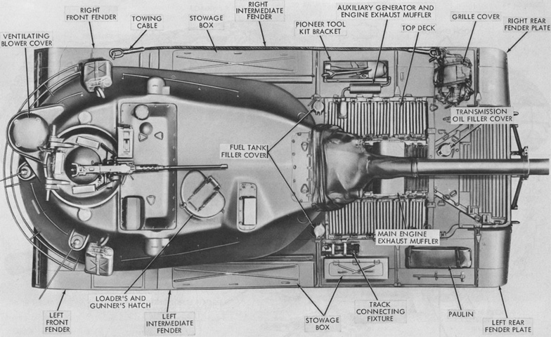
With the turret removed, the top deck can more easily be seen. A. Fuel tank filler cover. B. Main engine access side grille door. C. Auxiliary engine exhaust muffler. D. Lifting eye. E. Transmission access side door. F. Transmission access side plate. G. Right rear support beam. H. Transmission access grille door. J. Center rear support beam. K. Left rear support beam. L. Cross beam. M. Main engine exhaust muffler cover. N. Main engine access center grille door. P. Front support arm. Q. Locking plate. R. Transmission oil filler cover. S. Transmission access center plate. T. Main engine exhaust muffler. (Picture from TM 9-2350-206-12.)
The various engine and transmission access grilles and doors are open here. (Picture from TM 9-2350-206-12.)
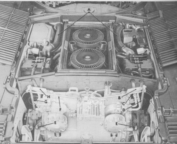
With more structure removed, the engine and transmission compartments can be seen. The letters refer to disconnect points for removing the engine and transmission. (Picture from TM 9-2350-206-12.)
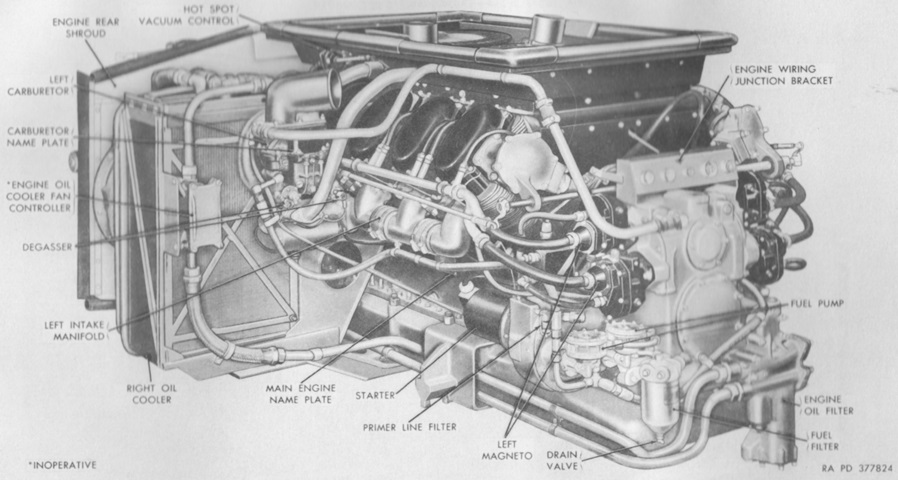
The left front of an AV-1790-7 engine is shown here. Including the flywheel, the engine was 73.70" (187.2cm) long, 59.83" (152.0cm) wide, and 40.84" (103.7cm) tall, and weighed 2,601lb (1,180kg) dry with the flywheel and transmission adapter. The compression ratio was 6.5:1, and bore and stroke were each 5.75" (14.6cm) for a displacement of 1,790in³ (29.3L). (Picture from TM 9-2350-206-12.)
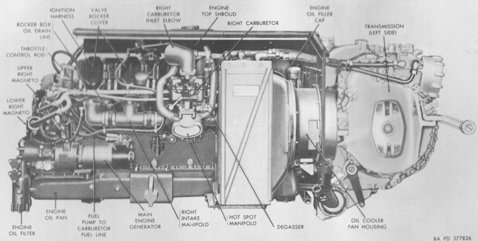
The The AV-1790-7 was fitted with a 150 amp generator, as shown. This differed from the AV-1790-7B, which had a 300 amp generator. An AV-1790-7B would weigh 2,647lb (1,200kg). (Picture from TM 9-2350-206-12.)
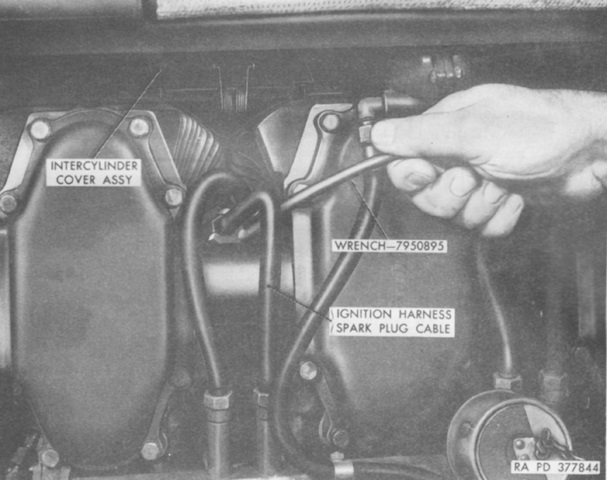
An AV-1790-5B is shown here in the process of having its spark plugs removed. A visual difference between the -5 and the -7 series of engines was that the -5 featured spark plug cables that were crossed going to adjacent cylinders. On the -7 and -7B, these were not crossed. Other differences were that the top surface of the valve rocker arm cover was curved on the -5B but flat on the -7s; the camshaft bearing cap and valve rocker arm shaft brackets were secured with studs on the -5B and bolts on the -7s; the camshaft gear housing cover had smaller ears on the -5B versus the -7s; and the -5B had a hinged sheet metal intercylinder cover assembly installed between cylinders to cover the air passage, while the cylinder fins on the -7s were redesigned to close the air passage. The -5B weighed 2,581lb (1,171kg). (Picture from TM 9-2350-206-12.)
The right rear of the transmission shared with the M48 tank is detailed in this image. It combined power transmission, steering, and braking into a single unit. (Picture from TM 9-2350-206-12.)
The transmission is shown installed in this image. A. Transmission name plate. B. Spark plug access cover. C. Transmission oil filler cap. D. Shifting control lever. E. Transmission oil cooler line. F. Shifting control rod. G. Transmission valve body. H. Transmission oil low pressure warning light switch. J. Transmission high oil temperature warning light switch. K. Steering control lever. L. Transmission oil cooler fan controller (inoperative). M. Steering control rod. N. Transmission main oil filter. (Picture from TM 9-2350-206-12.)
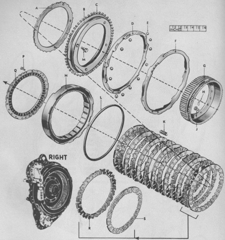
An exploded view of the right brake is diagrammed here. A. Plate. B. Piston. C. Ball. D. Ring. E. Ball. F. Ring. G. Hub. H. Wire. J. Bolt. K. Spring. L. Seal. M. Bolt. N. Anchor, assy. P. Bolt. Q. Plate. R. Plate. S. Plate. (Picture from ORD 9 SNL G-256 List of All Service Parts of Tank, 120-mm Gun, T43E1.)
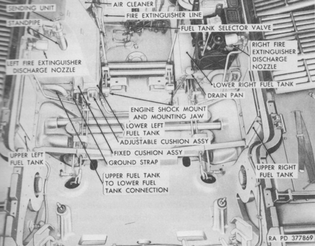
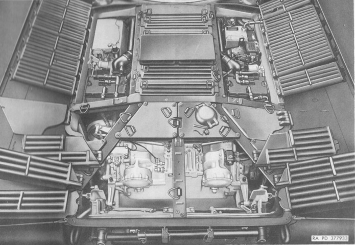
With the engine and transmission removed, the fuel tanks can be seen on each side of the engine compartment. Torsion bars criss-cross the hull floor, and the auxiliary generator and engine are mounted in the right front of the engine compartment. (Picture from TM 9-2350-206-12.)
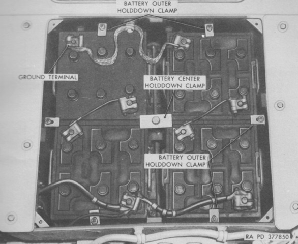
Directly behind the driver's seat, four 12-volt, 100-ampere-hour batteries were connected in series parallel to make a 200-ampere-hour, 24-volt source. (Picture from TM 9-2350-206-12.)
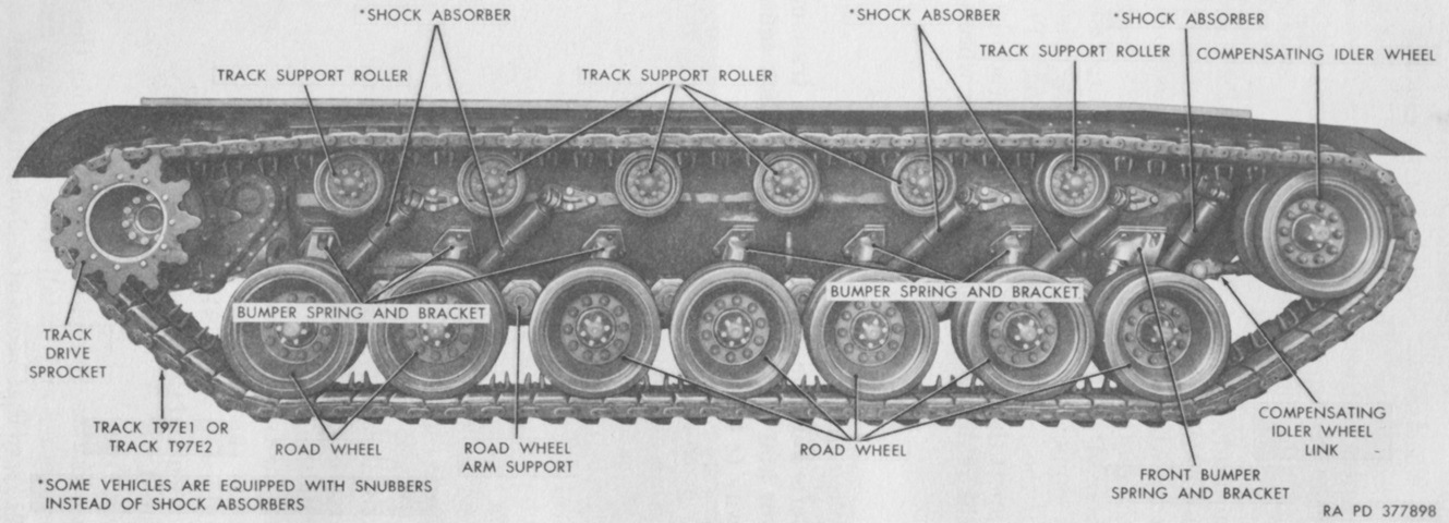
Nomenclature for the busy running gear is given in this picture. (Picture from TM 9-2350-206-12.)
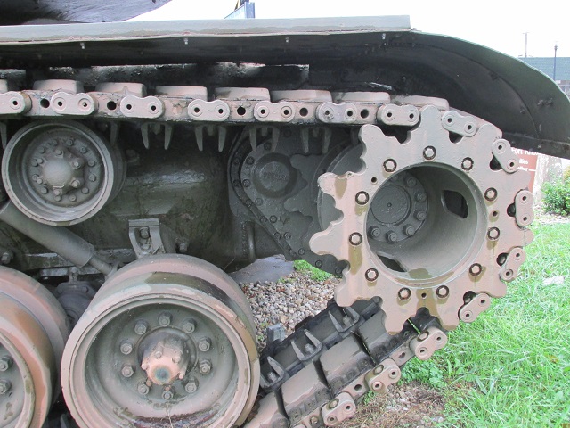
The drive sprocket is highlighted here, along with other suspension components including the rear return roller, road wheels, and shock absorber. The final drive housing can be seen; the final drive spur gear ratio was 7.077:1.
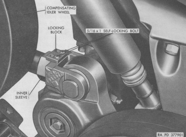
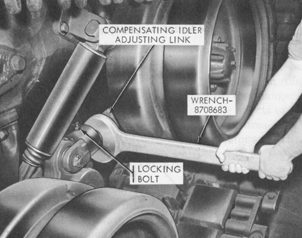
To adjust track tension, the two self-locking bolts on the compensating idler wheel link were loosened, and the locking block was slid back out of the way. Then the inner sleeve was turned clockwise (when looking toward the rear of the tank) to increase tension, and vice-versa. (Picture from TM 9-2350-206-12.)
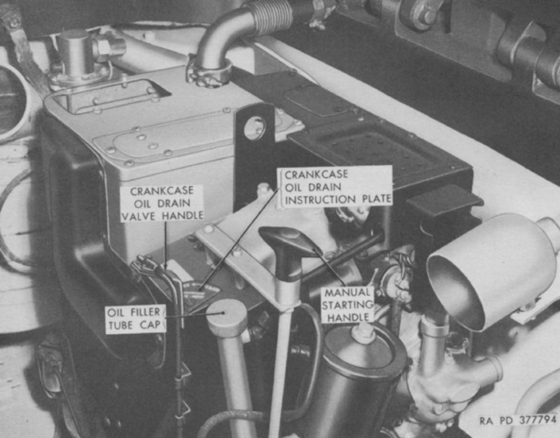
The auxiliary generator engine was a General Motors A-41-1 or A-41-2 1-cylinder, 4-cycle, air-cooled, constant-speed 15-horsepower gasoline engine. It could be started with its manual starting handle or via a control box in the driver's compartment. (Picture from TM 9-2350-206-12.)
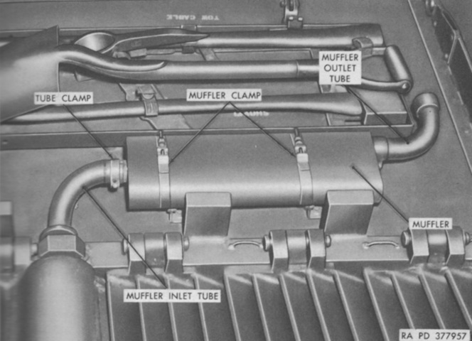
The auxiliary generator engine muffler is shown installed on the right rear fender. (Picture from TM 9-2350-206-12.)
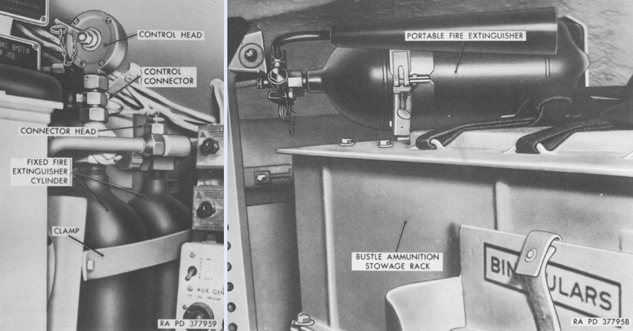
The fixed fire extinguisher system (left) was comprised of three 10lb (4.5kg) CO2 cylinders mounted in the hull front to the driver's left. They were routed to the engine compartment and were actuated simultaneously by pulling the lever on the right cylinder or by pulling the exterior handle on the left front of the hull. If possible, it was recommended to turn off the tank's engine if the extinguishers needed to be used, as their effectiveness was lessened when the engine was on due to the cooling fans discharging the CO2 before the fire could be smothered. Indeed, at 1,100rpm and above the extinguishers would be totally ineffective.
A single portable 5lb (2.3kg) CO2 extinguisher (right) was stowed on the ammunition rack in the left side of the turret bustle. (Picture from TM 9-2350-206-12.)
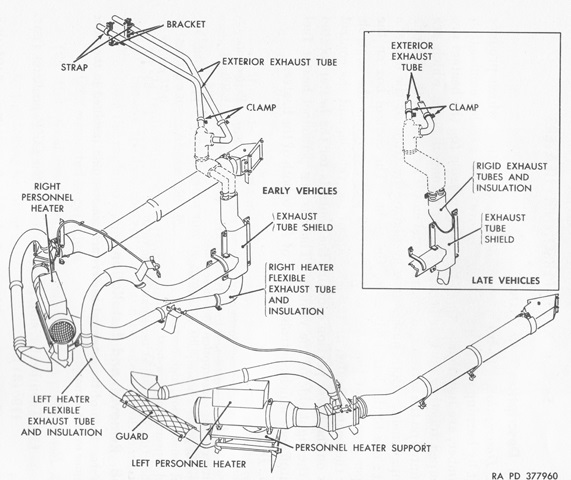
A schematic of the personnel heater layout is sketched here. Two Perfection E500-24 heaters were installed in the tank; burning gasoline, they produced satisfactory operation at temperatures down to -65°F (-54°C). (Picture from TM 9-2350-206-12.)
The forward position of the periscope in turret roof shows the location to which the gunner was moved. The new mount for the commander's machine gun dispensed with the ability to fire the weapon from under armor. (Picture from Standard Military Vehicle Characteristic Data Sheets.)
The gun is shown secured in the tripod travel lock. (Picture from TM 9-2350-214-10.)
The opposite side of the tank is labeled here with its gun forward. (Picture from TM 9-2350-214-10.)
The tank is viewed from the right rear. The gunner's periscope guard can still be seen in its new position. (Picture from TM 9-2350-214-10.)
The forward location of the gunner is obvious when seeing the tank from above. The turret casting was modified around his position and periscope, and his entry and exit was now accomplished through the loaders' hatch. The turret cover plate retained a blanked-off opening for the gunner's periscope, and the rangefinder remained in its previous position, with the commander taking over ranging duties. (Picture from TM 9-2350-214-10.)
The turret cover plate and rangefinder M15 are being removed after the rangefinder's armored blisters and end housings were removed. Note the blanked-off vestigial aperture in the former location of the gunner's periscope. (Picture from TM 9-1240-245-35.)
The turret basket and new location for the gunner are depicted in this cross-sectional sketch. (Picture from TM 9-2350-214-10.)
The hull was essentially similar to the M103's, with the main changes occurring in the turret. (Picture from TM 9-2350-214-10.)
A vertical cross-section of the turret is sketched here, with the turret facing to the left. (Picture from TM 9-2350-214-10.)
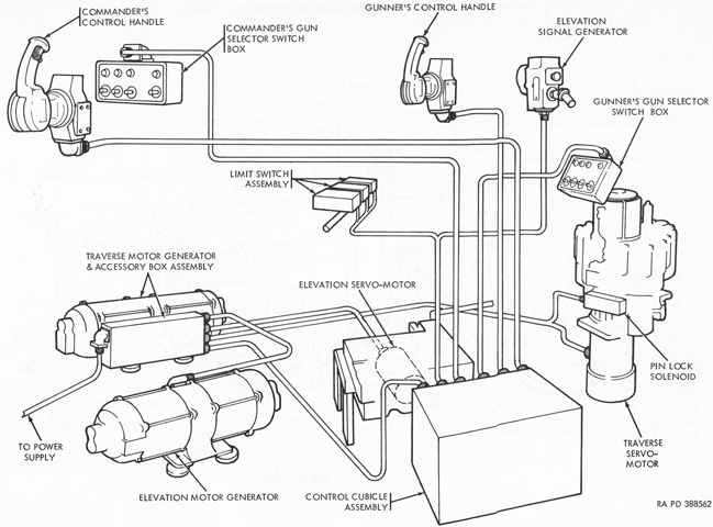
The turret traverse and gun elevation system is shown in this diagram. The traverse motor generator was a constant-speed motor powered by the tank's 24-volt electrical system and a DC generator for operating the turret traverse servo motor. The traverse servo motor received power from the traverse motor generator and moved the turret via a gear train connected to the turret ring gear. The elevation motor generator was powered by the tank's electrical system like the traverse motor generator, but produced AC power to operate the hydraulic elevation power-pump servo motor. (Picture from TM 9-2350-214-10.)
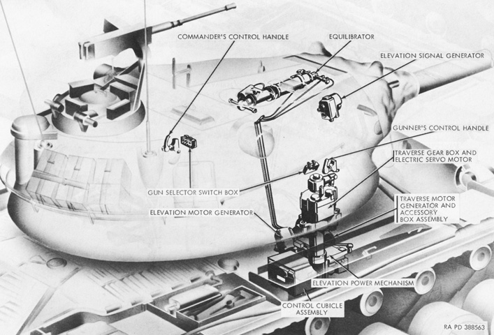
The locations of components of the turret traverse and gun elevation system are seen in this ghosted turret. The equilibrator was again used to elevate or depress the gun, balance the gun, and dampen the shock load. (Picture from TM 9-2350-214-10.)
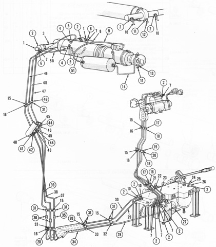
With the turret traverse taken over by the electric amplidyne system, the hydraulics were confined to the power and manual elevation systems. (Picture from TM 9-2350-214-35P/2.)
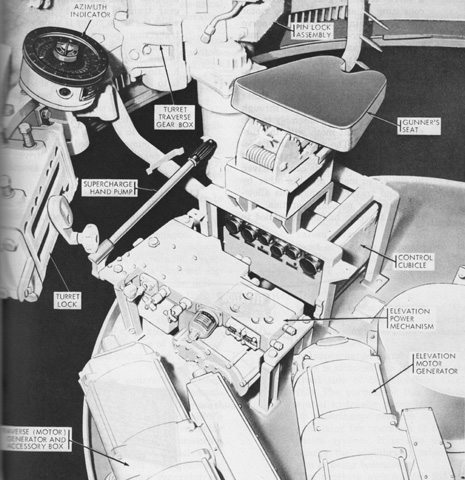
The front right portion of the turret is displayed with the ballistic computer, ballistic computer bracket, gunner's foot rest, electrical wiring harnesses, and hydraulic tubing all removed for clarity. Components of the traversing and elevation system were on the turret basket floor around the gunner's seat, and the supercharge hand pump was convenient to his position. (Picture from TM 9-2350-214-20.)
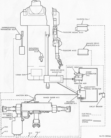
The sighting and fire control system is sketched in this diagram. The commander now operated the rangefinder, and a ballistic computer was added to the system. The gunner's periscope M29 provided unity or 6x magnification, with a 30.7° horizontal and 4.35° vertical field of view. The articulated telescope M102 could pivot to 267 mils above the horizontal boresight position. It had a 7.5° field of view, 8x magnification, and a range of 4,800 yards (4,389m). (Picture from TM 9-2350-214-10.)
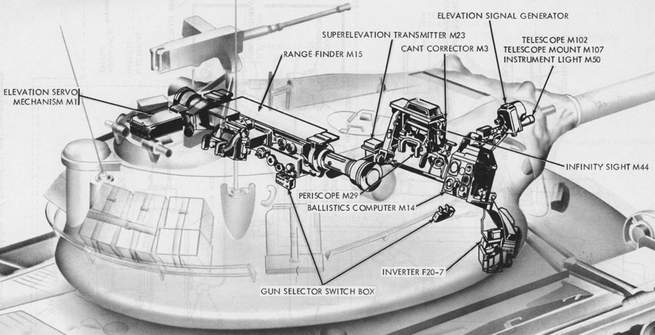
The physical location of the primary fire control and sighting components are seen in this image. (Picture from TM 9-2350-214-10.)
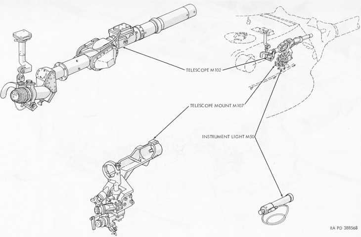
The gunner's telescope M102 and its accessories are drawn here installed in the turret. (Picture from TM 9-2350-214-10.)
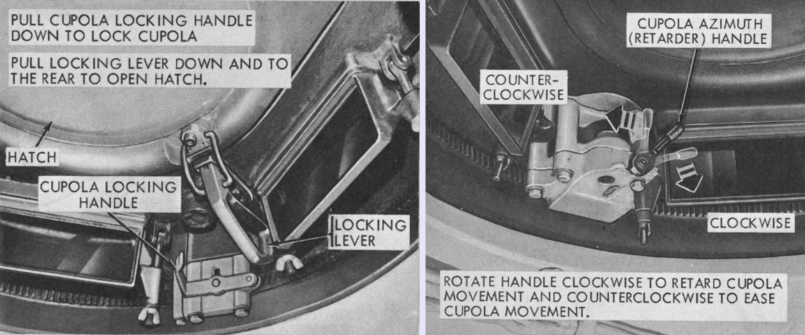
The cupola hatch locking lever and cupola locking handle are shown in the left image, and the azimuth retarder handle on the right. Note that there are no cupola traverse or machine gun elevation handles, as these functions were no longer able to be performed from under armor. (Picture from TM 9-2350-214-10.)
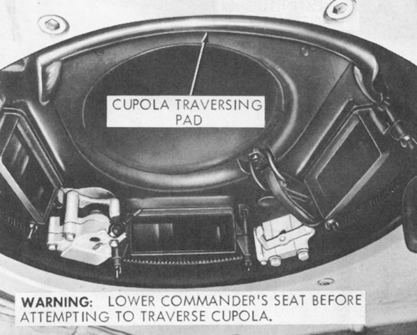
Instead, the commander was to place his back against the cupola traversing pad and use his body to exert pressure in order to rotate the cupola. (Picture from TM 9-2350-214-10.)
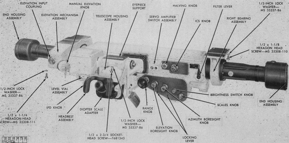
The 8.6x stereoscopic rangefinder M15 is displayed from the top right. It had a 73" (185cm) base, was 80.2" (204cm) long overall, 23" (58cm) deep, and 14.5" (36.8cm) high overall. It weighed 450lb (200kg). The rangefinder was mechanically connected to the elevation servomechanism M1 via the elevation input coupling on the elevation mechanism assembly. This coupling automatically depressed the rangefinder's line of sight so that superelevation could be introduced. (Picture from TM 9-1240-245-35.)
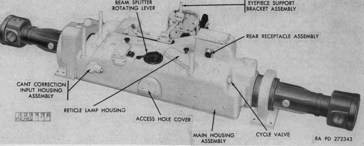
The bottom right of the rangefinder is shown in this picture. It had a 4.3° field of view and could range targets from 500 to 5,000 yards (457 to 4,572m) away. The cant correction input housing assembly connected the rangefinder to the ballistic computer M14 via a junction box. Superelevation transmitted from the ballistic computer to the rangefinder was introduced by this coupling. Initial range data was electrically transmitted from the rangefinder to the ballistic computer by a wiring harness plugged into the rear receptacle assembly. (Picture from TM 9-1240-245-35.)
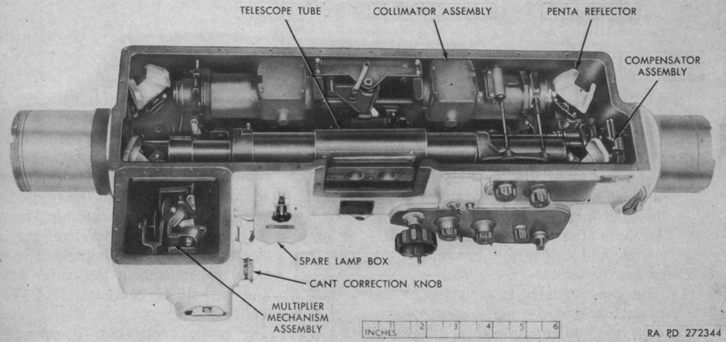
This image details the interior of the rangefinder's main housing assembly. (Picture from TM 9-1240-245-35.)
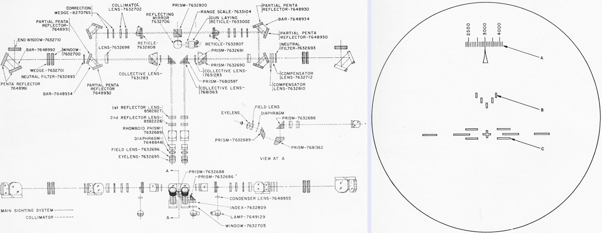
The optical system of the M15 is sketched here on the left, with the reticle pattern on the right. In the reticle drawing, (A) is the range scale, (B) is the stereoscopic pattern, and (C) is the sighting scale reticle. The measurements of the range and lead lines of the sighting scale reticle were the same as those in the rangefinder M14. The increments between the range scale yard graduations increased with greater range values. There was no ammunition scale since the ammunition corrections were performed by the ballistic computer. (Picture from TM 9-1240-245-35.)
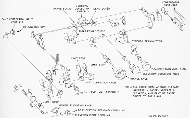
A gearing schematic for the rangefinder is illustrated by this drawing. (Picture from TM 9-1240-245-35.)
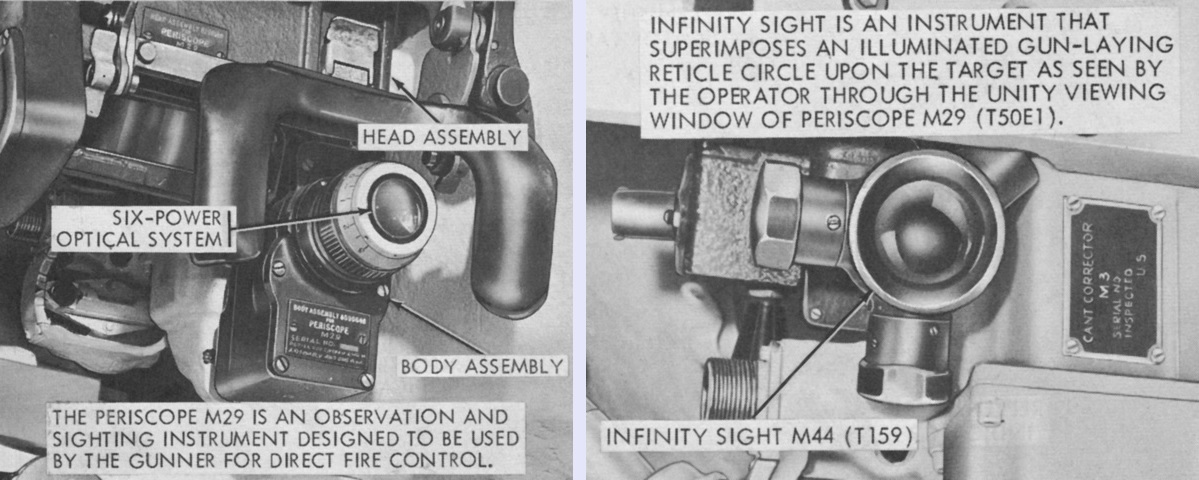
The gunner's periscope M29 is installed in its mount in the left image. The infinity sight M44 on the right could be used to aim the coaxial machine gun. The cant corrector M3 to the right of the infinity sight had knob a on the right of its case that allowed the gunner manually accommodate for up to ±15° of cant. (Picture from TM 9-2350-214-10.)
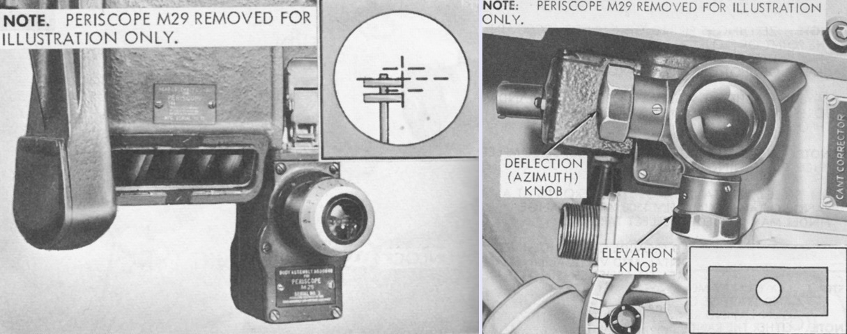
The periscope M29 has been isolated on the left, and its unity window is better visible with the headrest removed. In the inset, its sighting reticle is shown in the process of boresighting using the corner of a telephone pole as a target. On the right, the ring projected onto the unity window by the infinity sight M44 is illustrated in the inset. (Picture from TM 9-2350-214-10.)
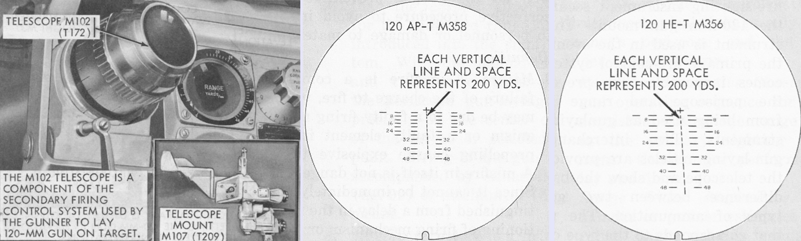
The telescope M102 could be switched between reticles for the M358 AP-T and the M356 HE-T projectiles via a selector lever. Each horizontal line and space represented one lead of 5 mils. (Picture from TM 9-2350-214-10.)
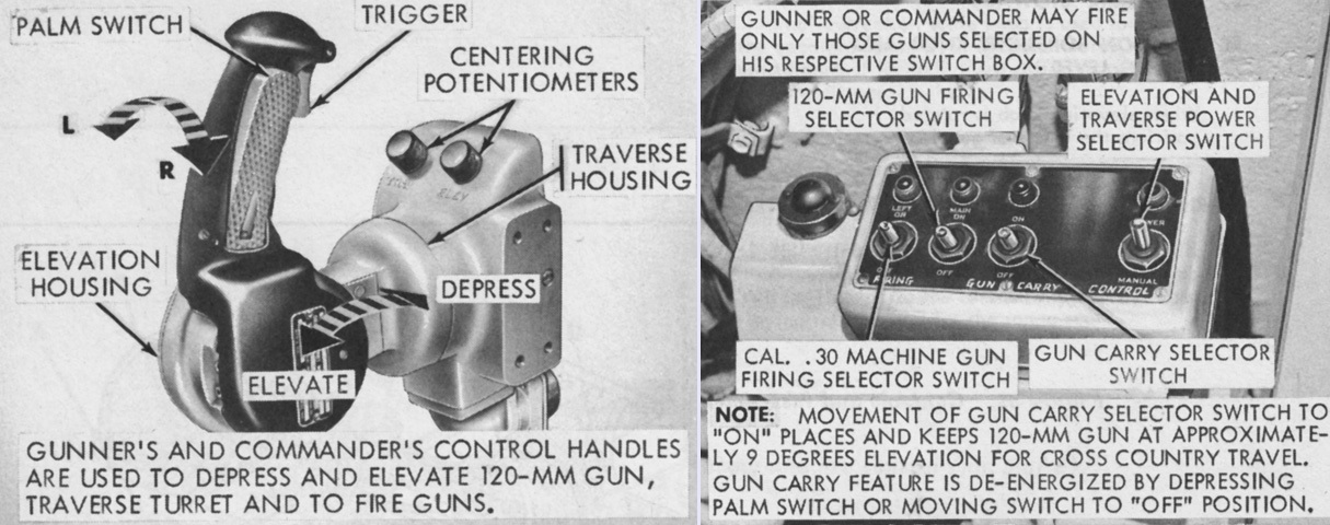
The gunner's and commander's control handles and switch boxes were redesigned. The warning light to the left of the switch box illuminated when the supercharge pressure in the elevation system dropped below 160psi (11kg/cm²), which could lead to sluggish response from the elevation system. A supercharge hand pump was provided to ensure pressure remained adequate. (Picture from TM 9-2350-214-10.)
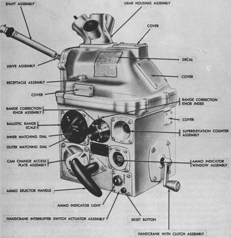
The ballistics computer M14 is shown from the right front. The ammo selector handle allowed the choice of one of three cams representing different types of ammunition. The range correction knob assembly was used to compensate for factors that could affect gun or ammunition performance (e.g., air density; air, powder, gun tube temperature; gun tube wear; etc.). The knob could be dialed in for ±15% in 1% increments, which would be reflected by the range displayed on the inner matching dial. The handcrank could be used to manually transmit superelevation through one of the computer's output gear trains. (Picture from TM 9-1220-207-35.)
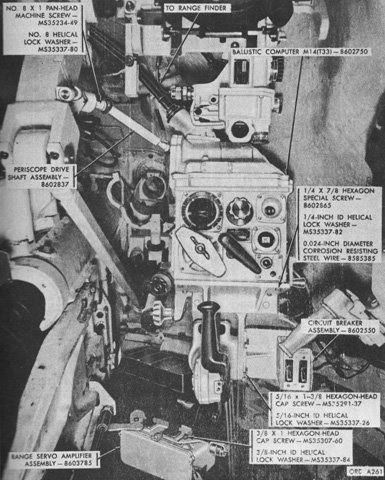
The computer is installed in this picture. It was rigidly mounted under the gunner's periscope M29 and, although mainly operated by the gunner, could also be operated by the commander. Ammunition type and ballistics corrections were inputted manually into the computer, and range data was transmitted automatically from the rangefinder. The computer calculated the required superelevation angle and then transmitted the result mechanically to the gunner's periscope, superelevation signal generator, cant corrector, and rangefinder cant corrector; and electrically to the superelevation transmitter. The periscope's line of sight was depressed by an equal but opposite amount so that, as the gunner returned the sight to the target, the gun would be elevated to the proper angle since the periscope and gun mount were mechanically connected. The signal generator prevented stereodip, where the line of sight of the periscope and rangefinder dropped below the target due to the increasing range signal sent by the rangefinder. This could cause the commander to lose stereo contact, and the signal generator therefore measured the rate of depression and automatically elevated the gun at a rate equal to this depression, which kept the line of sight of the periscope and rangefinder approximately on target. The superelevation transmitter sent the superelevation value from the computer to the elevation servo mechanism. The electrical output from the transmitter to the elevation servo was proportional to the difference between the superelevation and the elevation position signal generated from the gun movement during elevation and depression. This caused the servo to depress the rangefinder line of sight relative to the gun's bore centerline so that the gun needed to be elevated the correct amount to put the rangefinder back on target. (Picture from TM 9-1220-207-35.)
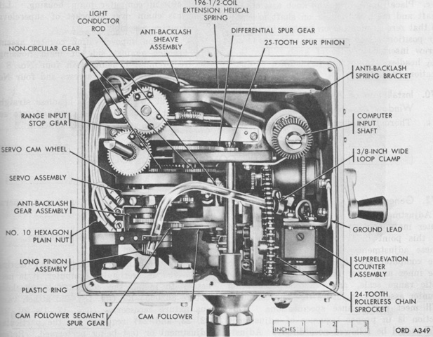
The M14 computer is seen from above with the top cover removed. It was 12" (30cm) long, 19" (48cm) tall, 13" (33cm) deep, and weighed 70lb (32kg). (Picture from TM 9-1220-207-35.)
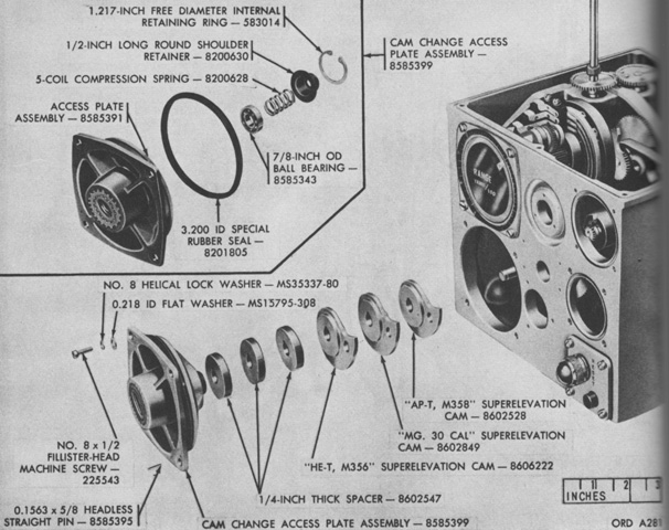
Cams were used to represent the ballistic profiles of different types of ammunition. A cam follower followed the profile of the selected cam as it was rotated. (Picture from TM 9-1220-207-35.)
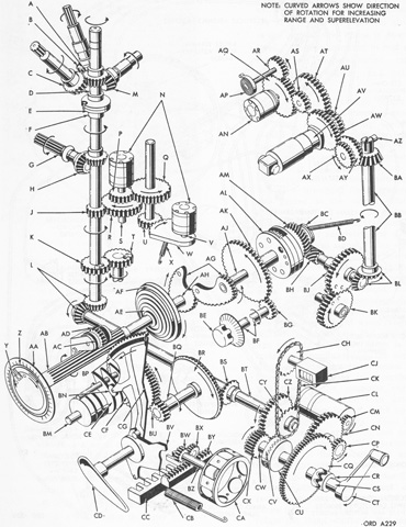
A schematic of the computer M14's gearing is drawn in this picture. A. Output 32-tooth bevel gear. B. Range finder cant corrector 32-tooth bevel gear. C. T16 cant corrector 34-tooth bevel gear assembly. D. Output shaft. E. Coupling. F. Hub assembly. G. Periscope driveshaft assembly. H. Periscope drive 28-tooth pinion gear. J. Output driver 25-tooth spur gear. K. Range output stop gear. L. Output 24 and 24-tooth bevel gears. M. Superelevation signal generator 32-tooth bevel gear. N. Transmitter synchro. P. Output transmitter synchro driver 20-tooth spur gear. Q. Output transmitter synchro driven 128-tooth spur gear. R. Driven 125-tooth spur gear. S. Fine synchro control transmitter rotor shaft. T. Driven 50-tooth spur gear. U. 18-tooth spur gear. V. Coarse transmitter control transmitter rotor shaft. W. 24-tooth gear segment. X. 35-coil extension spring. Y. Inner dial. Z. Outer dial. AA. Range scale. AB. 24-tooth serrated spur pinion. AC. Antibacklash gear torsion spring. AD. Antibacklash 44-tooth spur gear. AE. Servo assembly. AF. Servo cam wheel. AG. Noncircular gears. AH. Inner dial shaft. AJ. Center shaft. AK. Differential spur gear assembly. AL. Differential spider assembly. AM. Differential worm gear assembly. AN. Transformer synchro. AP. Antibacklash 10½ flat coil spiral spring. AQ. Electro-mechanical stop 112-tooth spur gear. AR. Antibacklash 36-tooth spur gear. AS. Input transformer synchro driven 21-tooth spur gear. AT. Input transformer synchro driver 104-tooth spur gear. AU. Input motor driven 26-tooth spur gear. AV. Input drive 1½ ampere motor assembly. AW. Input motor 45-tooth spur gear. AX. Input motor 48-tooth bevel gear. AY. Input driver 48-tooth bevel gear. AZ. Range input idler shaft. BA. Input driven 48-tooth bevel gear. BB. Range input shaft. BC. Antibacklash sheave assembly. BD. Range input antibacklash spring. BE. Range correction knob. BF. Range correction shaft. BG. Range correction 25-tooth spur pinion. BH. 4¼-in (10.8cm) long worm. BJ. Input 48-tooth stop gear assembly. BK. Input 50-tooth stop gear assembly. BL. Input 32 and 32-tooth bevel gear. BM. Camshaft. BN. Rocker arm cam follower roller. BP. 58-tooth cam follower segment spur gear. BQ. Bevel gear driver shaft. BR. 64-tooth bevel gear. BS. 16-tooth bevel pinion. BT. Main shaft. BU. Cam driver 5/16-inch (.7938cm) overall 24-tooth spur gear. BV. Lifter. BW. 48-tooth tab holder wheel spur gear. BX. 54-tooth ammunition indicator spur gear. BY. Ammo indicator rack. BZ. Tab holder wheel shaft. CA. Ammo tab holder wheel. CB. 19-coil extension helical lifter spring. CC. Detent. CD. Ammo selector handle. CE. Superelevation cams. CF. Cam follower. CG. Cam holder 3-13/16-inch (9.6838cm) overall 144-tooth spur gear. CH. Superelevation counter 24-tooth rollerless chain sprocket. CJ. Superelevation mil counter. CK. Rollerless counter drive chain. CL. Servo motor. CM. Servo motor gear 9-tooth spur pinion. CN. Motor train idler 84-tooth spur gear. CP. Motor train 9/16-inch (1.4288cm) overall 24-tooth spur gear. CQ. Clutch 1-9/16-inch (3.9688cm) 144-tooth spur gear. CR. Dog clutch. CS. Handcrank shaft. CT. Handcrank. CU. Splined clutch. CV. Clutch gear. CW. Splined clutch shaft. CX. Handcrank to main shaft ⅝-inch (1.59cm) overall 48-tooth spur gear. CY. Superelevation counter drive 12-tooth rollerless chain sprocket. CZ. Main shaft to handcrank 60-tooth spur gear. (Picture from TM 9-1220-207-35.)
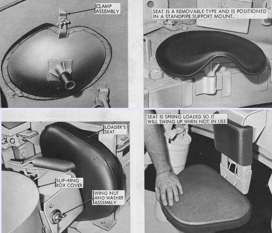
The left loader's seat is stowed and in use in the top left and right images, respectively. The right loader's seat is stowed and in use in the bottom pictures. (Picture from TM 9-2350-214-10.)
A complete round is illustrated being loaded. The type of projectile to be used was determined by the commander, and the loader pushed it into the chamber as far as possible as shown on the left. The cartridge case followed, as on the right, and the breechblock automatically closed as the rim of the case tripped the extractor. (Picture from TM 9-2350-214-10.)
The right-side coaxial machine gun found in the combination gun mount M89 was replaced in the M89A1 with the gunner's telescope M102. (Picture from TM 9-2350-214-20.)
The modified 120mm gun counterweight can be contrasted with the original type above. (Picture from TM 9-2350-214-10.)
Automotively, the M103A1 retained the AV-1790 series engine and CD-850-4 series transmission. The right front of the engine is labeled here. (Picture from TM 9-2350-214-20.)
The track tension system was changed to incorporate a single locking bolt on the idler adjusting link. (Picture from TM 9-2350-214-10.)
Although similar in appearance from this angle to the M103A1, an air cleaner for the new diesel engine is present on the rear fender just in front of the stowage box. Note the number of track return rollers, which indicate that this machine is actually one of the M103A1E1 pilot tanks. (Picture from SL-4-00590B Volume 1.)
The redesigned rear deck and exhaust grille are obvious in this rear view, and a stowage bracket for a searchlight has been added to the turret right rear. (Picture from SL-4-00590B Volume 1.)
The new drive sprocket design used with the longer-pitch T107 track can be seen in this view of an M103A1E1. The engine air cleaner is better visible from the rear ¾ as well. (Picture from SL-4-00590B Volume 1.)
The impressive bulk of the machine becomes apparent when its crew is available for scale. Note the taller engine air cleaner on the rear fender amidst the stowage boxes, indicating this vehicle is powered by the diesel engine. (Picture from Tank Data, volume 2.)
The tank's elliptical hull design is easily seen in this imposing view. In the right-hand headlight group we can see a small blackout marker light and a large blackout service headlight. A regular service headlight would occupy the space beside the blackout marker light, and the tank's horn would be positioned in the upper V-shaped guard between the headlights. On the the tank's left side, the blackout service headlight and another blackout marker light are present, with a blackout drive light in the V-shaped space above the blackout marker light. The service headlight would again occupy the outboard position.
A handrail is visible on the turret side, and a stowage rack lines the rear of the turret, interrupted by the stowage mount for the gun shield-mounted searchlight. An air cleaner for the diesel engine is mounted on the tank's fender. By this stage, remote control operation of the .50cal machine gun had been eliminated, and the commander's cupola had been redesignated M11.
Like the tank directly above, the personnel heater exhaust are present on this tank and routed to the driver's right, and the bilge pump outlet is fitted to his left. The driver was also provided with the larger hatch. The bulge in the turret for the gunner's former position is easily seen on this tank, although he was moved forward in the M103A1.
The exhaust on this tank is vented through M60-style louvres instead of through a port in the rear deck. This redesign necessitated a new gun travel lock, which is in use on this vehicle. The towing pintle is obvious in the center of the rear hull, and above and to either side of this are transmission access plates. Taillight guards are to the outside of the transmission access plates.
Modifications to the tank commander's cupola are visible here compared to the early style on the tank at the top of the page. This latter style did not offer the option of firing the machine gun while buttoned. The structure directly in front of the TC's cupola is a vane sight that assisted the commander in targeting the 120mm gun. The new position of the gunner can be ascertained by the location of his periscope, which is now in front of the turret hatch (the periscope opening in his former position has been blanked off). The receptacle opposite the gunner's periscope was for providing power to the searchlight.
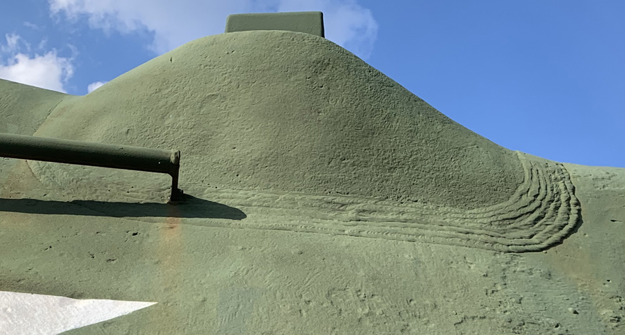
As can be seen in this and the previous images, the gunner's relocated periscope was mounted in a smaller casting welded to the main turret casting.
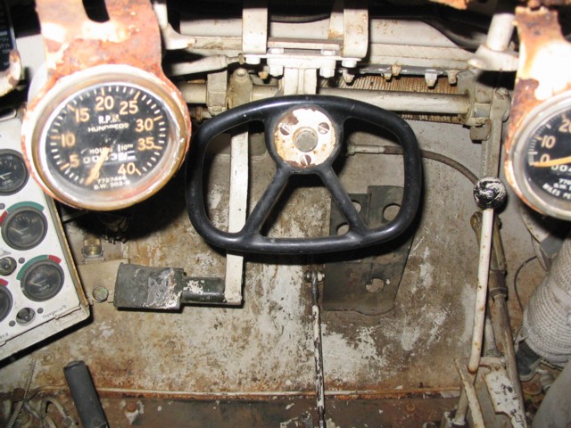
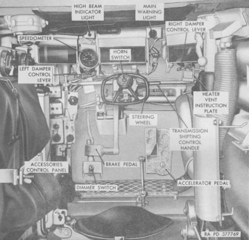
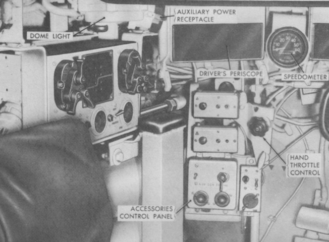
The driver's controls are shown here. The steering wheel is similar to that found in the M48 tank. The tachometer is to the left of the steering wheel, and the speedometer is on the opposite side. The transmission selector lever is visible to the right side of the picture, and the accelerator and brake pedals are on the driver's right and left, respectively. The headlight dimmer switch is just to the left of the brake pedal.
When in reverse, steering the wheel counterclockwise would result in the tank's rear swinging to the right; a leftward movement of the rear was performed by turning the wheel clockwise. Turning the wheel to the right or left while the vehicle was in neutral would cause the front of the tank to pivot to the right or left, respectively.
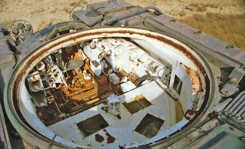
With the turret removed, this hull used for recovery training illustrates the driver's position relative to the ammunition stowage racks on each side. The shape of the side hull casting can also be seen, and torsion bars crisscross the hull floor. (Photo by Richard S. Eshleman.)
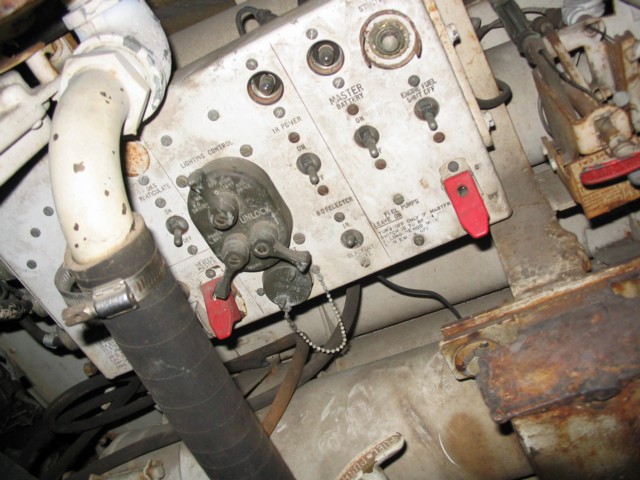
The driver's accessories control panel was placed to his left, and projectile and charge stowage racks are visible behind the panel. Ammunition stowage was placed on both sides of the driver.
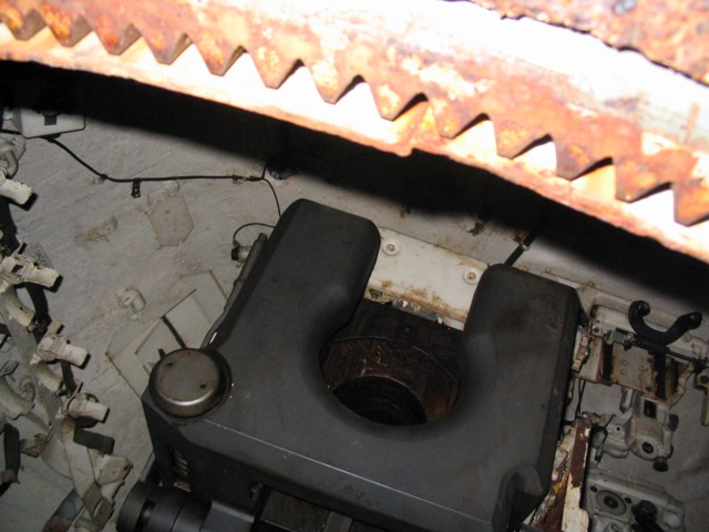
This picture was taken from the driver's compartment looking back into the turret. The breech of the 120mm gun M58 takes up most of this image. The gunner's instruments are visible to its right, and ammunition charge stowage is visible on the opposite turret wall.
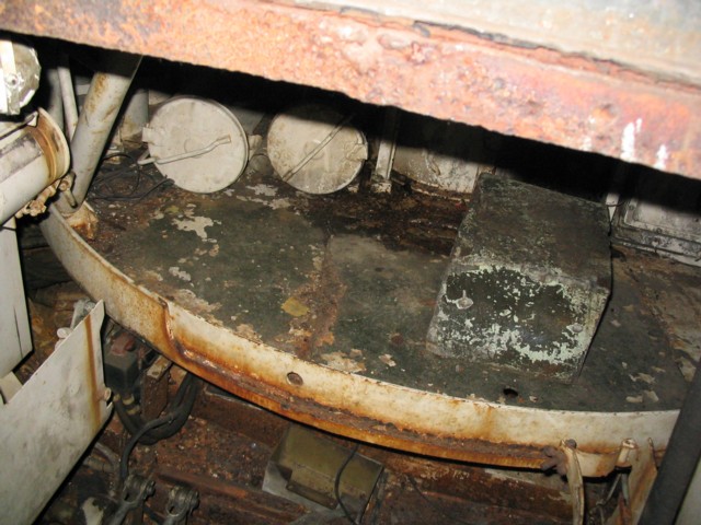
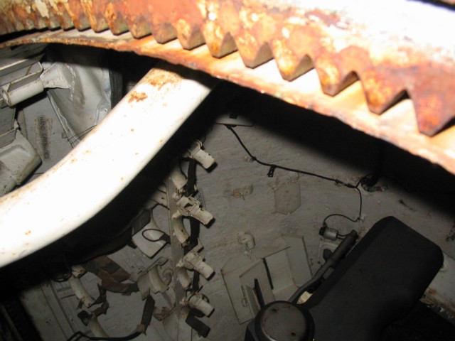
The floor of the turret basket is the subject of this image. The two tubes on the basket floor to the left in the picture are the elevation motor generator and the traverse motor generator and accessory box assembly. Hull ammunition stowage can also be seen to the extreme left of the image.
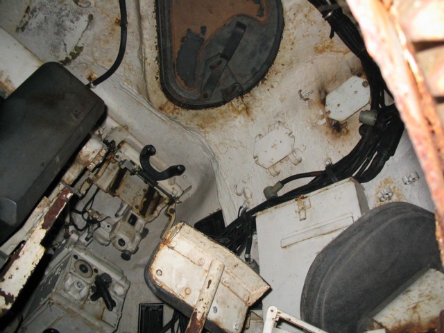
More details of the stowage on the turret's left side are visible here, as well as a seat for the left loader. The box to the front of the turret was for .30cal machine gun ammunition.
The gunner's and loaders' hatch is visible in the turret roof here, and the gunner's position and controls are to the right of the 120mm gun's breech. The M14E1 ballistic computer is on the bottom to the front of the gunner, and a browpad for his sighting instruments is visible near the turret roof. His periscope is missing from this vehicle, however.
