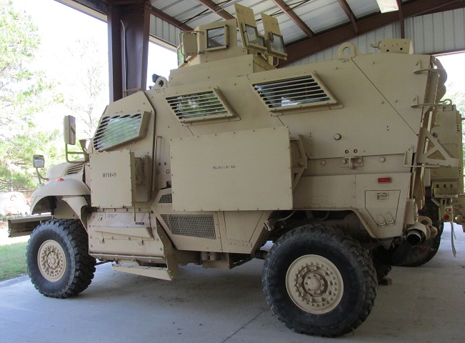
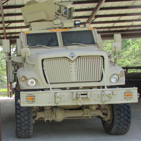
Mine Resistant Ambush Protected Vehicle M1224 MaxxPro.
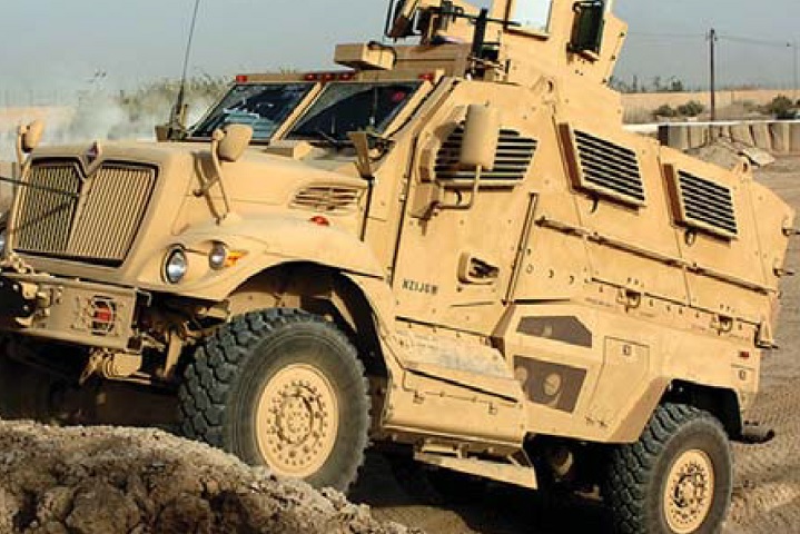
The tall height of the M1224 is one feature that helped it mitigate blasts from mines and buried improvised explosive devices, as the space between the hull and the mine allowed the force to dissipate before striking the vehicle. Two armored windows are present on each side of the passenger compartment, and each of the front doors was also provided with one. The windshields and door mirrors were heated by wires in the glass which were activated by a timed switch. The door mirrors could be adjusted from the inside. The objective gunner protection kit (OGPK) fitted to this vehicle was traversed in azimuth by an electric motor. The fuel tank is located under the step beneath the driver's door, and the mesh screen protected the vehicle's air conditioning condenser. Stowage boxes can be seen in front of and behind the rear wheel. (Picture from MRAP Vehicles Handbook: Tactics, Techniques, and Procedures.)
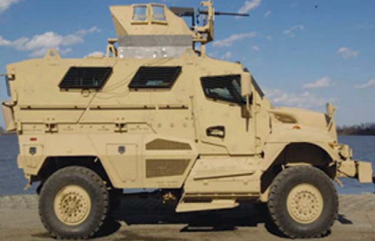
The vehicle's four 12-volt batteries are housed under the step beneath the right-side door. The stowage box in front of the right rear wheel is home to a 110-volt power inverter, NATO slave start connector, and air hose fitting. A 110-volt AC outlet is housed in the stowage box behind this wheel. (Picture from MRAP Vehicles Handbook: Tactics, Techniques, and Procedures.)
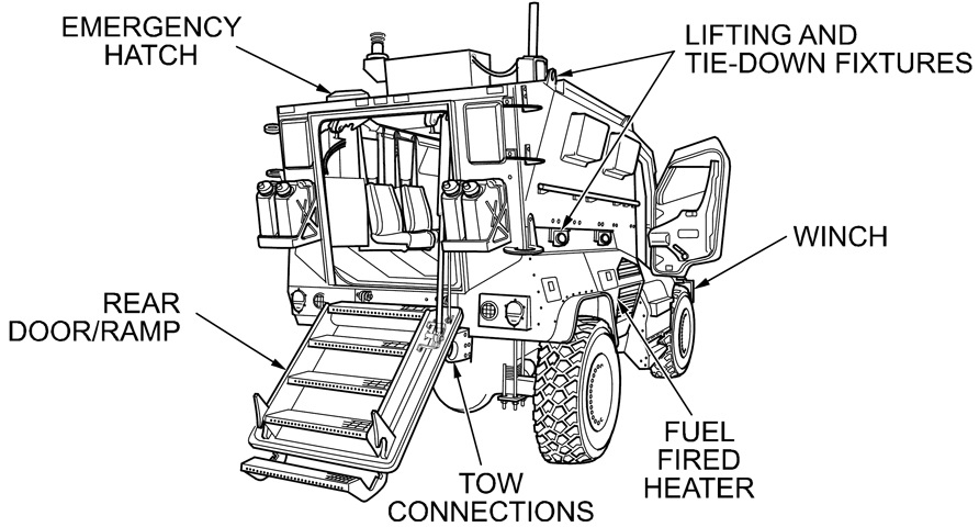
Stowage for water or fuel cans was provided on each side of the rear entry ramp, and stepladder loops climb each of the rear corners of the hull. The hydraulically-actuated rear ramp took a very long 17-19 seconds to lower, which was improved on later Navistar vehicles. (Picture from TM 9-2355-106-10/TO 36A12-1C-2400-1.)
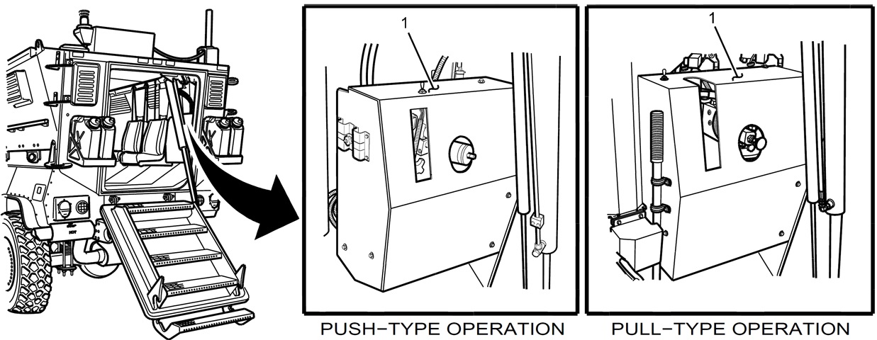
Hydraulic controls (1) for the rear ramp were located in the cabin at the vehicle's rear in addition to at the driver's position. A manual pump handle was included in the case of malfunction or power loss. The plunger on the front of the control was to be put into the neutral position, then the toggle switch on the top was used to raise or lower the ramp. Some models had a second plunger between the vehicle's side wall and the pump cover, and this also needed to be in the neutral position in order to operate the ramp pump electrically. The plungers were to be rotated from the neutral position clockwise or counterclockwise in order to lower or raise the ramp manually. (Picture from TM 9-2355-106-10/TO 36A12-1C-2400-1.)
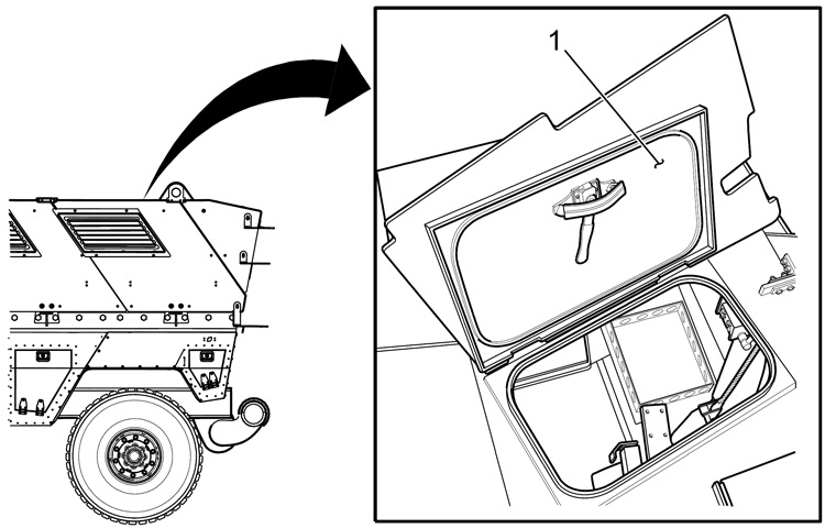
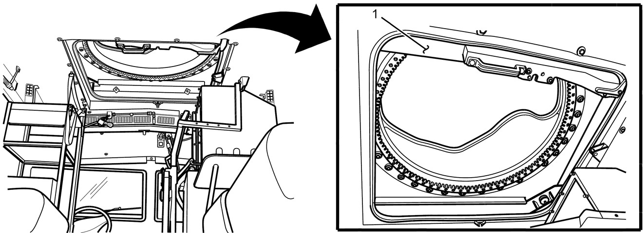
The emergency hatch (1) at the rear of the cabin ceiling labeled in the image above is detailed here. (Picture from TM 9-2355-106-10/TO 36A12-1C-2400-1.)
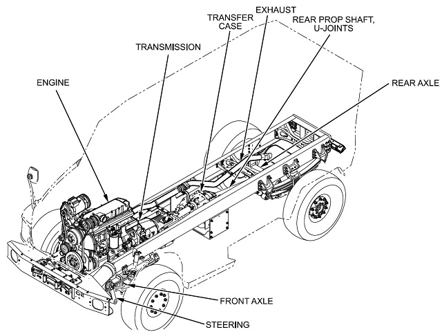
The vehicle frame and powertrain are sketched here. The 530in³ (8.69L) engine had a bore of 4.59" (11.7cm) and a stroke of 5.35" (13.6cm). (Picture from TM 9-2355-106-10/TO 36A12-1C-2400-1.)
The Meritor two-speed transfer case is seen here. In early vehicles, the MTC4210 GCS model was used, while in later vehicles the MTC4210XL-100 was installed. The output from the transfer case drove the rear differential when the vehicle was in two-wheel drive, and both the front and rear differentials when in four-wheel drive. It was necessary to stop the vehicle to shift the transfer case from HIGH to LOW, or when engaging four-wheel drive. If the transfer case was in neutral, the vehicle would not move. (Picture from TM 9-2355-106-10/TO 36A12-1C-2400-1.)
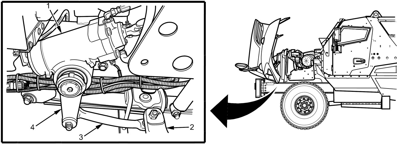
The steering system is illustrated in this drawing. The steering gear (1) was connected to the left steering knuckle (2) by a pitman arm (4) and drag link (3). The front axle was a Meritor MX-18-120 solid beam 18,000lb (8,200kg) unit. (Picture from TM 9-2355-106-10/TO 36A12-1C-2400-1.)
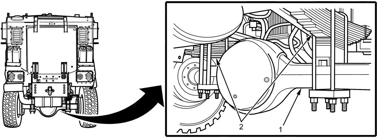
The rear axle (1) was a Meritor RS-23-160 23,000lb (10,400kg) solid beam type; leaf springs (2) were present on both axles. (Picture from TM 9-2355-106-10/TO 36A12-1C-2400-1.)
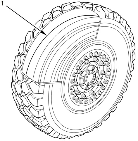
Two-piece bolt-together 20x10.00 Hutchinson runflat wheels were used along with Michelin XZL or Goodyear MV/T 395/85/R20 tubeless radial runflat tires (1), which enabled the vehicle to run at up to 30mph (48kph) for up to 30 miles (48km). (Picture from TM 9-2355-106-10/TO 36A12-1C-2400-1.)
Four Exide lead acid 12-volt, 725CCA batteries were connected in series and parallel to power 12- and 24-volt electrical systems. The batteries were charged by the vehicle's Neihoff 28-volt, 400-amp DC alternator. (Picture from TM 9-2355-106-10/TO 36A12-1C-2400-1.)
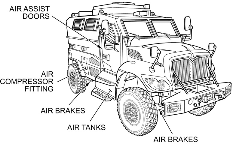
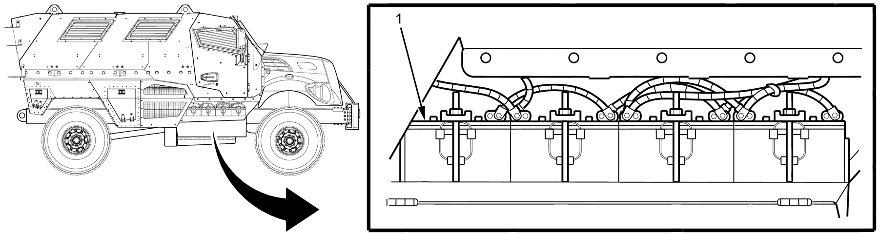
A pneumatic system provided power for the air brakes (2 per axle) as well as assisting with opening the cabin doors. The Bendix Tu-Flo 550 air compressor was driven by the vehicle engine to create the 110-130psi (7.7-9.1kg/cm²) pressure for the brake system. Spring-applied parking brakes on the rear axle were also present. (Picture from TM 9-2355-106-10/TO 36A12-1C-2400-1.)
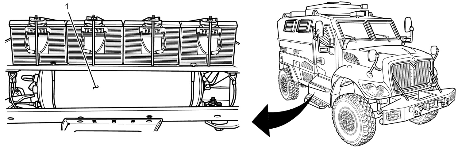
Compressed air for the brakes was stored in tanks (1) under the cabin door. The primary (rear) and secondary (front) brake systems each had their own separate tank. (Picture from TM 9-2355-106-10/TO 36A12-1C-2400-1.)
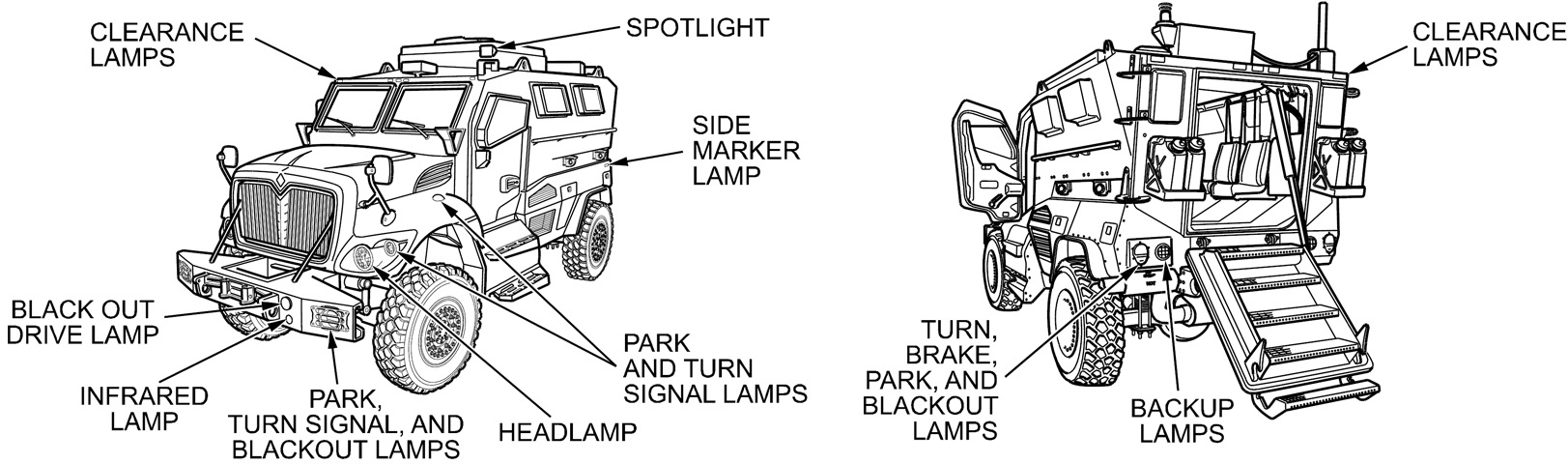
The external lighting systems are detailed in these sketches. (Picture from TM 9-2355-106-10/TO 36A12-1C-2400-1.)
Looking forward into the passenger compartment, the offset seating can be seen as well as the stowed gunner's platform. (Picture from TM 9-2355-106-10/TO 36A12-1C-2400-1.)
The rooftop gunner's turret was accessed via a sliding hatch (1) in the cabin ceiling. The sliding hatch could only be opened when the vehicle was stationary on level ground. (Picture from TM 9-2355-106-10/TO 36A12-1C-2400-1.)
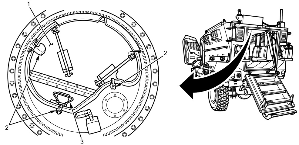
Once the sliding hatch was open, access was granted to the two-piece gunner hatch (1). It was secured by three latches (2), and the front portion of the hatch featured a handle (3) to facilitate opening or closing. (Picture from TM 9-2355-106-10/TO 36A12-1C-2400-1.)
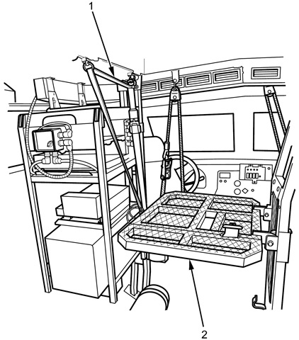
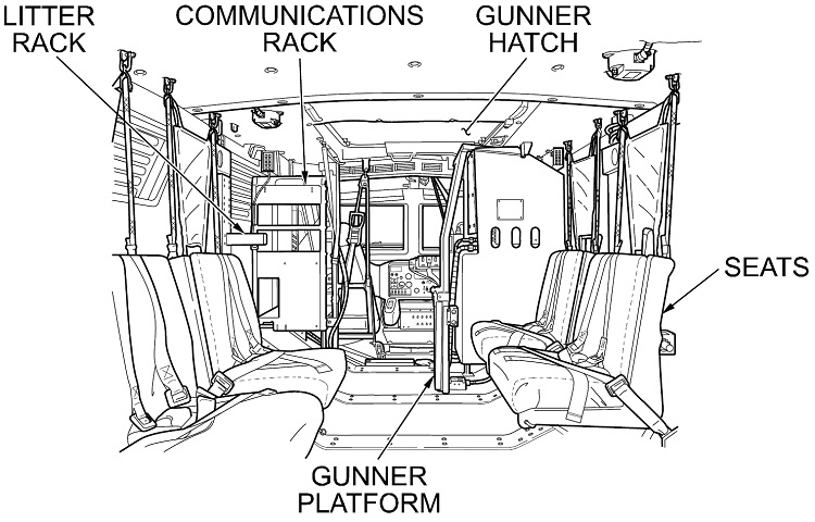
A solid or grated platform (2) could be erected to provide a surface on which the gunner could stand. It was secured by a support strap (1), and on late-production vehicles the platform could also be extended to the side. The communications rack can be seen to the left of the gunner's platform. (Picture from TM 9-2355-106-10/TO 36A12-1C-2400-1.)
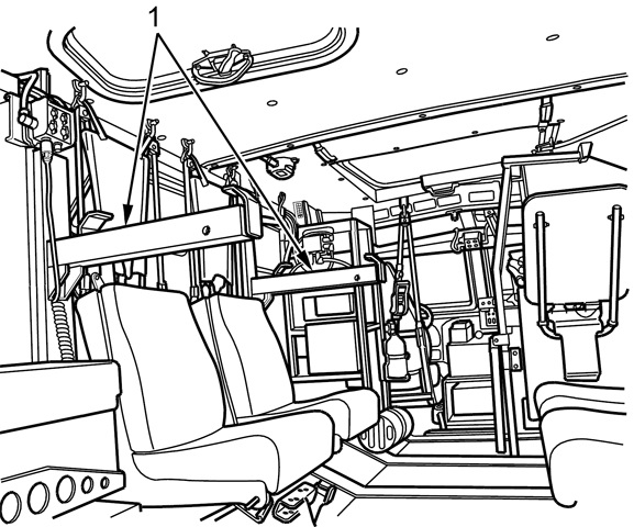
Litter racks (1) could be assembled and installed in the cabin for litter transport. (Picture from TM 9-2355-106-10/TO 36A12-1C-2400-1.)
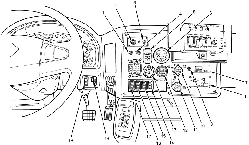
The driver's instrument panel and switches are shown here. 1. Rear crew light switch. 2. Spotlight control toggle. 3. Spotlight switch. 4. Rear door/ramp switch. 5. Rocker switch with four arrows and rocker switch with two arrows [for door mirror adjustment]. 6. HVAC pressure gauge [to measures cabin pressure; normal overpressure was 0.8-2.8 wc (200-700Pa)]. 7. Fuel fired heater timer. 8. Infrared controls. 9. Fuel fired heater switch. 10. Parking brake switch. 11. Trailer air supply switch. 12. Air cleaner gauge. 13. Battery voltage gauge, 24V side only. 14. XFER switch [to put the transfer case into high, neutral, or low ranges]. 15. Front axle switch. 16. EXH brake switch [the exhaust brake was disabled, but its switch remained]. 17. MIR heat switch [to defog windshield and door mirrors]. 18. Main power switch. 19. Ether start button [to inject ether into the engine when trying to start when the temperature is below 32°F (0°C)].
Not labeled are the steering wheel with the cruise control Set/Cruise, Resume/Accel toggle on the right-hand spoke (the Cruise/Throttle on or off switch was on the opposite spoke); and the trailer brake hand control emerging from behind the steering wheel's right spoke. The throttle control and service brake pedals are in their usual location, and the pushbutton transmission selector display is drawn directly to the right of the throttle pedal. On the dash above the throttle pedal is the ignition switch, and the master vehicle light switch is the cluster of buttons above the EXH brake and MIR heat switches. The fire suppression system controls are to the upper right. (Picture from TM 9-2355-106-10/TO 36A12-1C-2400-1.)
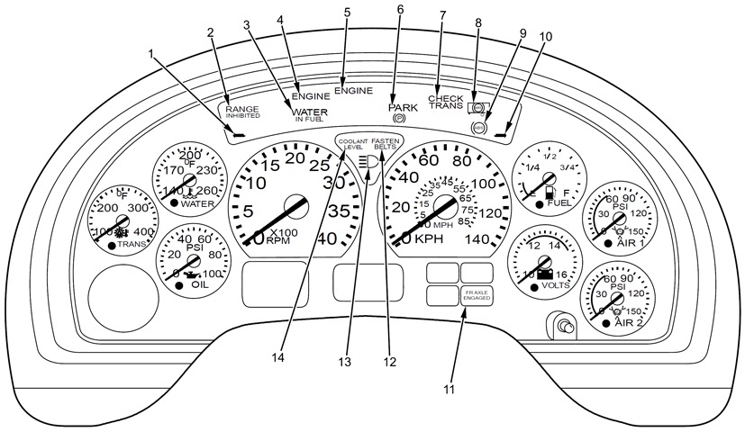
The driver's instrument panel is labeled. 1. Left turn signal arrow. 2. RANGE INHIBITED lamp [illuminated when the transmission was not engaged in the selected gear, and turned off when the gearshift button was adjusted to the appropriate gear]. 3. WATER IN FUEL lamp. 4. ENGINE amber lamp [illuminated in conjunction with other warning lights]. 5. ENGINE red lamp [illuminated in conjunction with other warning lights or messages, indicating a RED STOP alert]. 6. PARK[ing brake] lamp. 7. CHECK TRANS lamp [illuminated when a trouble code was stored in the transmission control module]. 8. Trailer antilock braking system (ABS) malfunction lamp. 9. Vehicle ABS malfunction lamp. 10. Right turn signal arrow. 11. FR[ont] AXLE ENGAGED lamp. 12. FASTEN BELTS lamp. 13. High beam lamp. 14. Low COOLANT LEVEL lamp. The left most dial was for transmission oil temperature, to its immediate right were the coolant temperature and oil pressure gauges, respectively on top and bottom. The tachometer was the large gauge on the left, with the speedometer to its right. The odometer showed in the rectangle centered below the tachometer and speedometer. To the speedometer's upper right was the fuel gauge, and below this was the battery voltage gauge, 12V side only. The button below this was the display/reset button that toggled the odometer display between miles traveled, trip odometer, hours, trip hours, and miles per gallon; and also reset the trip odometer and trip hours. Centered to the right of the fuel and battery gauges was the air pressure gauge #1 for the primary brakes, and below this was the air pressure gauge #2 for the secondary brakes. The air pressure gauges would each illuminate a red warning light and sound an alarm if their readings dropped below 70psi (5kg/cm²). (Picture from TM 9-2355-106-10/TO 36A12-1C-2400-1.)
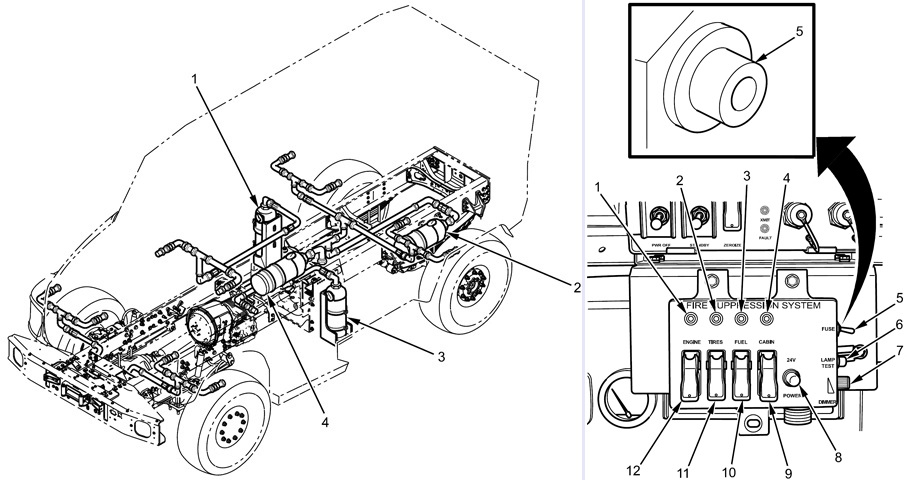
The fire suppression system (FSS) used different agents and cylinders for different areas of the vehicle. HFC227ea Clean Agent was used for the engine (1); Petrotech TM25 for the tires (2); Dry Powder ABC 70 for the fuel tank (3); and water mist for the cabin (4). The cabin and engine systems could be automatically triggered by sensors or operated manually by the driver, while the tire and fuel tank systems could only by triggered manually.
The FSS controls are shown on the right. 1. ENGINE indicator [illuminated when engine FSS was operated, during lamp test, or when cylinder low pressure or an electrical fault were detected]. 2. TIRES indicator [illuminated when tires FSS was operated, during lamp test, or when cylinder low pressure or an electrical fault were detected]. 3. FUEL indicator [illuminated when fuel tank FSS was operated, during lamp test, or when cylinder low pressure or an electrical fault were detected]. 4. CABIN indicator [illuminated when cabin FSS was operated, during lamp test, or when low cylinder pressure or an electrical fault were detected]. 5. FUSE switch [pushed up to turn FSS on or down to turn FSS off. Would automatically switch off if an electrical short was detected. Toggle switch replaced with a push-pull type in later production vehicles.]. 6. LAMP TEST switch. 7. DIMMER switch. 8. POWER on light. 9. CABIN switch. 10. FUEL switch. 11. TIRES switch. 12. ENGINE switch. (Picture from TM 9-2355-106-10/TO 36A12-1C-2400-1.)
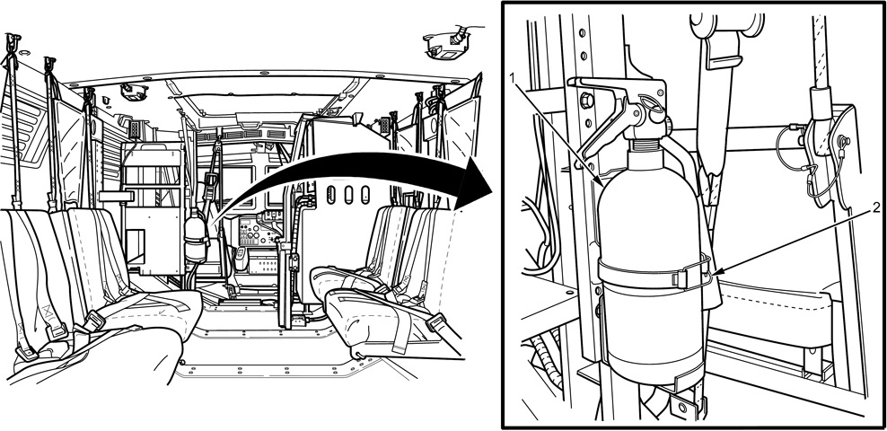
A dry-chemical portable fire extinguisher was also stowed in the cabin. (Picture from TM 9-2355-106-10/TO 36A12-1C-2400-1.)
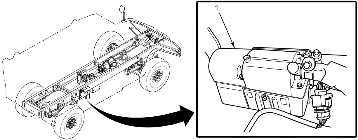
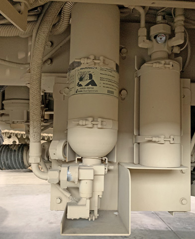
The fuel-fired heater was used to heat engine coolant and could function independently of the engine to heat the cabin. It was operated by a switch or timer in the cabin, and regulated coolant temperature between 65-80°C (150-180°F). (Picture from TM 9-2355-106-10/TO 36A12-1C-2400-1.)
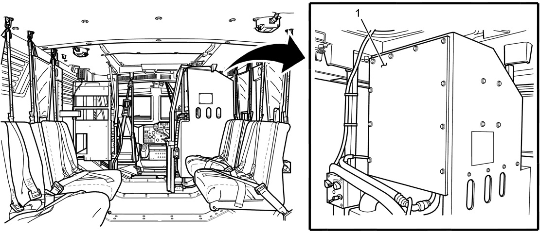
The heating, ventilating, and air conditioning/life support system (HVAC/LSS) (1) circulated fresh air in the cabin, providing protection from extreme external temperatures as well as using a special filter to combat nuclear, biological, and chemical (NBC) agents. The air inlet was located on the vehicle's roof, from which the pretreated air was moved through an evaporator and heater where fresh air was mixed with recycled air. A blower then moved the treated air into the cabin. Overpressure was used to prevent air contaminated with NBC particles from entering the cabin. (Picture from TM 9-2355-106-10/TO 36A12-1C-2400-1.)
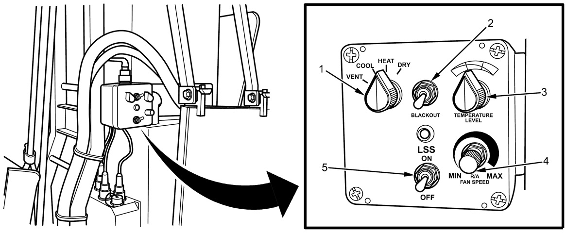
The HVAC/LSS control panel is shown here. 1. Mode control [VENT: Only fresh air from outside entered cabin through NBC filter, if equipped. COOL: Fresh and recycled air were mixed and cooled. HEAT: Maximum heat provided to cabin area. DRY: Defrost mode. Engine rpm would increase to 1,300 within 10 seconds in COOL or DRY modes. Air conditioning would not be provided unless cabin temperature was above 67°F/15°C {sic}.]. 2. BLACKOUT switch [turned off LSS LED]. 3. TEMPERATURE LEVEL switch. 4. RECYCLED AIR FAN SPEED knob. 5. LSS ON/OFF switch. (Picture from TM 9-2355-106-10/TO 36A12-1C-2400-1.)
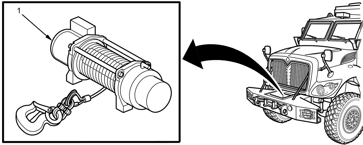
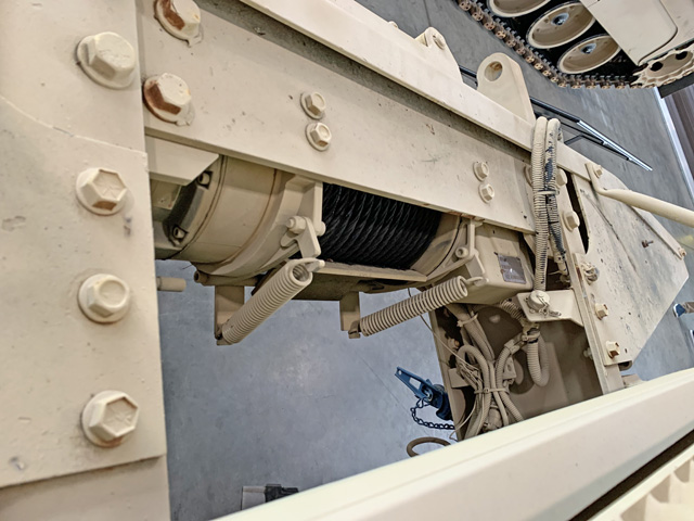
The 12V remote-controlled winch (1) was installed in the front bumper; the cable's ultimate strength was 40,000lb (18,000kg), and the winch was rated to 18,000lb (8,200kg). Since the vehicle weight exceeded the winch's capacity, it was not to be used for self-recovery. The L-shaped winch clutch lever can be seen on top of the near side of the winch; when this was rotated away from the winch drum, the winch clutch was disengaged and free-spooling was possible. (Picture from TM 9-2355-106-10/TO 36A12-1C-2400-1.)
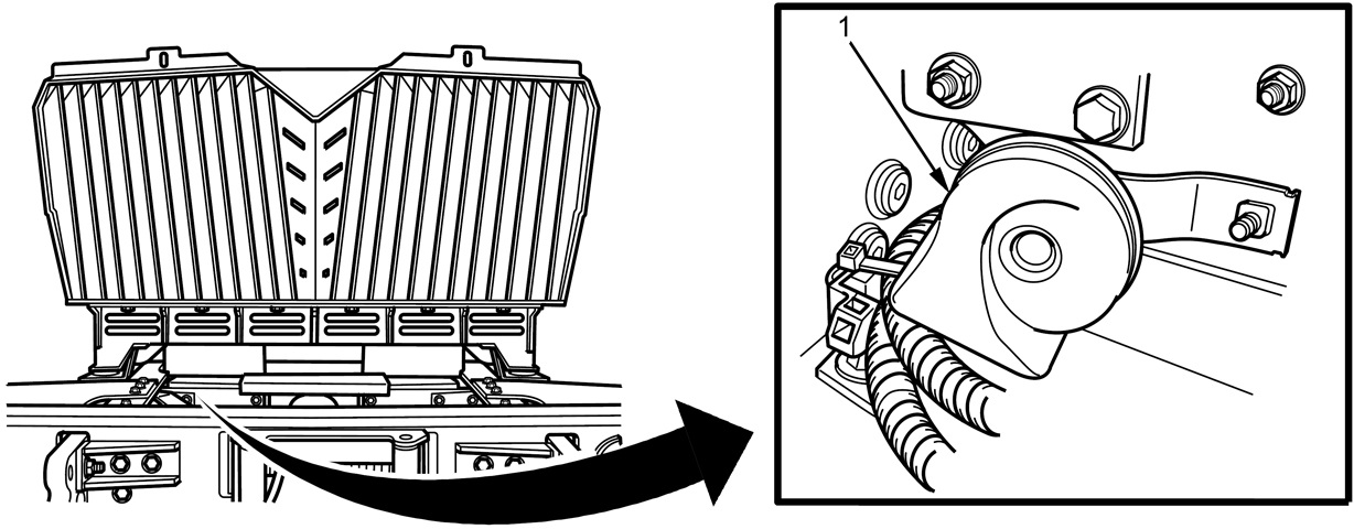
Two horns were installed behind the front bumper, and were activated by a push-pad on the steering wheel. (Picture from TM 9-2355-106-10/TO 36A12-1C-2400-1.)
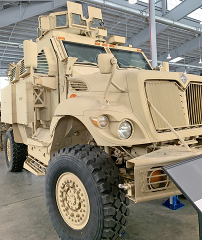
Compared to the above vehicles, the applique standoff MEAP kit is obvious on the door and passenger compartment. Note that the door handle now extends below the armor kit since it covers the handle's previous location.
The increased width imposed by the MEAP kit can be seen when looking down the side of the vehicle. The outlet for the cable of the electric recovery winch is in the front bumper, and the spotlight is above the driver in front of the OGPK. The increased weight led to the fitting of sturdier 25,500lb (11,600kg) rear axles.
The gunner in the OGPK was provided with rear-view mirrors, one of which can be seen here.
The front of the roof above the drivers' positions is shown here. The mount for the AN/VAS-5 thermal viewer is attached to the roof closest to the camera, however the viewer itself is not present. Beyond is a housing for a transceiver for the Blue Force Tracker system.
The OGPK provided the gunner with vision through transparent armor modules to the front and sides, including the machine gun shield.
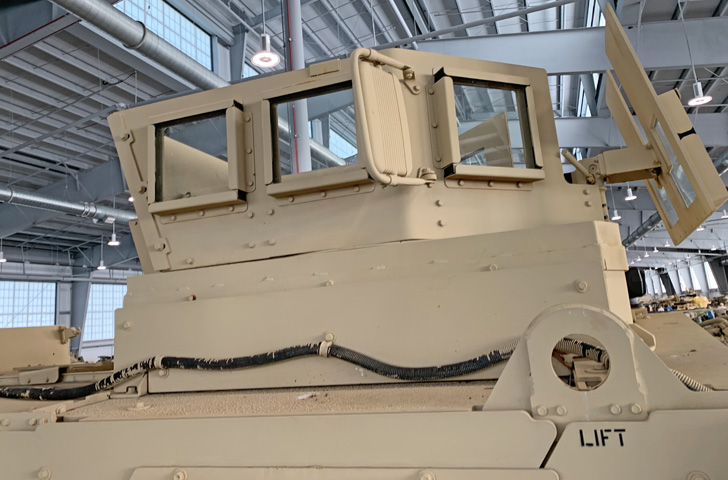
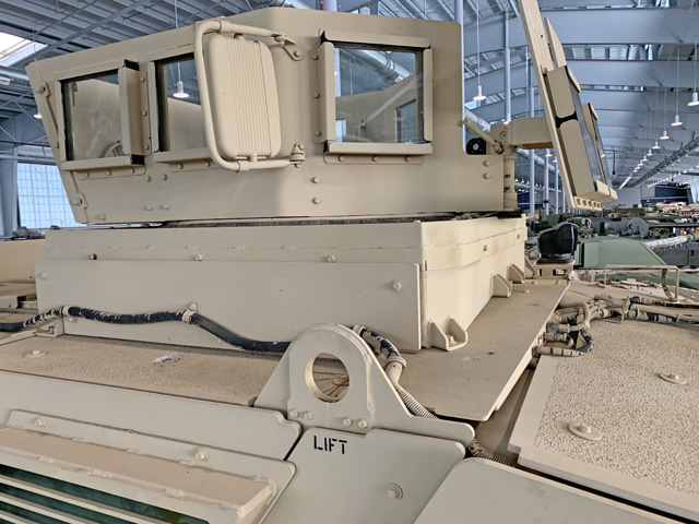
The rear plate of the OGPK was solid, and the mirrors would provide visibility to the rear.
The bottom step of the rear ramp reached above the roof when the ramp was closed. The solid rear armor plate of the OGPK is better seen here, along with the OGPK's rear-view mirrors.
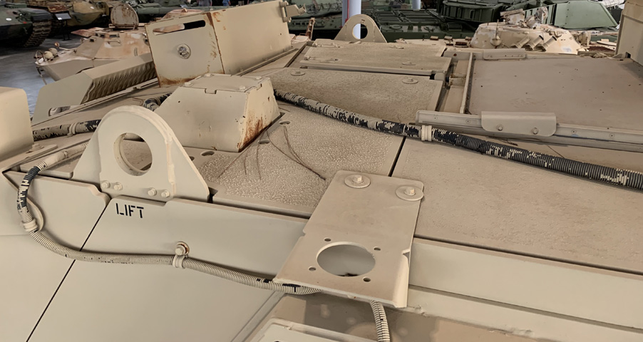
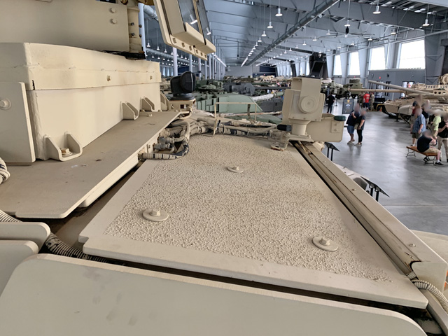
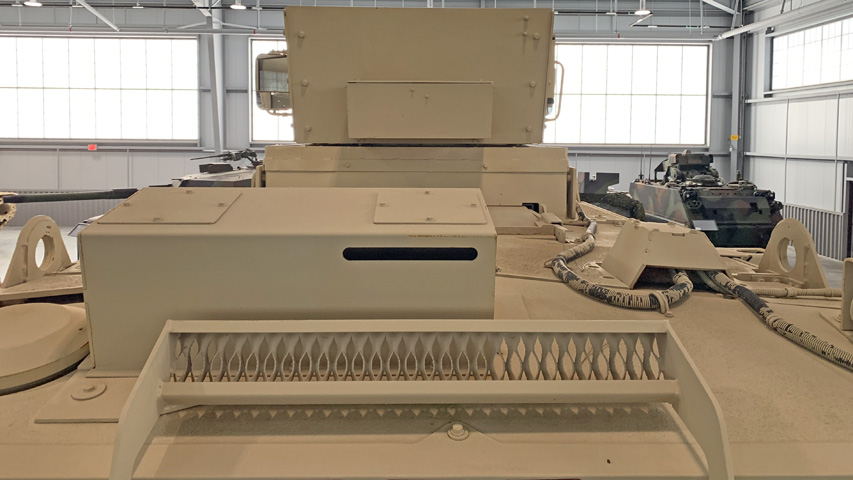
The roof behind the OGPK is seen here. The sliding rails for the gunner's roof hatch are visible to the right, and the rooftop emergency hatch can be seen adjacent to the lifting fixture on the opposite side.
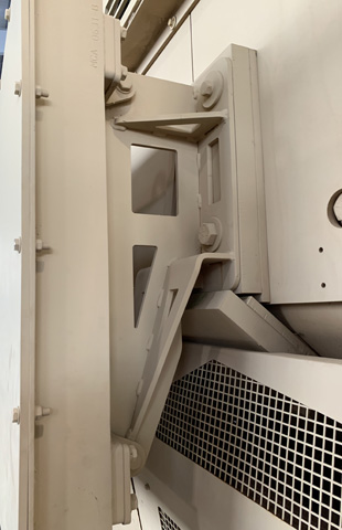
The supporting bracket for the passenger door MEAP armor is detailed in this image.
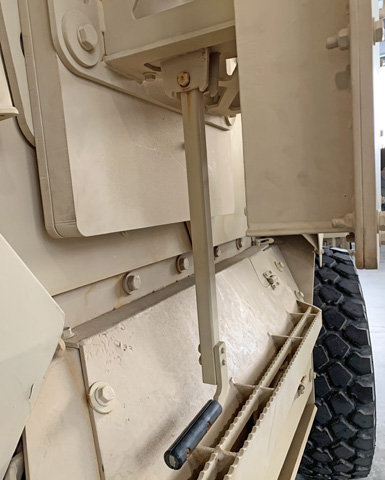
With the MEAP armor module blocking so much of the door's exteriors, an extension was necessary to actuate the door handle. The extension is seen here with its black handgrip reaching below the armor module.
Similarly, the passenger-side rear armor support is shown here.
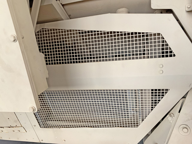
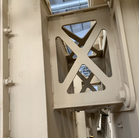
The mesh screen on the passenger side protected the air conditioner radiator.
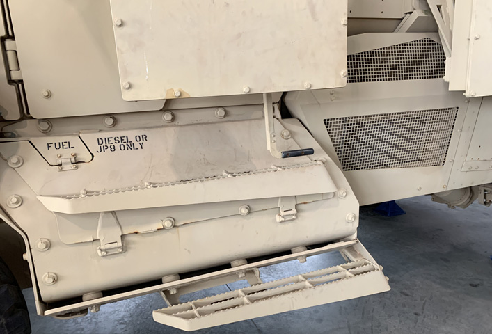
The left fuel tank is seen in this picture, with non-slip steps attached to ease entry into the cab. The door handle extension is visible emerging from the bottom of the MEAP armor mounted to the driver's door.
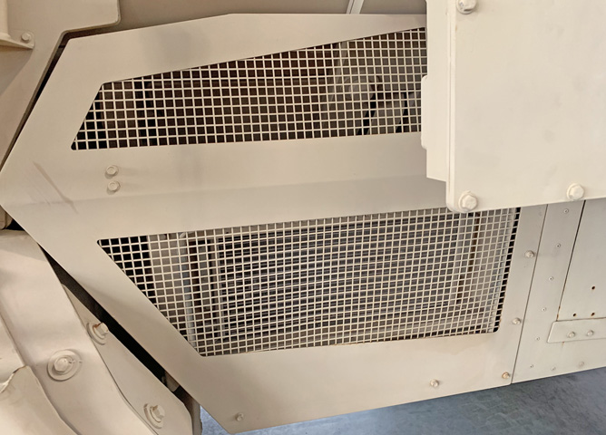
The air conditioner condenser could be found behind the screen on the driver's side.
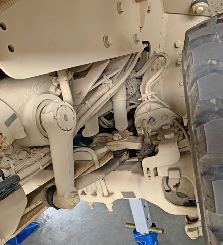
The front left suspension and steering assemblies are seen from the front.
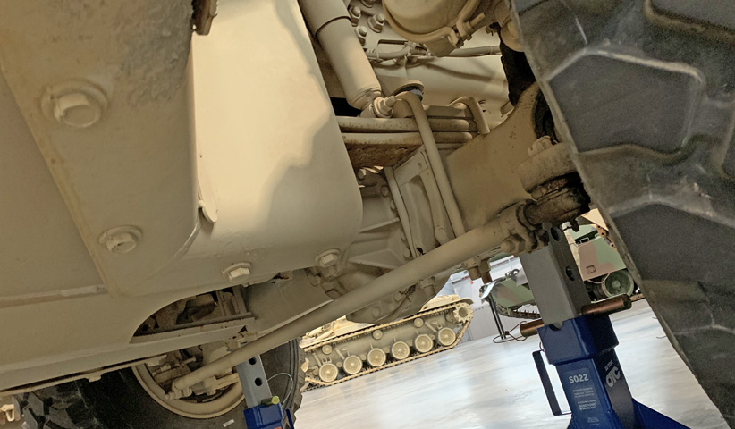
The front right suspension is shown from behind. The tie rod is visible under the axle, and the right front air brake chamber can just be seen at the top of the image. A shock absorber is to the left of the air brake chamber.
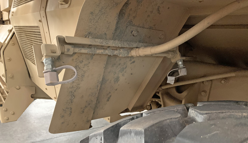
The fire extinguisher nozzles for the front tires were moved from their original location at the front of the wheel well to the rear face of the front bumper.
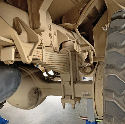
The right rear suspension is illustrated from behind in this image. The leaf springs sit on a rubber mount, and a rubber bump stop secures them from above. The upward slope of the hull is visible above the chassis frame, and the brake drum is large enough for dual wheels to be installed. The black engine exhaust muffler is at the left of the image.
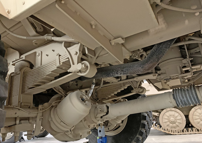
The right rear suspension is shown from the opposite angle. The propeller shaft can be seen attaching to the rear axle, and the rear brake chambers are mounted on the front of the rear axle, inset to allow room for dual rear wheels. The dark engine exhaust pipe makes its way rearward above the axle.
The fire extinguisher nozzles for the rear tires were mounted in the wheel wells ahead of the wheels.
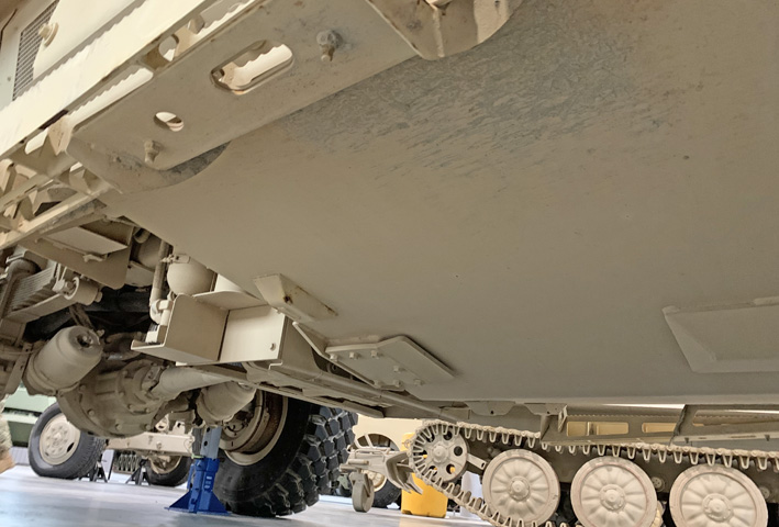
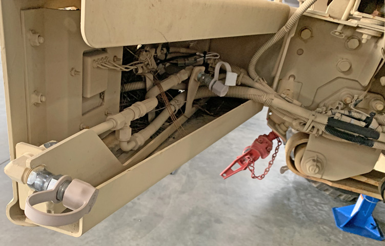
The engine was protected from below by sloping armor plates. Directly behind the engine, the transfer case was protected by a more rectangular enclosure that was open at the bottom. The rear propeller shaft, axle, and air brake chambers are in the background.
The fire extinguisher mounted to the right side of the transfer case enclosure is highlighted in this picture.
The winch installation in the front bumper is seen from behind.
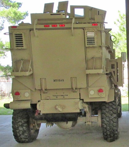
An armored window was placed on each side of the rear ramp, and the bottom step of ramp itself looped over the roof when closed. The black muffler can be seen behind the tow pintle, and the engine exhaust pipe exits to the left under a guard. More details of the MEAP kit and how it is mounted can be seen.
