Light Tank M22 Locust at the US Army Ordnance Museum.
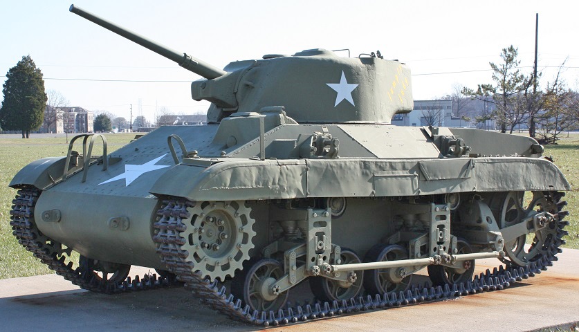
The suspension strengthening braces on the little M22 Locust are easily visible in this view, as is the driver's hood with sloping sides on the left side of the hull. The ends of the suspension braces were equipped with either a right- or left-hand thread that allowed the brace to be lengthened or shortened in order to align the road wheels and trailing idler. This tank has the driver's vision port, which is closed by a steel plug. The top of his periscope housing can be seen on the top of the hood. Above the sandshields are two of the lifting brackets that allowed the hull to be suspended under the belly of the C-54 Skymaster cargo plane. The sandshields themselves are a late design; early models descended further to the front and rear. Near the center of the sandshield is a hinged track inspection door that allowed the track tension to be measured. Proper tension allowed the track to sag 1.5-2.25" (3.8-5.72cm) at the inspection door. The trailing idler is stuck in an inclined position. (Photo by Richard S. Eshleman.)
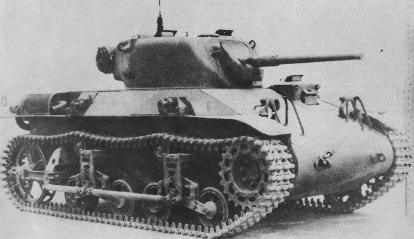
This is an early tank with the driver's direct vision slot and hood with vertical sides. The driver's periscope is raised on this vehicle, and the engine's muffler can be seen on the rear fender. (Picture from Development of Armored Vehicles, volume 1: Tanks.)
This rear view shows the location of the engine access door and the arrangement of the exhaust piping, which is damaged on this tank. (Picture courtesy 8Hussar Ottawa.)
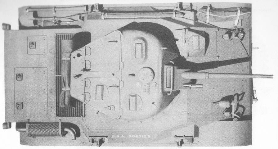
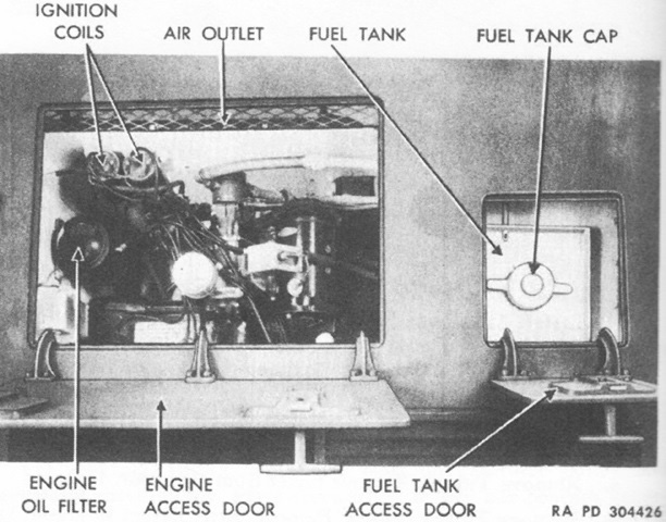
The crew's doors in the turret and hull can be seen here; the commander's door had a rotatable periscope in addition to the rotatable periscope to his front. The gunner had a fixed sighting periscope to his front. Between the forward turret periscopes was a ventilator. A ventilator with a reversible fan was installed starting with the seventy-seventh tank manufactured. The small door on the rear deck was for access to the fuel filler, while the larger door allowed access to the engine oil filter and ignition coils. (Picture from TM 9-724 Light Tank T9E1.)
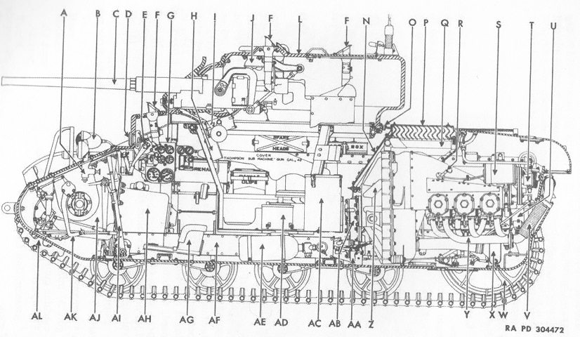
A cross-section of the vehicle is shown here. A. Head light socket and release. B. Siren. C. 37 mm. gun. D. Lookout hole plug. E. Driver's head cover mechanism. F. Periscope. G. Instrument panel. H. Turret basket phone box. I. Gun elevating mechanism. J. Ventilating fan. L. Turret hatch door. N. Bulkhead. O. Turret race. P. Air inlet screen and louvers. Q. Differential oil cooler. R. Engine oil level gauge. S. Generator. T. Differential oil pump. U. Starter. V. Exhaust pipe. W. Trailing idler wheel. X. Engine oil cooler. Y. Exhaust manifold. Z. Clutch housing. AA. Throttle slave cylinder. AB. Transfer case. AC. 37 mm. ammunition box. AD. Slip ring. AE. Fire extinguisher cylinder. AF. Heater air duct. AG. Driver's seat. AH. Transmission. AI. Steering brake levers. AJ. Controlled differential. AK. Clutch pedal. AL. Driving sprocket. (Picture from TM 9-724 Light Tank T9E1.)
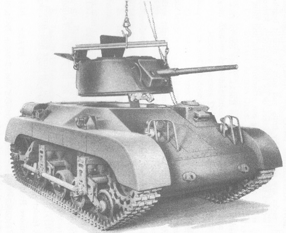
The turret is shown being lifted free of the hull, which was necessary to transport the tank via the C-54 Skymaster cargo plane. The later C-82 Packet aircraft and Britain's Hamilcar glider could carry the tank fully-assembled. This tank is fitted with the earlier sandshields. (Picture from TM 9-724 Light Tank T9E1.)
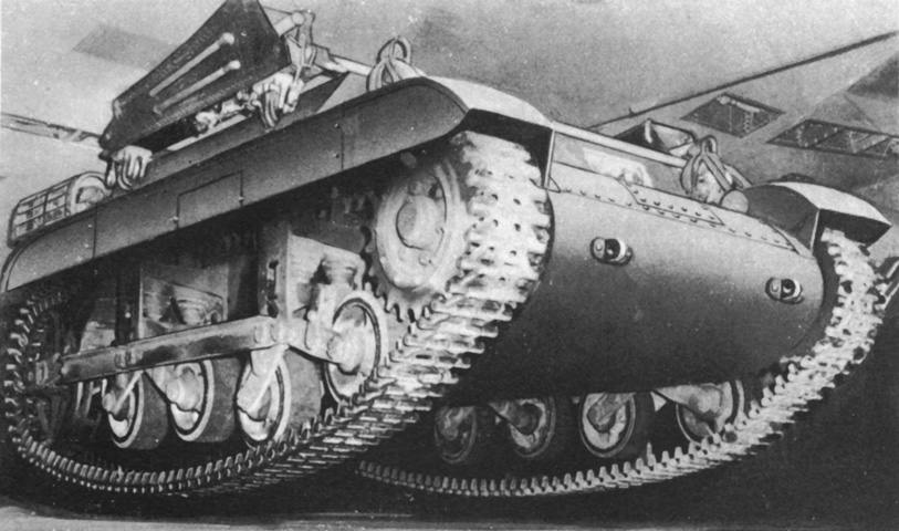
The hull is seen here slung beneath an aircraft after the turret has been removed. (Picture from Catalogue of Standard Ordnance Items, second edition 1944, volume I: Tank and Automotive.)
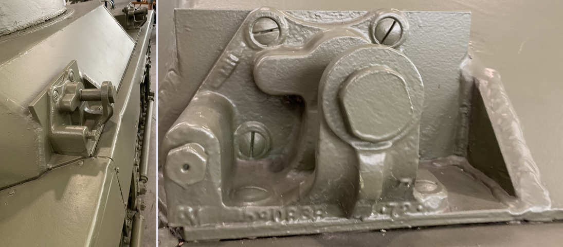
The right rear lifting bracket is shown from behind and the side.
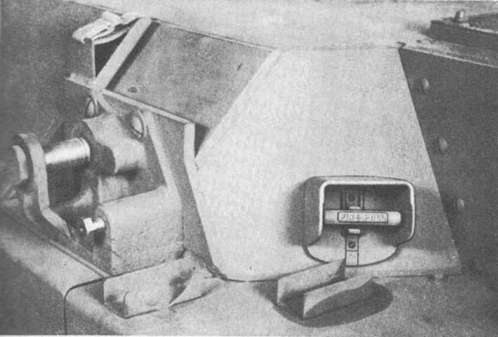
The left rear lift bracket is highlighted here from behind. The external control for the fixed fire extinguisher is also visible. (Picture from TM 9-724 Light Tank T9E1.)
A driver's hood with the direct vision slot was found on the first twenty-seven tanks produced. (Picture from TM 9-724 Light Tank T9E1.)
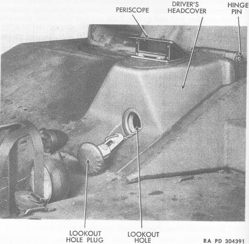
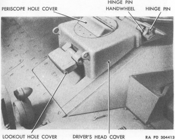
The later driver's hood with the lookout hole is shown here. In addition to the headcover, the driver was also provided with an escape hatch in the hull floor at the right-front of the turret basket. The driver's headcover was controlled by a crank handle mounted to the right of the headcover; rotating the handle to the right raised the headcover, and turning the handle to the left lowered it. (Picture from TM 9-724 Light Tank T9E1.)
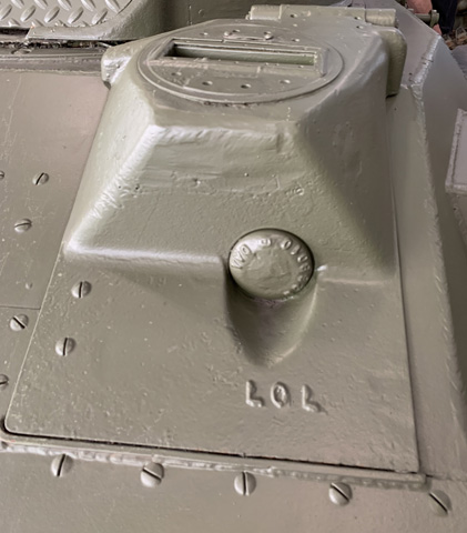
The lookout hole plug is sealed on this tank, and the taper of the driver's headcover is more easily seen from the front. Note that no gun mount is present, and the turret face is instead sealed with diamond plate.
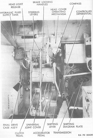
The driver's controls are illustrated in this image. A second compass was installed in the turret to the commander's right. (Picture from TM 9-724 Light Tank T9E1.)
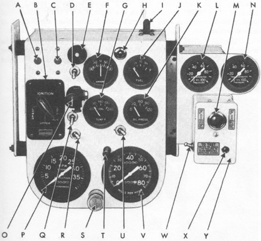
The driver's instrument cluster is labeled. A. Circuit breaker reset button (head light). B. Ignition switch. C. Circuit breaker reset button (instruments). D. Blackout light switch. E. Siren button. F. Ammeter. G. Engine oil temperature gage. H. Low oil pressure signal light (red). I. Master switch. J. Fuel gage. K. Engine oil pressure gage. L. Differential oil pressure gage. M. Fire detector signal light (red). N. Transmission oil pressure gage. O. Master light switch. P. Tachometer. Q. Detent switch. R. Starter switch. S. Primer. T. Speedometer reset button. U. Instrument panel light switch. V. Speedometer. W. Fire detector check light switch. X. Fire detector check light. Y. Fire detector control box. (Picture from TM 9-724 Light Tank T9E1.)
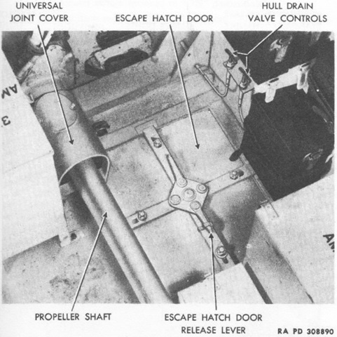
The floor escape hatch at the hull front right, opposite the driver, is shown in this picture. (Picture from TM 9-724 Light Tank T9E1.)
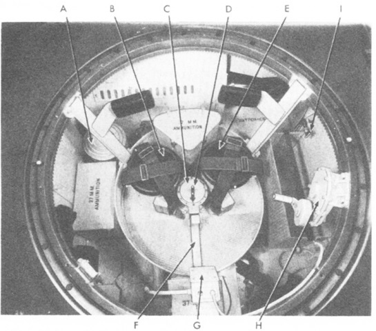
This image is looking down into the turret basket, with the front of the hull at the bottom. The directional arrow on the slip ring always pointed to the hull front, helping to orient the turret crew. Th floor escape hatch can be seen at the bottom left. A. Air cleaner. B. Loader's seat. C. Slip ring. D. Directional arrow. E. Gunner's seat. F. Conduit tunnel. G. Turret basket phone box. H. Traversing mechanism. I. Fire extinguisher--inside control. (Picture from TM 9-724 Light Tank T9E1.)
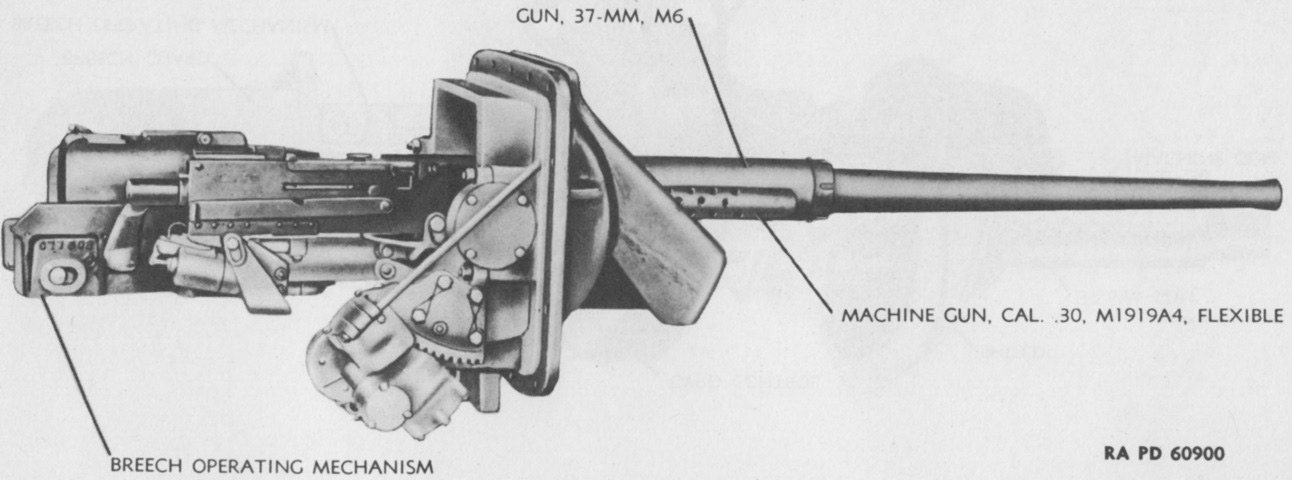
The right side of the combination gun mount is labeled in this picture. (Picture from TM 9-250 37-mm Gun M6, Mounted in Combat Vehicles.)
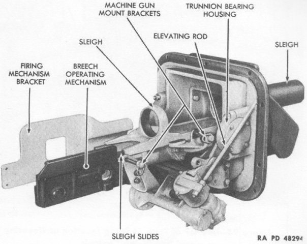
The right rear of the gun mount is detailed with the weapons absent. (Picture from TM 9-724 Light Tank T9E1.)
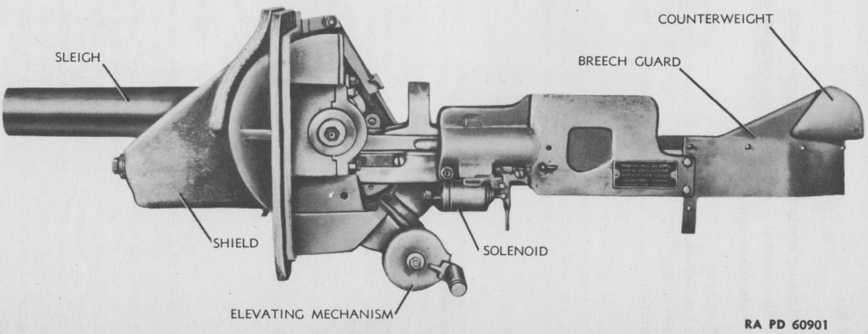
The opposite side of the gun mount is shown. (Picture from TM 9-250 37-mm Gun M6, Mounted in Combat Vehicles.)
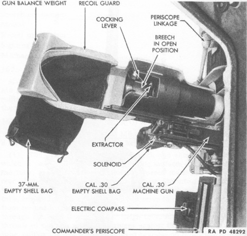
The breech of the 37mm gun is open in this top-down view. (Picture from TM 9-724 Light Tank T9E1.)
The turret interior is shown here from the commander's side with the gun mount installed. (Picture from TM 9-724 Light Tank T9E1.)
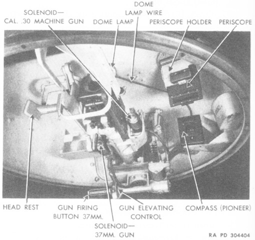
The breech of the 37mm gun is detailed in this picture. The manual turret traverse control was to the left of this frame. Contrary to the labeling of this image, the 37mm gun was fired by the button located on the elevation handwheel, while the .30cal machine gun was fired by a similar button on the turret traverse handwheel.
The gunner's periscope M8A1 was an improvement over the M8 in that it was able to use illumination. Compared to the periscope M4A1 found in the light tank M5A1, the M8A1 was a bit longer (14¾" x 6½" x 1¾" [34.47cm x 17cm x 4.45cm] versus the M4A1's 11-1/16" x 6½" x 1¾" [28.0988cm x 17cm x 4.45cm]) and featured two knobs to lock it into the periscope holder. The 1.8x telescope M46A2 used the same reticle as the M5A1's 1.44x M40A2, but differed slightly dimensionally. The M46A2 was 8⅞" (22.54cm) long, with a 1-1/16" (2.6988cm) diameter objective end, 0.875" (2.22cm) diameter eyepiece end, and a 6° field of view. The M40A2 was 5-17/64" (13.37469cm) long, with an objective end diameter of 1¼" (3.18cm), eyepiece end diameter of 0.75" (1.9cm), and a 9° field of view. (Picture from TM 9-724 Light Tank T9E1.)
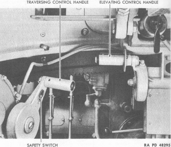
The spatial relationship between the gunner's elevating and traverse controls is illustrated in this view. (Picture from TM 9-724 Light Tank T9E1.)
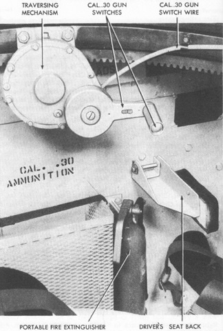
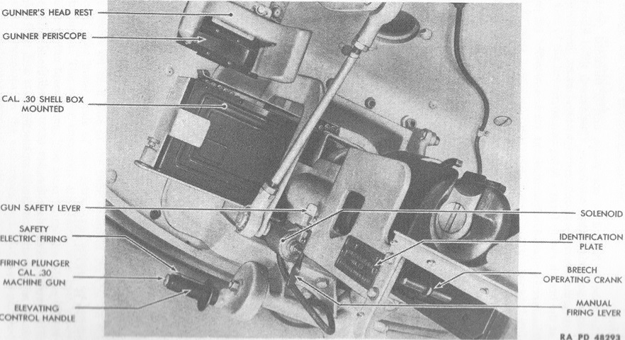
A closer look at the traversing mechanism is provided here. The electric switch on the side of the hand crank acted as a safety for the machine gun, while the firing switch was at the end of the handle, operable with the gunner's thumb. A portable fire extinguisher was clamped to the hull behind the driver's seat, and--although absent here--a spare machine gun barrel could be stowed to the front of the .30cal ammunition basket. (Picture from TM 9-724 Light Tank T9E1.)
The right side of the hull is shown with the turret removed. The turret basket is installed, and the two closely-situated crew seats are visible. (Picture from TM 9-724 Light Tank T9E1.)
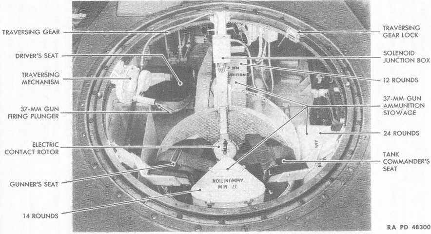
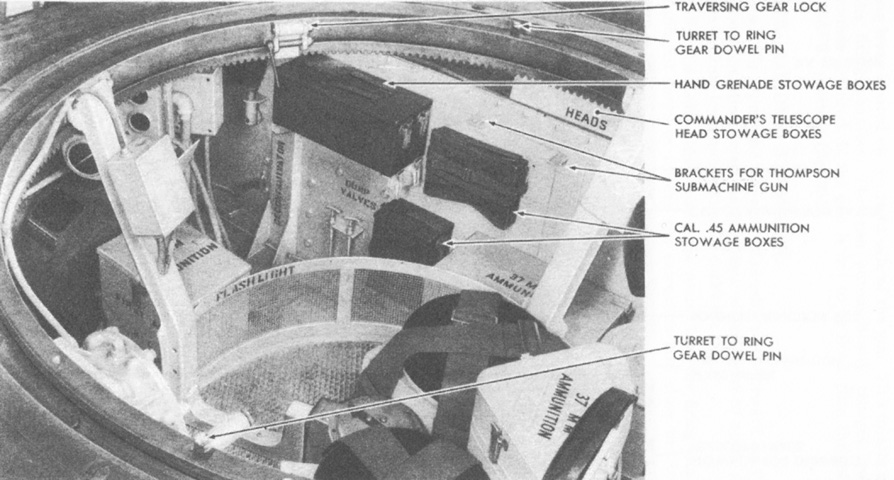
Ammunition for the 37mm gun was stowed in three boxes in the fighting compartment. The prescribed loadout was 30% high-explosive, 60% armor-piercing, and 10% canister. (Picture from TM 9-724 Light Tank T9E1.)
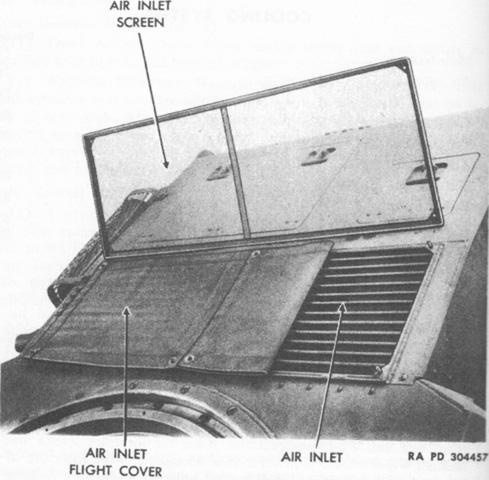
The air inlet in the rear deck behind the turret was protected by a screen. When starting the engine in low temperatures, a cover could be placed over part or all of the inlet to facilitate warming up the engine. When the tank was being transported by plane, the inlet was to be totally covered. (Picture from TM 9-724 Light Tank T9E1.)
The rear deck access doors are opened in this image. (Picture from TM 9-724 Light Tank T9E1.)
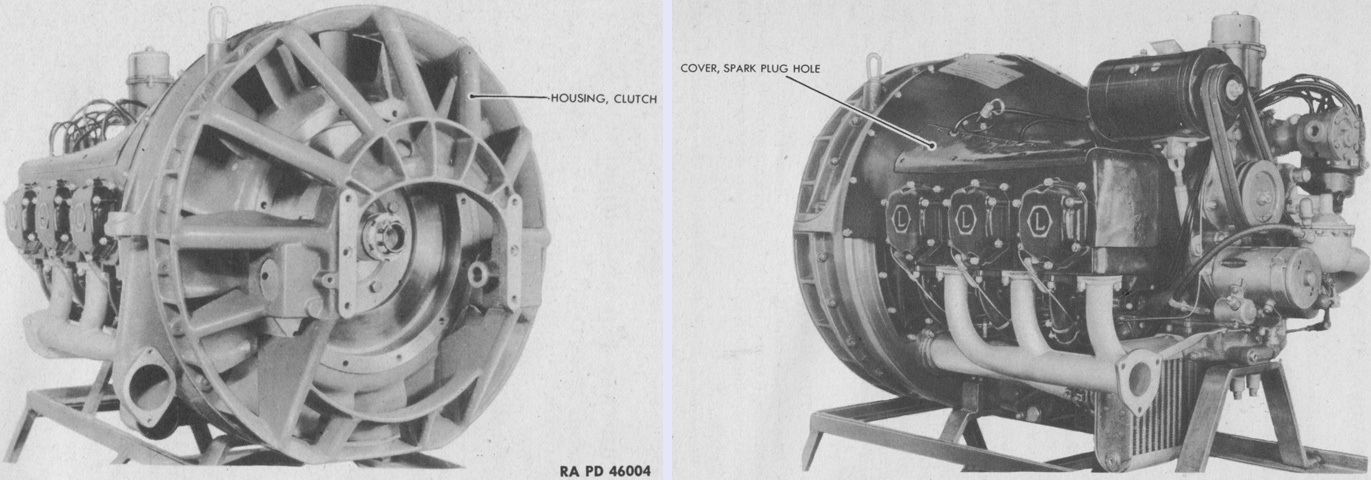
The direct-drive O-435T engine, seen from the front right and left rear respectively, was adapted from aircraft. Changes made to prepare it for tank use included replacing the magnetos with a distributor, adding a generator, and using an enlarged finned flywheel that doubled as a cooling fan. The large clutch flywheel was enclosed in a skeletonized housing. The flywheel end of the engine was considered the front, and right and left were determined by looking at the rear of the engine. (Picture from TM 9-1724A Ordnance Maintenance--Engine and Engine Accessories for Light Tank T9E1.)
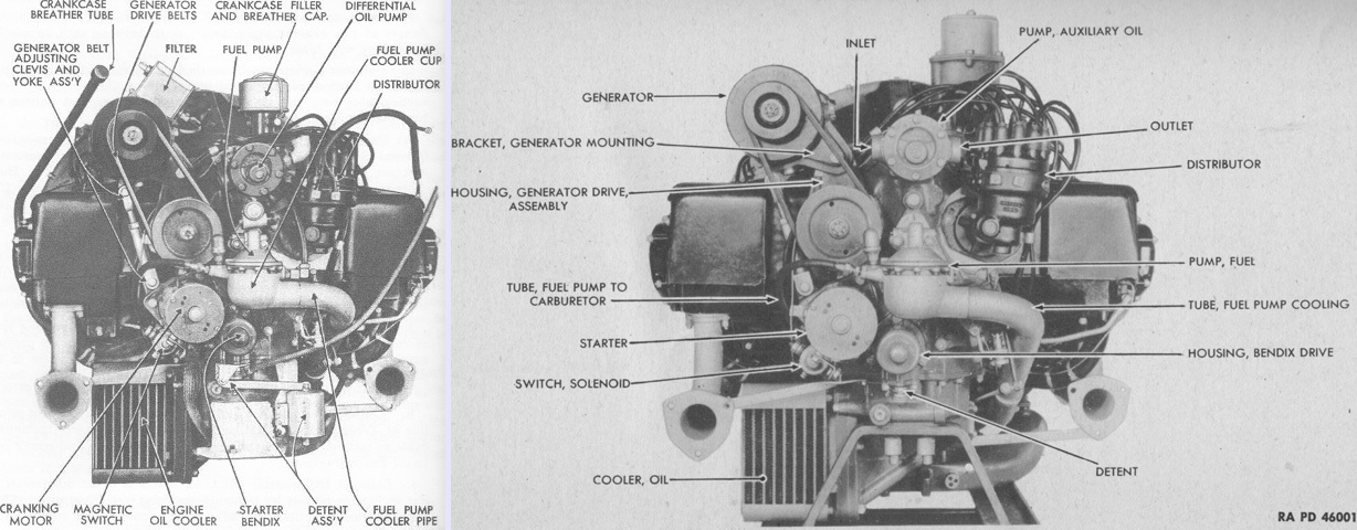
Two views of the engine's rear are labeled. It displaced 434in³ (7110cm³) with a 4⅞" (12.38cm) bore and a 3⅞" (9.843cm) stroke. It had a 6.25:1 compression ratio and weighed 755lb (342kg) dry. Overall height, width, and length were 31.28" (79.45cm), 35.62" (90.47cm), and 48.07" (122.1cm), respectively. (Picture from TM 9-724 Light Tank T9E1 and TM 9-1724A Ordnance Maintenance--Engine and Engine Accessories for Light Tank T9E1.)
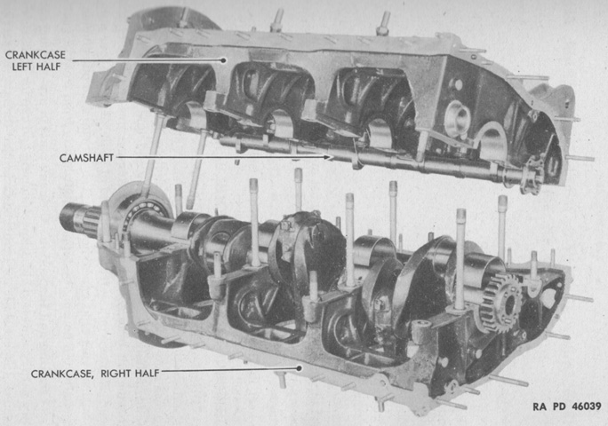
The crankcase assembly was composed of two ribbed aluminum castings separated vertically along the centerline and secured by studs and nuts. Each connecting rod operated on a separate throw of the crankshaft, so the cylinders were slightly staggered. The cylinders were numbered front to rear 1-3-5 on the right and 2-4-6 on the left. (Picture from TM 9-1724A Ordnance Maintenance--Engine and Engine Accessories for Light Tank T9E1.)
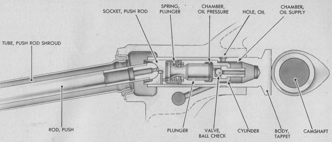
The valves were actuated by mushroom-type hydraulic tappets. The tappets were zero-clearance hydraulic lifters that provided a column of oil between toe cam and push rod, which bore the load while the valve was off its seat. The oil column's length was automatically adjusted every revolution of the camshaft to give zero clearance regardless of engine temperature. The oil supply chamber remained full when the engine was turned off, so the next time the engine was operated the tappet adjustment occurred when the engine starter was used. The lifter would not hold the valve open when it was supposed to be closed during normal running. The push rods were hollow and carried oil from the tappet to the valve rocker. (Picture from TM 9-1724A Ordnance Maintenance--Engine and Engine Accessories for Light Tank T9E1.)
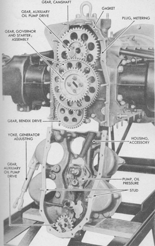
The accessory housing, shown here being removed, was an aluminum-alloy casting attached to the rear of the main crankcase by studs and nuts, and the housing also formed the bearing for some accessory drives. The starter was separate from and geared to the Bendix drive; the fuel pump was operated by a plunger driven by a cam in the tachometer drive shaft; the oil pressure pump was an integral part of the accessory housing; and the auxiliary oil pump on the upper part of the housing was driven by a gear assembled to the camshaft gear. (Picture from TM 9-1724A Ordnance Maintenance--Engine and Engine Accessories for Light Tank T9E1.)
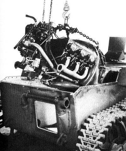
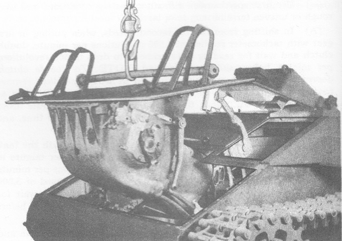
The engine is being removed from the tank in this picture; prerequisites included removing the turret and rear deck armor. (Picture from TM 9-724 Light Tank T9E1.)
The transmission and controlled differential are being removed. The assembly was attached to the hull front plate by sixteen bolts. (Picture from TM 9-724 Light Tank T9E1.)
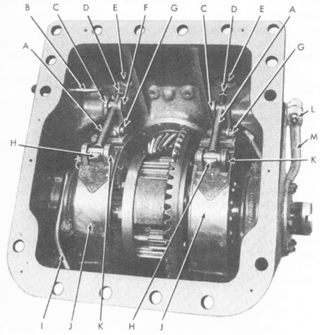
The interior of the controlled differential is shown here. A. Adjusting rod spring. B. Oil tube. C. Steering band cam and shafts. D. Adjusting nuts. E. Adjusting holes. F. Adjusting rod cam pin. G. Steering band link pin. H. Adjusting rod block. I. Oil tube. J. Steering brake bands. K. Adjusting rod band pin. L. Steering arm clamp bolt. M. Steering lever arm. (Picture from TM 9-724 Light Tank T9E1.)
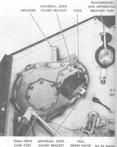
From the controlled differential, the power to the tracks was routed through the final drive case assembly on each side of the hull. These contained a pinion and drive gear mounted on ball bearings. Connected via splined shafts were the drive sprockets. (Picture from TM 9-724 Light Tank T9E1.)
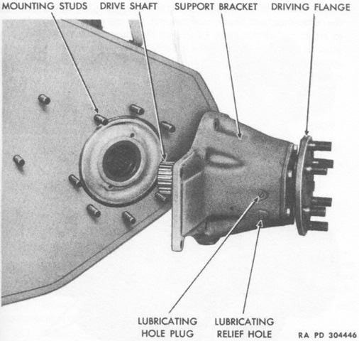
The right-side drive shaft support bracket assembly is shown dismounted. (Picture from TM 9-724 Light Tank T9E1.)
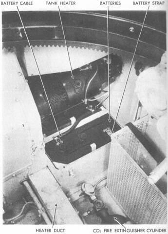
Two 6-volt batteries were wired in series to supply 12-volt current. Battery capacity was 204 ampere-hours at a 20-hour rate. The batteries were housed in the hull floor at the left rear of the fighting compartment. (Picture from TM 9-724 Light Tank T9E1.)
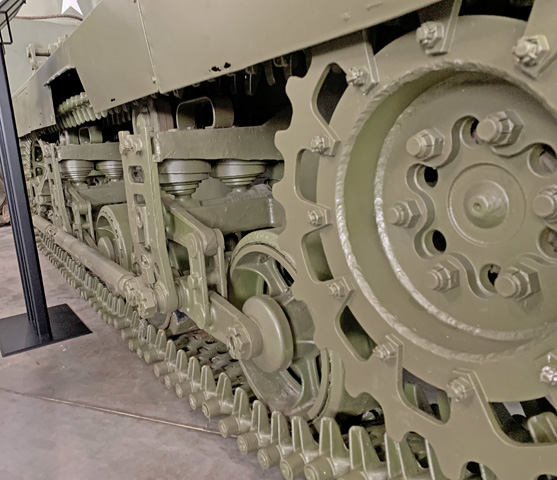
This low angle reveals the volute springs and track skid of the suspension bogie, and a return roller is visible behind the bogie. The hinged track tension inspection door in the sandshield is absent.
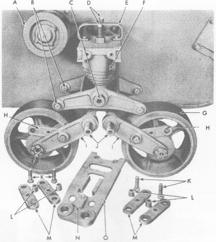
The suspension has been partially disassembled in this image. A. Track support roller. B. Rocker arms. C. Rocker arm shaft. D. Spring compressing studs. E. Track skid. F. Volute spring. G. Bogie wheel. H. Arm links. I. Bogie wheel arms. J. Bogie wheel arm shaft. K. Link bolts. L. Link spacers. M. Arm links. N. Flight block. O. Bogie face plate. (Picture from TM 9-724 Light Tank T9E1.)
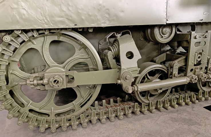
The trailing idler wheel featured a similar adjustment scheme as the light tanks M3 and M5: the large plate adjusting nuts were loosened until the serrations in the trailing wheel arm and adjusting plates were freed, then the track adjusting nuts were used to move the plates the same number of serrations, after which the plate adjusting nuts were again tightened. The idler wheel's volute spring can be seen, as well as the jam nuts and adjustment points on the suspension braces.
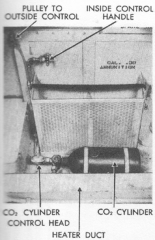
The fixed fire extinguisher was used to combat fires in the engine compartment. (Picture from TM 9-724 Light Tank T9E1.)
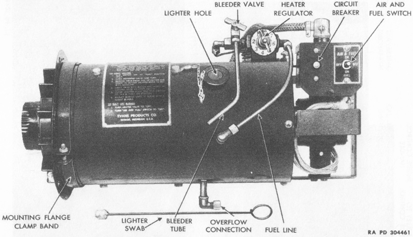
A gasoline-fueled heater could be used to warm the engine compartment, differential oil lines, and operating compartment. The heater's exhaust gases were ducted to the engine compartment, while heat from the outer cells of the unit could be deflected via a damper into the engine compartment or through ducts following the differential oil lines to the transmission case in the fighting compartment. To light the heater, the switch was flipped to the FUEL position, the metering valve was opened by one turn, and the swab was inserted into the lighter door to be dampened with gasoline. The swab was then lit with a match and reinserted into the lighter door. The switch was then flipped to the AIR & FUEL position, and the burner was adjusted until the heater operated with a slight rumble. (Picture from TM 9-724 Light Tank T9E1.)
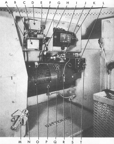
The heater is shown installed. A. Terminal 9A to filter. B. FL 12 filter--bottom. C. Wire--to generator field terminal. D. FL 12 filter--top. E. Wire to regulator field terminal. F. FL 13 filter. G. Terminal 1A to trouble lamp socket. H. Trouble lamp socket. I. Bleeder valve. J. Fuel control. K. Current and voltage regulator. L. Circuit breaker. M. Heater air duct damper lock nut. N. Heater air duct (valve) damper. O. Swab. P. Heater. Q. Lighting tube window. R. Fuel line. S. Overflow line. T. Control switch. (Picture from TM 9-724 Light Tank T9E1.)
