Medium Tank M26 Pershing.
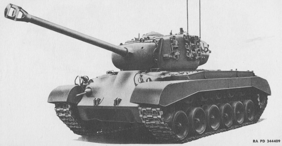
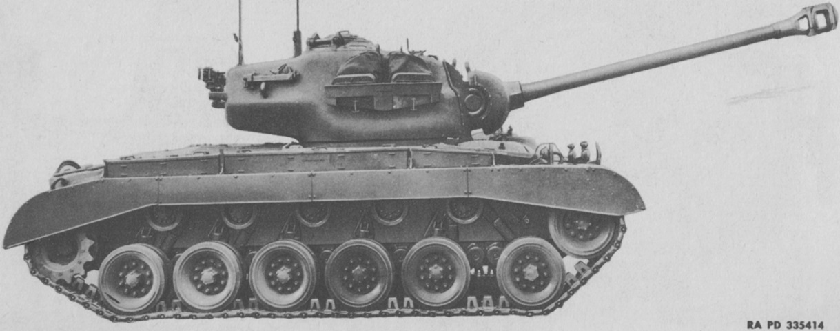
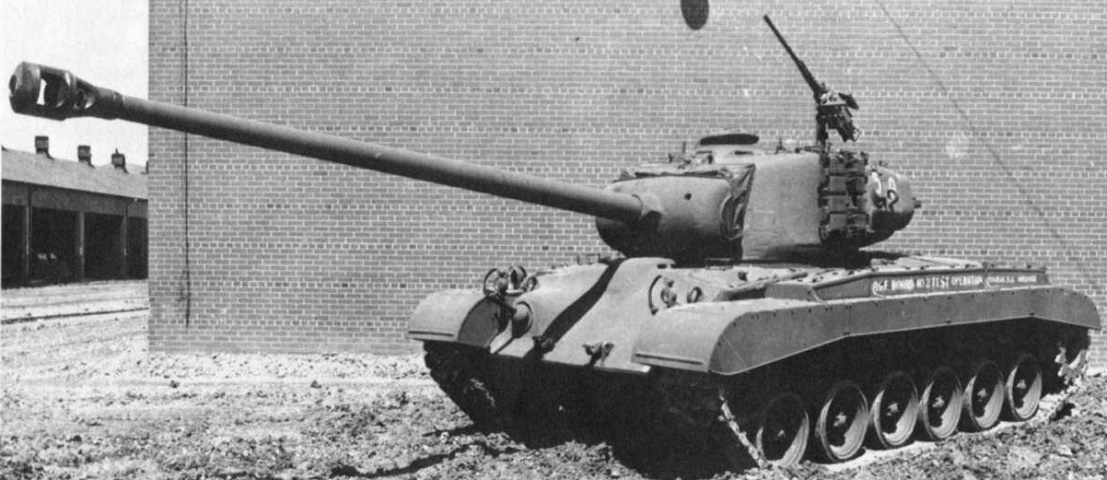
The first T26E3s were accepted just over two and a half years after the first M4A1 Shermans, but the Pershing appears thoroughly more modern thanks to its long gun tube, torsion bar suspension, and wider stance. The 90mm gun M3 was fitted with a large muzzle brake, contrasting with the smaller single-baffle muzzle brake on the M26A1 Pershing and M46 Patton. Note the stowage of spare track links on the turret sides. (Picture from TM 9-735 Heavy Tank T26E3.)
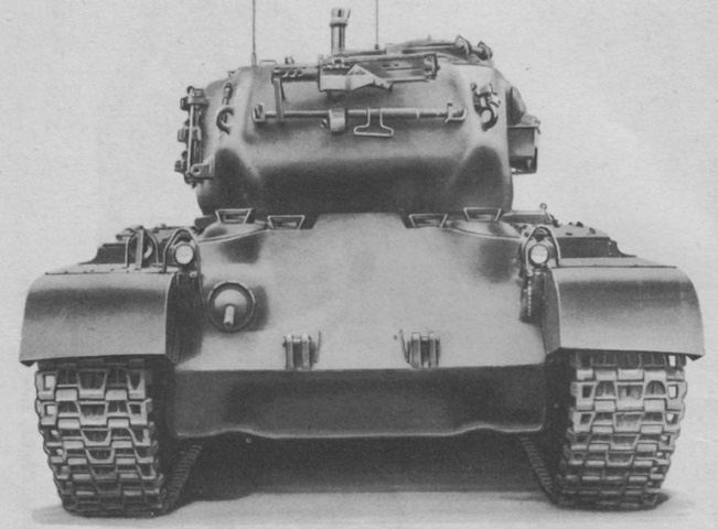
The turret is reversed and the main gun is stowed in the travel lock. The drivers were provided with a periscope mount in the hatch door above their position as well as a second periscope inboard of their doors. The .50cal machine gun and barrel are stowed on the turret rear. (Picture from TM 9-735 Heavy Tank T26E3.)
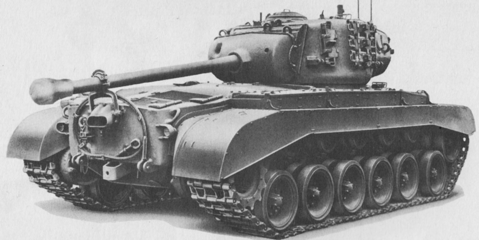
This rear view of the M26 Pershing differentiates it from the M46 Patton. M26's engine exhaust was vented through the port in the upper rear plate, and M26 lacked the transmission access plates that M46 featured in its rear hull plate. The arrangement of the main gun travel lock on the exhaust port can be seen, as well as the stowage of a towing cable on the hull rear. When not in use, the travel lock could be swung down to below the exhaust port. (Picture from TM 9-735 Heavy Tank T26E3.)
The drive sprocket of the M26 is noticeably lower than that of later related tanks like the M46. Foul weather hoods for the drivers' hatches are stowed on the turret side. (Picture from TM 9-735 Heavy Tank T26E3.)
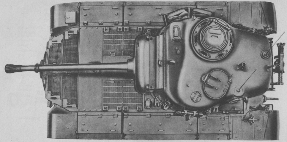
The complex shape of the turret can be seen in this top-down view. The gunner was provided with a periscope in front of the commander's cupola, and the loader had a rotating periscope in front of his hatch. The inconvenience of the .50cal machine gun mount location between and behind the turret hatches is obvious. Stowage boxes line both fenders. The grille doors at the very rear of the hull are the air exhaust doors, while the grilles just aft of the turret are the air intake doors. The guard for the right-hand fuel filler can also be seen just to the gun shield's left. (Picture from TM 9-735 Heavy Tank T26E3.)
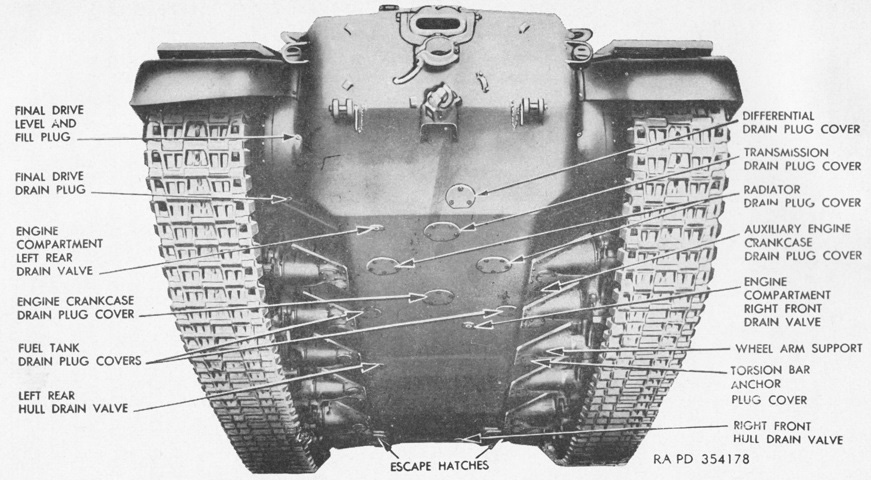
Drain plugs, drivers' escape hatches, and other features of the hull underside are labeled here. The hull weighed ~15 tons (~14,000kg). (Picture from TM 9-735 Medium Tanks M26 and M45.)
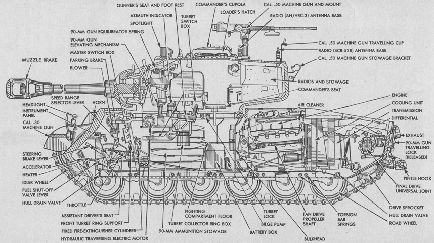
A cross-section of the tank is drawn here. The .50cal MG pedestal folded to the rear when stowed. (Picture from TM 9-735 Heavy Tank T26E3.)
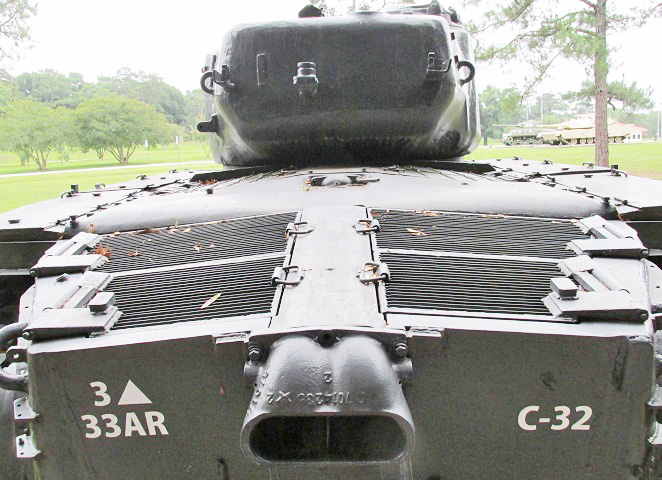
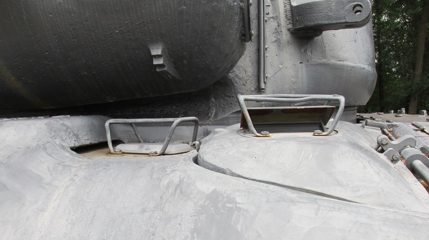
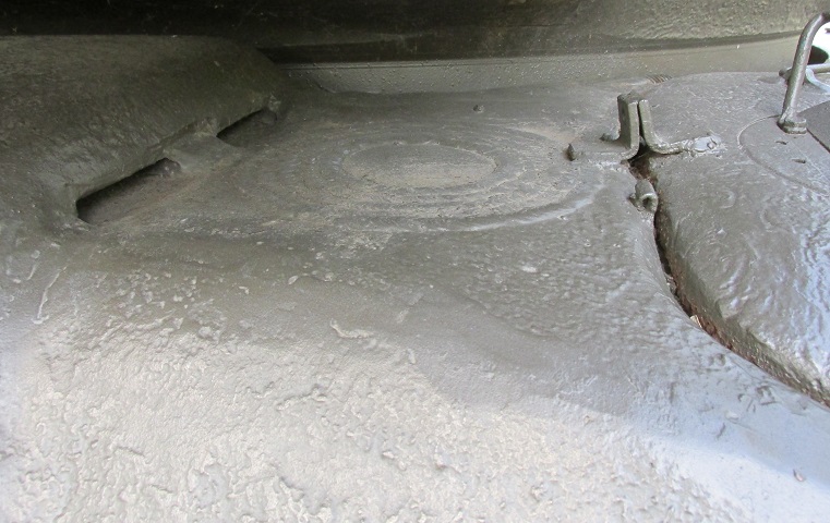
A closer view of the engine exhaust port and rear deck is provided here. The gun travel lock is not mounted, and the cover for the coolant filler cap is visible in the center.
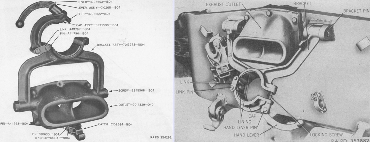
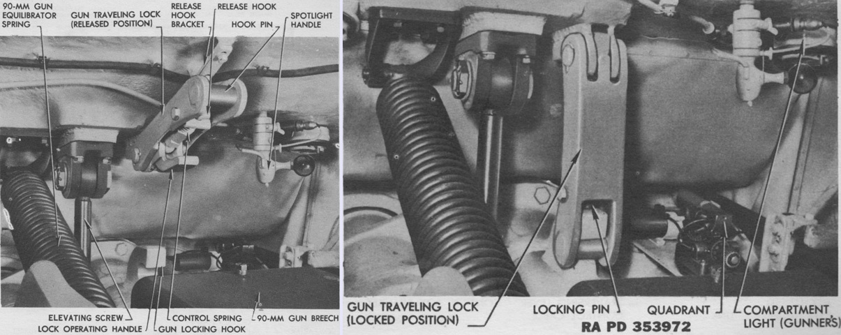
The initial gun travel lock is shown on the left; its bracket attached directly to the engine exhaust outlet. This design stressed the exhaust port, so the travel lock was changed to have the mounting brackets attached to the hull rear plate instead, as shown on the right. (Picture from ORD 9 SNL G-226 List of All Service Parts for Tank, Medium M26; Tank, Medium, M45 and TM 9-735 Medium Tanks M26 and M45.)
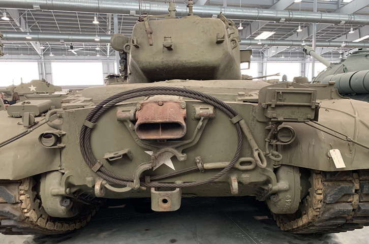
The travel lock is not centered around the exhaust tip on this tank. An infantry phone box has been mounted on the hull rear plate's upper right corner.
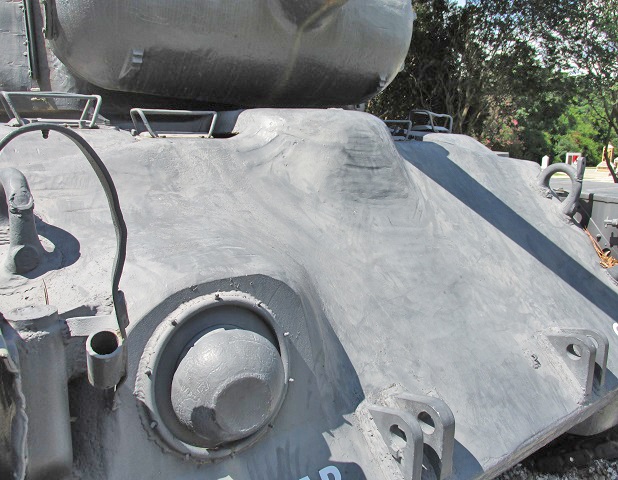
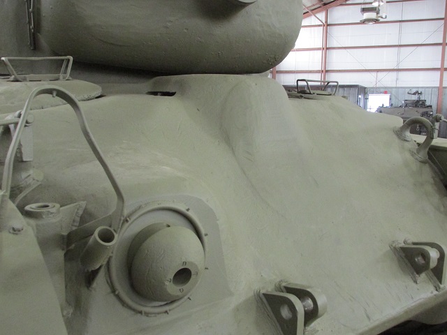
The driver's periscope arrangement and the opening for the central ventilator are highlighted here.
This picture provides an overview of the earlier upper front hull with two periscopes per driver and the 400cfm (11m³/min) ventilator.
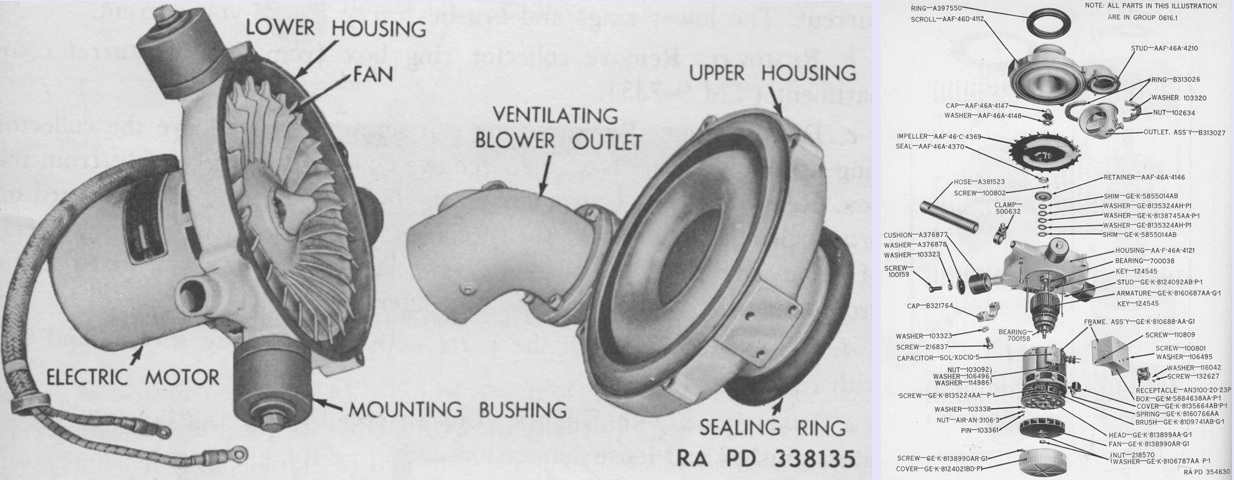
Partially-disassembled and exploded views of the early Rotoclone type hull ventilator are shown here on the left and right, respectively. (Pictures from TM 9-1735B Ordnance Maintenance--Medium Tanks M26 and M45 Tracks, Suspension, Hull and Turret and ORD 9 SNL G-226 List of All Service Parts for Tank, Medium M26; Tank, Medium, M45.)
This tank is fitted with the 1,000cfm (28m³/min) ventilator between the drivers, and the front hull casting can be contrasted with the earlier vehicle above. The extra periscopes for the drivers have been eliminated.
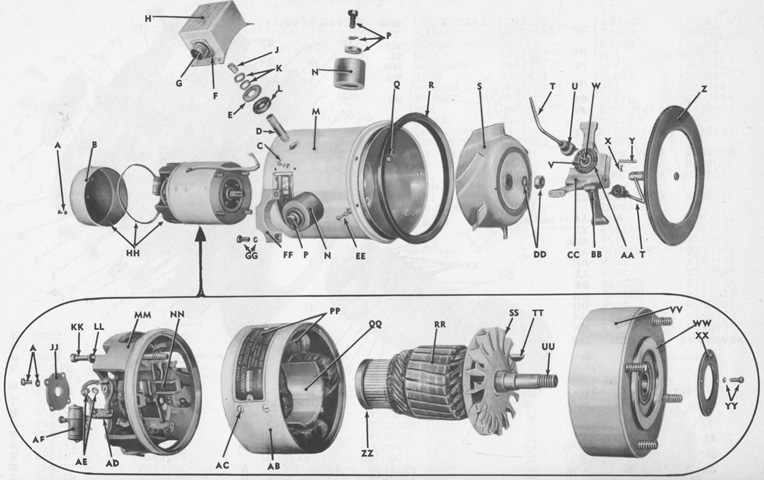
The later American Air Filter hull ventilator is seen disassembled. A. Screw; washer. B. Cover. C. Screw; washer. D. Nipple. E. Washer. F. Nut; screw; washer. G. Receptacle. H. Box, assembly. J. Bushing. K. Nut. L. Grommet. M. Case. N. Cushion. P. Screw; washer; washer. Q. Nut. R. Seal, assembly. S. Fan. T. Handle. U. Hub. V. Disc. W. Shaft. X. Screw; washer. Y. Rack. Z. Seal, assembly. AA. Screw; washer. BB. Screw. CC. Support, assembly. DD. Nut; washer. EE. Screw; washer. FF. Cap. GG. Screw; washer. HH. Motor, assembly. JJ. Retainer. KK. Bolt. LL. Washer. MM. Commutator, assembly. NN. Holder, assembly. PP. Coil, assembly. QQ. Shoe, assembly. RR. Armature, assembly. SS. Fan. TT. Key. UU. Shaft. VV. Head, assembly. WW. Bearing. XX. Retainer. YY. Screw; washer. ZZ. Ring. AB. Stator, assembly. AC. Screw; washer. AD. Brush. AE. Screw; washer. AF. Capacitor. (Picture from ORD 9 SNL G-226 List of All Service Parts for Tank, Medium M26; Tank, Medium, M45.)
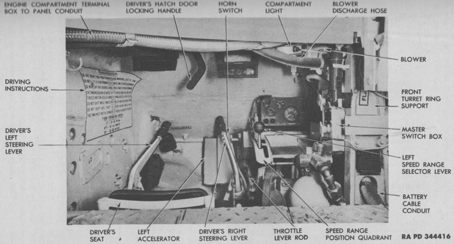
Details of the driver's position are illustrated here. (Picture from TM 9-735 Heavy Tank T26E3.)
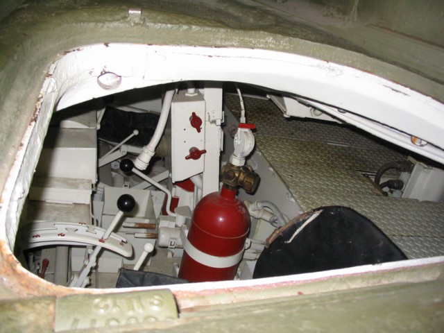
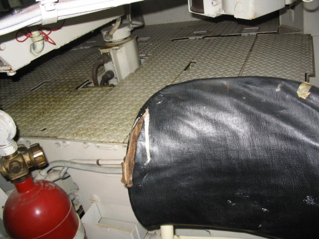
This view is peering into the open driver's hatch, and it provides us with a real-life counterpart of the above image. The fire extinguisher bottle is obvious, and behind this with the two red knobs is the master switch box. The white-tipped lever in front of the fire extinguisher is the left throttle lever, and in front of this is the left speed range selector in its gated quadrant. The white-tipped right throttle lever can be seen on the opposite side of the tank, and in the middle is the black-tipped parking brake lever.
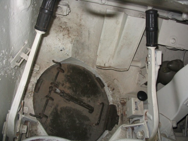
The bottom of the driver's position is shown here. The floor escape hatch contrasts with the white of the vehicle interior, and the large accelerator pedal can be seen to the front of the tank. The steering brake levers flank the driver's seat, and the black-tipped lever next to the escape hatch is the left fuel tank shut-off valve control lever.
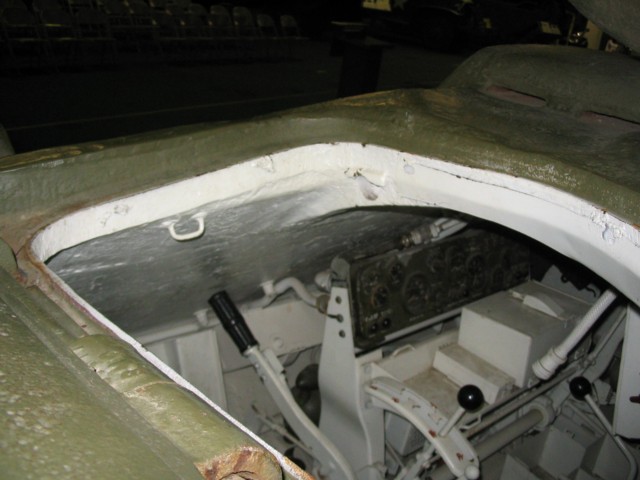
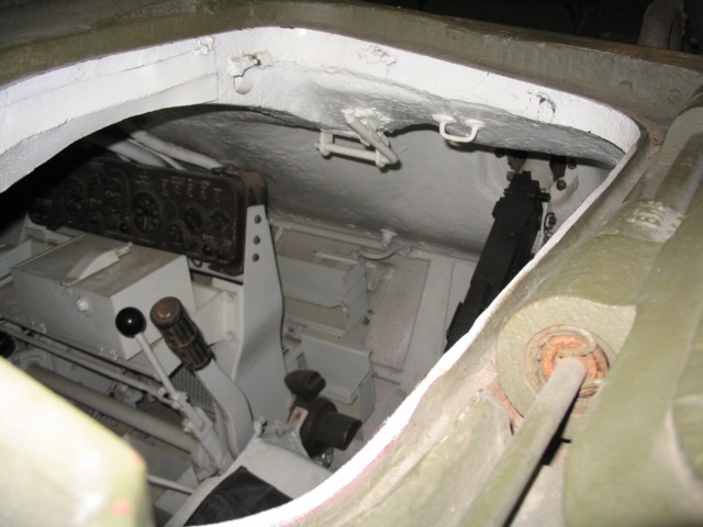
The position of the drivers' instrument panel can be seen in this image. The ventilator between the drivers can also be seen on the hull roof.
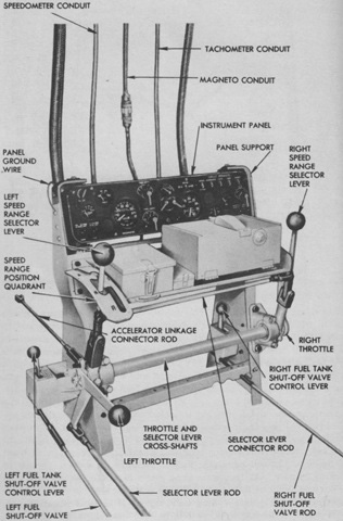
The instrument panel and controls are shown dismounted from the vehicle. (Picture from TM 9-735 Heavy Tank T26E3.)
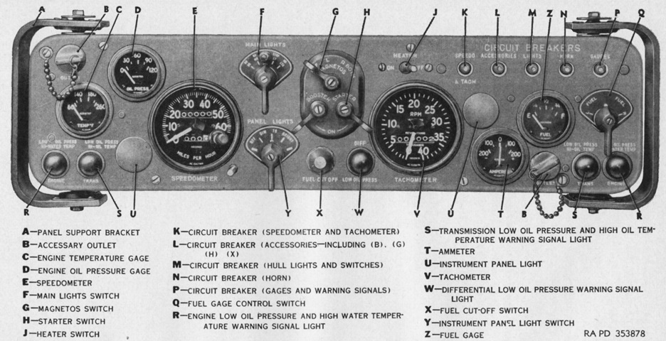
The instrument panel is detailed here. (Picture from TM 9-735 Medium Tanks M26 and M45.)
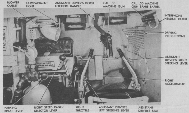
The assistant driver's position is shown here. Like all American tanks equipped with a bow machine gun, no sighting device was provided beyond his normal periscopes. (Picture from TM 9-735 Heavy Tank T26E3.)
The assistant driver was provided with a duplicate set of controls as well as the bow machine gun. The left steering brake lever and the speed range selector lever can be seen through the hatch. Unlike the driver's position, the accelerator pedal was under the assistant driver's left foot.
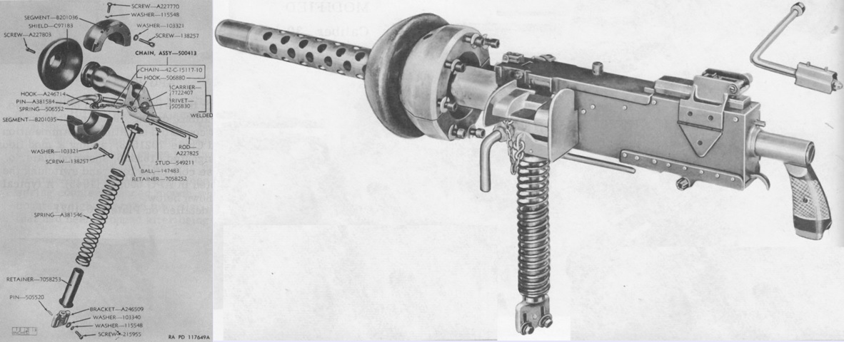
Exploded and assembled views of the .30 caliber ball mount 7722408 are shown on the left and right, respectively. The split ball housing was bolted to the hull, and the shield was in turn attached to this ball housing. An ammunition box M1 was secured in a bracket on the hull, and an ammunition feedway member helped guide the ammunition belt into the chamber. An expended link chute, expended case collection bag, travel lock, and equilibrator spring were all included. (Picture from Weapon Mounts for Secondary Armament.)
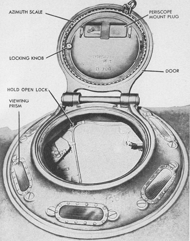
Details of the commander's cupola are visible in this picture. The cupola door was mounted on a ball bearing race composed of 61 balls of either 0.500" (1.27cm) or 0.437" (1.11cm) diameter that allowed the periscope to be rotated 360°. An azimuth scale was found on the outer edge of the cupola door. (Picture from TM 9-735 Medium Tanks M26 and M45.)
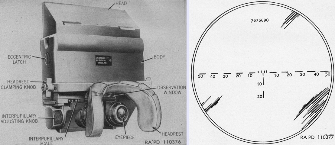
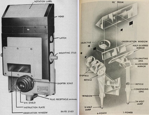
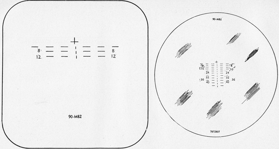
The periscope M15 could be mounted in the cupola rotor. This device had a 1x optical system for wide, close-in vision as well as a 7x telescope for distant viewing. The 1x system was used through an observation window, while the 7x system was provided with two eyepieces, allowing stereoscopic vision. The left-hand 7x eyepiece contained the reticle sketched on the right, graduated in mils for help in estimating lateral and vertical deflections. Field of view for the 1x system was 60° horizontal and 13°30' vertical, and 10° for the 7x telescope. (Picture from TM 9-735 Medium Tanks M26 and M45.)
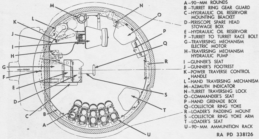
An overview of the turret interior (minus the gun mount) is sketched in this drawing. The turret weighed 7 tons (6,400kg) with the weapon installed. (Picture from TM 9-1735B Ordnance Maintenance--Medium Tanks M26 and M45 Tracks, Suspension, Hull and Turret.)
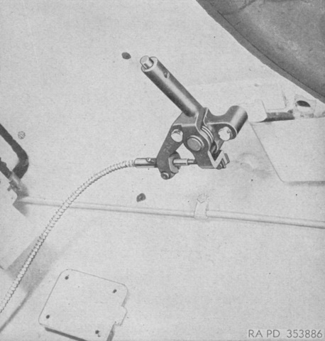
On the turret roof behind the gunner's seat, the tank commander was provided with a handle that could override the gunner's turret traverse inputs. To traverse the turret to the left, the commander would press the button on the end of the handle and push it forward; right traverse was accomplished by pulling it to the rear. (Picture from TM 9-735 Medium Tanks M26 and M45.)
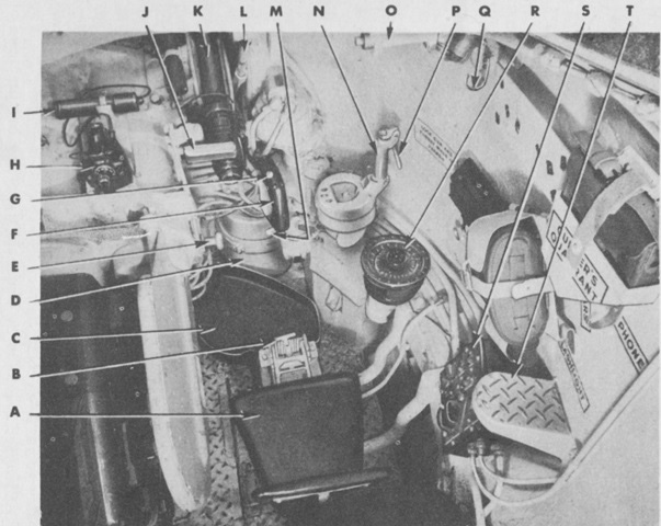
The gunner's controls are shown here. The gunner was provided with a trigger switch for the 90mm gun on the power traverse control handle as well as a foot firing switch. The legend is as follows: A. Gunner's seat. B. Seat adjusting handle. C. Gunner's platform. D. Air cleaner. E. Gun elevating wheel handle. F. Power traverse control handle with trigger-type switch. G. Cal. .30 coaxial machine gun firing button. H. Elevation quadrant M9. I. Battery container. J. Telescope headrest. K. Telescope M71C. L. Gunner's periscope synchronizing link. M. Traversing mechanism gearshift lever. N. Manual traversing handle. O. Commander's turret traversing lever. P. Brake release lever. Q. Gunner's interphone headset hook. R. Azimuth indicator. S. Turret switch box. T. Step. (Picture from TM 9-735 Heavy Tank T26E3.)
A lower angle is provided of the gunner's position. His seatback is not present for clarity. (Picture from TM 9-1735B Ordnance Maintenance--Medium Tanks M26 and M45 Tracks, Suspension, Hull and Turret.)
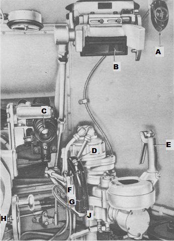
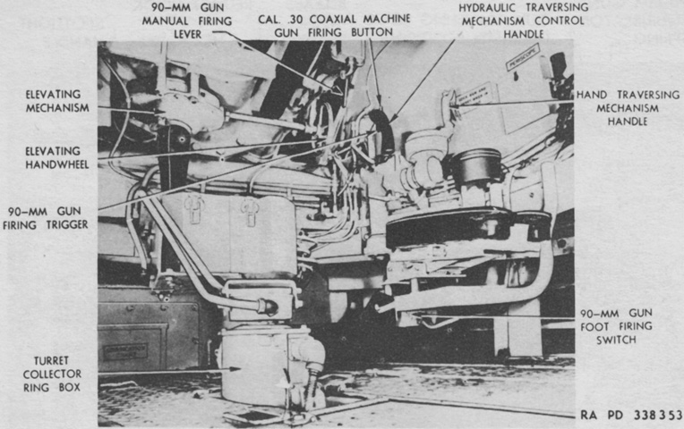
This view of the gunner's controls includes his sighting instruments. A linkage connected the periscope mount M73 to the gun mount so that the periscope moved in elevation along with the gun. A. Compass. B. Periscope. C. Direct sight telescope. D. Cal. .30 machine gun electrical firing trigger. E. Manual turret traverse control handle. F. 90-mm gun electrical firing trigger. G. Hydraulic turret traverse control handle. H. Elevating handwheel. J. Turret traverse gearshift lever. (Picture from TM 9-735 Heavy Tank T26E3.)
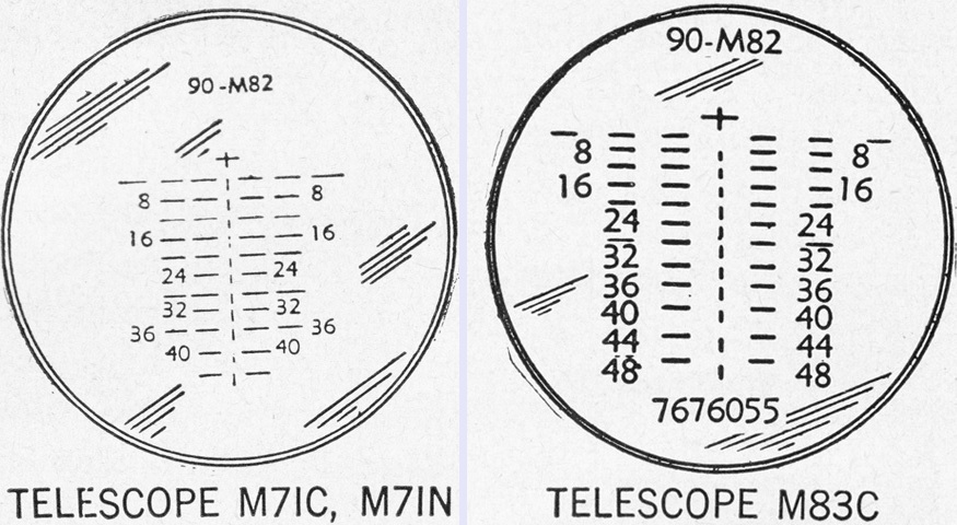
The reticles for the gunner's telescopes are drawn here. The M71C and M71N were 5x instruments with a 13° field of view, while the M83C was a variable 4x to 8x device with a 7°40' field of view at 4x and 4°15' at 8x. The cross represented zero range or deflection and was used for boresighting. Each vertical line and space represented 200 yards (180m), and each horizontal line and space was a deflection of 5 mils. (Picture from TM 9-735 Medium Tanks M26 and M45.)
The periscope M10F is shown from the rear on the left, and its 1x and 6x optical systems are diagrammed on the right. (Picture from TM 9-735 Medium Tanks M26 and M45 and FM 17-12 Tank Gunnery.)
The M10F's reticles are sketched above with the 1x system on the left and the 6x on the right. Each horizontal line and space was a deflection of 5 mils, and the vertical lines were numbered in hundreds of yards. The 1x system had a horizontal field of view of 42°10' and a vertical field of view of 8°10', while the 6x system had an 11°20' field of view. The periscope M4A1 with telescopes M77F or M77H was used as a spare sight. These 1.44x, 9° field of view telescopes used the same reticle as the 6x system of the periscope M10F. (Picture from TM 9-735 Medium Tanks M26 and M45.)
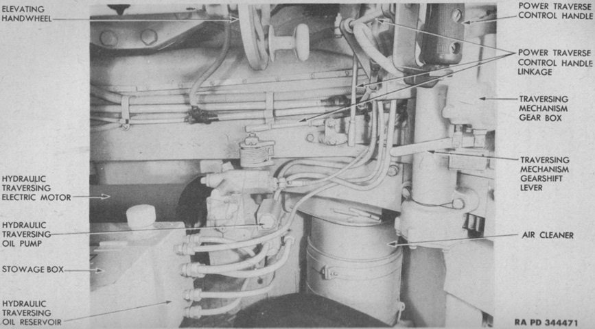
The turret traversing system components are labeled here. (Picture from TM 9-735 Heavy Tank T26E3.)
In addition to the travel lock on the rear of the hull, a gun elevating lock could be actuated inside the turret. It is shown here stowed (left) and in place (right). (Picture from TM 9-1735B Ordnance Maintenance--Medium Tanks M26 and M45 Tracks, Suspension, Hull and Turret.)
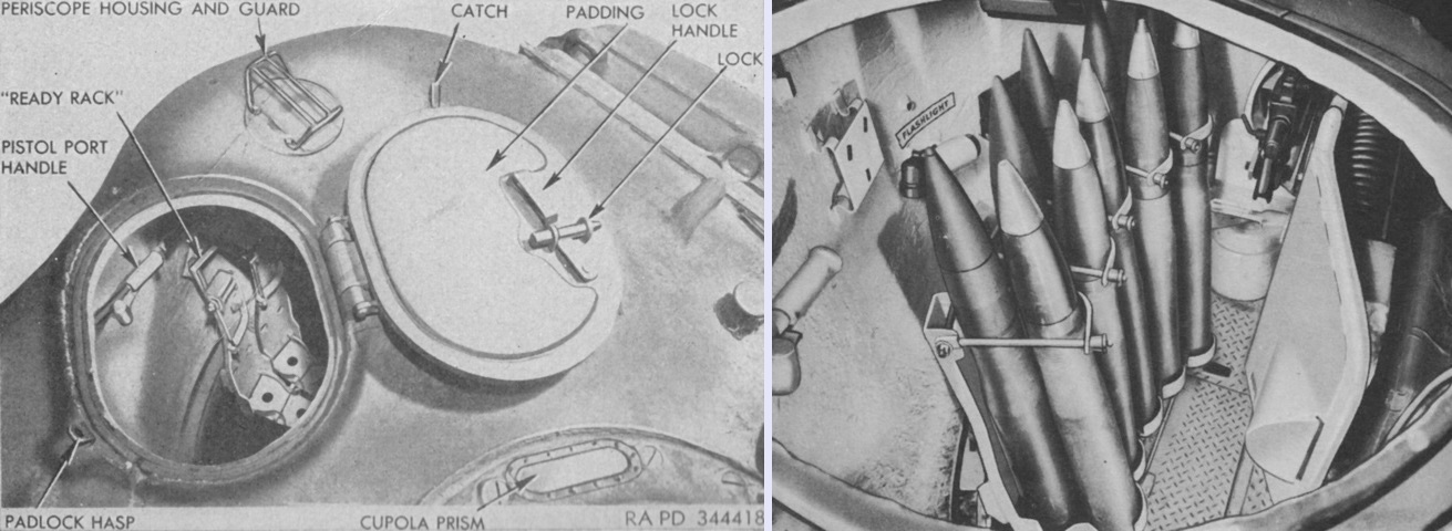
The left image provides a view into the open loader's hatch, and a closer view of the ready rack is on the right. In the right image, the recoil guard for the 90mm gun is to the right, and the .30cal coaxial machine gun can be seen between the ready rack and the recoil guard. (Picture from TM 9-735 Medium Tanks M26 and M45.)
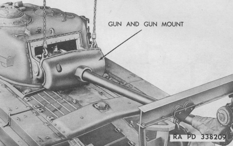
The combination gun mount M67 is being removed. Fifteen slotted screws secured the upper gun shield to the turret, and once this was lifted off, the gun mount could also be removed. The gun mount and weapon weighed 3 tons (2,700kg). (Picture from TM 9-1735B Ordnance Maintenance--Medium Tanks M26 and M45 Tracks, Suspension, Hull and Turret.)
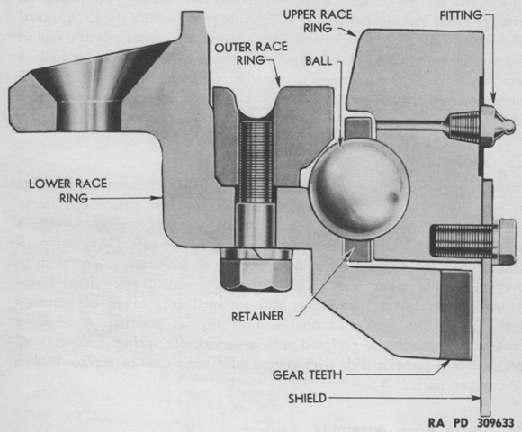
A cross-section of the turret race is drawn here. The upper race was anchored to the turret bottom and rested on 150 hardened steel balls, which were in turn supported by the lower race attached to the top of the hull and held in place by the outer race ring. The balls were each 1.250" (3.175cm) diameter and were kept evenly spaced by 15 retainers. Lubrication fittings were provided as well. (Picture from TM 9-1735B Ordnance Maintenance--Medium Tanks M26 and M45 Tracks, Suspension, Hull and Turret.)
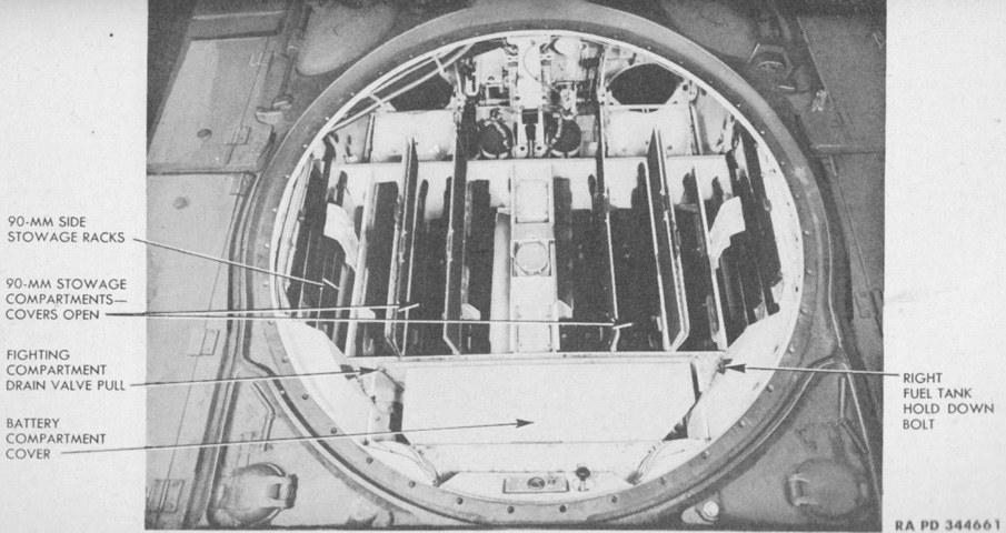
Stowage for the rest of the 90mm rounds was provided in the hull floor. The front of the hull is toward the top of this image, and the drivers' seats can be seen with two fire extinguisher bottles between them. (Picture from TM 9-735 Heavy Tank T26E3.)
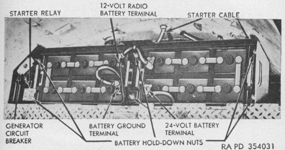
The battery compartment cover seen in the previous image has been removed, showing the installed batteries. (Picture from TM 9-735 Medium Tanks M26 and M45.)
The driver's seat back and fighting compartment floor are shown here. The 90mm ammunition stowage compartment lids create a smooth surface when closed. Hinges and handles for these compartments and the fighting compartment rear floor stowage plates can be seen across the floor. The turret collector (slip) ring box can be seen behind the red fire extinguisher; this provided an electrical connection between the hull and the rotating turret. The upper cable on the side of the collector box provided the 24-volt feed from the vehicle batteries.
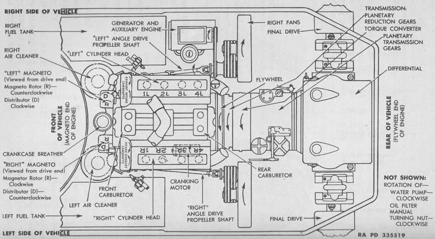
The layout of the engine and powertrain is sketched in this image. The orientation of the engine is opposite that of the vehicle; i.e., the left cylinder bank is on the right side of the tank. (Picture from TM 9-735 Heavy Tank T26E3.)
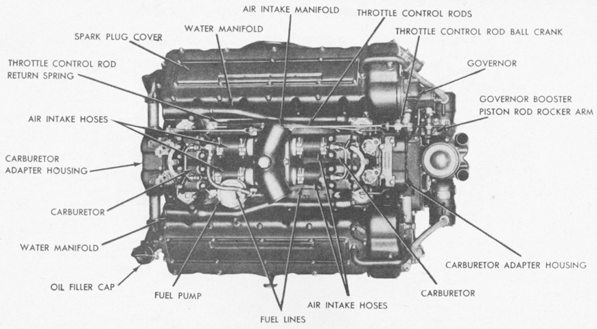
The Ford GAF engine is shown from above. The engine was similar to the GAA of the M4A3 Sherman but lower in height. The carburetors were different between the two designs, with the GAA using two Stromberg NA-Y5G carburetors and the GAF using two Stromberg HD-5 or HH-5 carburetors. The GAF also had a flywheel that was designed to accommodate the tank's torque converter, and the engine's governor was a mechanical flyball type. Displacement was 1,110in³ (18,000cm³) with a 5.4" (14cm) bore and 6" (15cm) stroke, and compression ratio was 7.5:1. (Picture from TM 9-1731B Ordnance Maintenance--Ford Tank Engines (Models GAA, GAF, and GAN).)
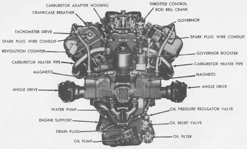
The rear of the engine is labeled here. (Picture from TM 9-1731B Ordnance Maintenance--Ford Tank Engines (Models GAA, GAF, and GAN).)
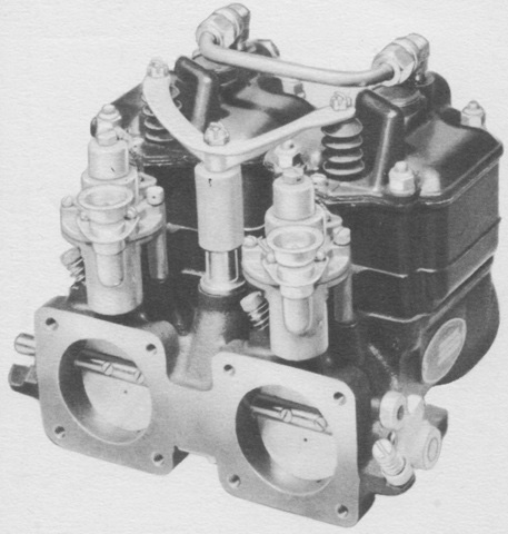
The Stromberg HD-5 carburetor was a double-barrel horizontal type that could be considered as two carburetors built into one unit, as each barrel had a separate fuel system, main metering system, idle system, and accelerating system. One throttle operated both barrels. The idle system of each barrel featured a degasser, which would shut off fuel supply when high manifold pressure was present during deceleration periods. The degasser was controlled by a spring-loaded diaphragm with the engine running, and an electric solenoid would shut off the fuel supply when the ignition was turned off. (Picture from TM 9-1826B Ordnance Maintenance--Carburetors (Stromberg).)
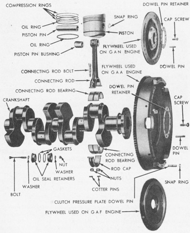
The flywheel of the GAF engine that engaged the transmission's torque converter is visible at the bottom, and can be compared with the conventional flywheel found on the GAA engine in the center. (Picture from TM 9-1731B Ordnance Maintenance--Ford Tank Engines (Models GAA, GAF, and GAN).)
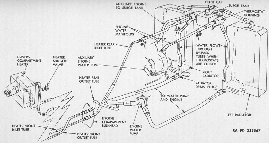
The engine's cooling system is diagrammed in this sketch. Note that the auxiliary generator engine used the main engine cooling system, and also that water from the radiators was routed to the front of the tank in order to supply heat for the crew heater in the driver's compartment. The cooling system had a capacity of 22gal (83L). (Picture from TM 9-735 Heavy Tank T26E3.)
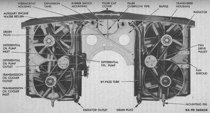
The cooling system was helped by four five-bladed belt-driven fans. The first three American medium tanks that were sent to South Korea after the North invaded were M26s found in the Tokyo Ordnance Depot. These tanks and eight of their crew were lost on 31 July 1950 because the fan belts used when the tanks were rebuilt for action were not the usual type. The replacement fan belts were prone to stretching and caused the engines to overheat once the fans had stopped running. Replacement fan belts had not been received by the time the tanks, which were unable to endure a road march in their condition, were overrun by the enemy. (Picture from TM 9-735 Heavy Tank T26E3.)
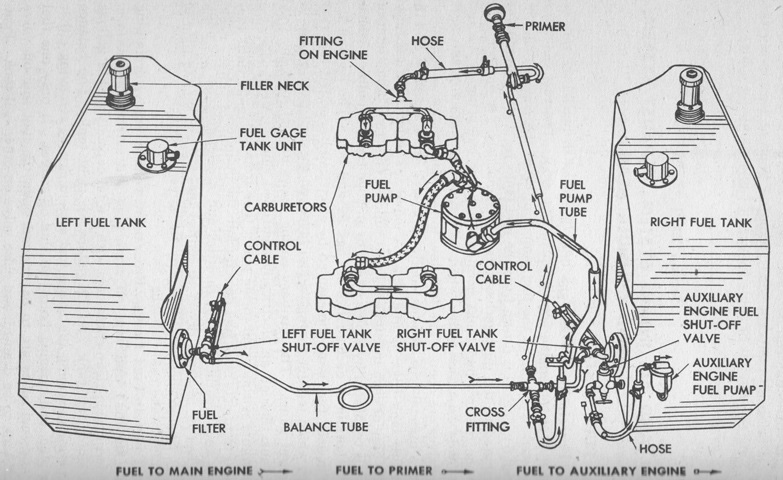
This schematic shows the components of the fuel system. An armor-steel fuel tank was installed on each side of the engine compartment; the left tank had total and usable capacities of 116 and 111½gal (439 and 422.1L), respectively, while the right had total and usable capacities of 75½ and 71½gal (286 and 271L), respectively. A balance tube between the fuel tanks permitted automatic balancing when the both tanks were full and both valves were open. The auxiliary generator engine was tapped into the right fuel tank. (Picture from TM 9-735 Heavy Tank T26E3.)
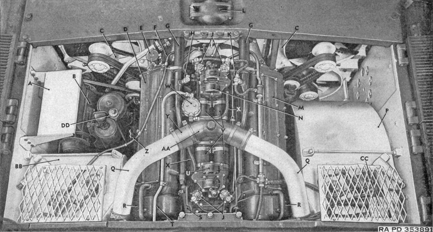
The engine is shown mounted in the tank. A. Generator regulator shield. B. Auxiliary engine and generator. C. Cooling unit. D. "Left" cylinder bank. E. Engine oil filler cap. F. Speedometer shaft. G. Water manifold outlet hose. H. Engine high water temperature warning signal switch. J. Degassers. K. Engine water temperature sending unit. L. Water filler cap cover. M. "Right" cylinder bank. N. "Front" carburetor. P. Left fuel tank. Q. Air intake hoses. R. Spark plug conduit. S. Heater rear inlet tube. T. Fuel tube. U. "Rear" carburetor. V. Air intake tubes. W. Fuel pump. X. Fuel lines. Y. Air inlet hose. Z. Main engine oil level indicator (dip stick). AA. Air intake manifold. BB. Right fuel tank. CC. Engine compartment junction box. DD. Auxiliary engine oil level indicator gage. (Picture from TM 9-735 Medium Tanks M26 and M45.)
This image shows right-hand and front views of the torqmatic transmission. The first speed range was a 1:1 ratio, and moved the tank from 0 to 9mph (0 to 14kph); second range was 1:2.337 and could operate from 6 to 19mph (10 to 31kph); third range was a 1:4.105 ratio and could operate from 12 to 30mph (13 to 48kph). Reverse was 1:1.322 and could operate from 0 to 9mph (0 to 14kph). (Picture from TM 9-1735A Ordnance Maintenance--Medium Tanks M26 and M45, Power Train.)
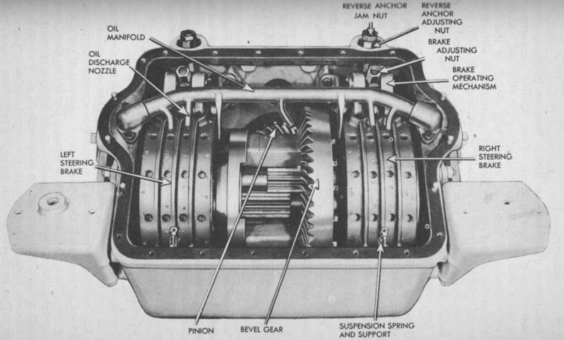
The controlled differential and steering brakes were encased in the same housing carrier. Using one brake to slow its track caused the power to be sent through the differential to the opposite side, increasing the speed of the non-braked track. Applying both brakes would stop the tank. (Picture from TM 9-735 Heavy Tank T26E3.)
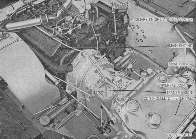
The engine, transmission, and controlled differential are shown mounted in the tank. The power unit, consisting of all three connected assemblies, could be removed from the hull as a single unit. (Picture from TM 9-735 Medium Tanks M26 and M45.)
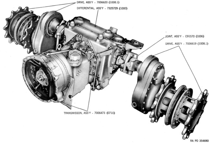
The assembled power train of the M26 is shown here. (Picture from ORD 9 SNL G-226 List of All Service Parts for Tank, Medium M26; Tank, Medium, M45.)
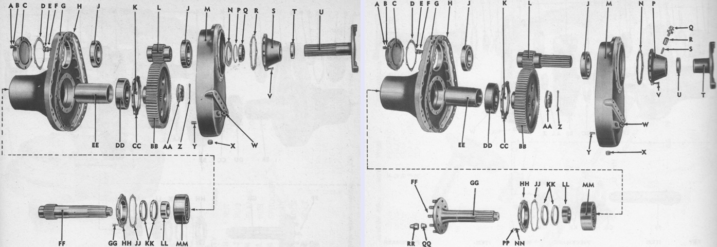
Final drives were available with gear ratios of 19/75, as seen on the left, or 17/76, as seen on the right. The 19-tooth pinion had a 5.381" (13.67cm) outer diameter, 3⅝" (9.208cm) face, and 16 inner splines. The 75-tooth gear was 18.95" (48.13cm) in outer diameter with a 3¼" (8.26cm) face and 16 inner splines. This combination was used with final drive assemblies 7006619, 7006620, 7019216, and 7019217 for steel track and assemblies 7044435 and 7044436 for rubber track. The 17-tooth pinion was 5.04" (12.8cm) in outside diameter, with a 3¾" (9.53cm) face and 16 outer splines. The 76-tooth gear was 19.48" (49.48cm) in outer diameter with a 3¼" (8.26cm) face and 16 inner splines. These were used with final drive assemblies 7020093, 7020094, 7330593, and 7330594, all with rubber track. The legend for the left image is: A. Bolt. B. Washer. C. Retainer. D. Gasket. E. Bolt. F. Washer. G. Cover. H. Gasket. J. Bearing. K. Screw. L. Pinion. M. Carrier. N. Baffle. P. Snap ring. Q. Bearing. R. Gasket. S. Retainer. T. Seal. U. Shaft. V. Screw; washer. W. Plug. X. Plug. Y. Pin. Z. Pin. AA. Nut. BB. Gear. CC. Cap. DD. Bearing. EE. Spacer. FF. Shaft. GG. Bolt; washer. HH. Cap. JJ. Gasket. KK. Seal. LL. Spacer. MM. Bearing.
The legend for the right image is: A. Bolt. B. Washer. C. Retainer. D. Gasket. E. Bolt. F. Washer. G. Cover. H. Gasket. J. Bearing. K. Screw. L. Pinion. M. Carrier. N. Gasket. P. Retainer. Q. Vent, ass'y. R. Coupling. S. Nipple. T. Yoke, ass'y. U. Seal. V. Screw. W. Plug. X. Plug. Y. Pin. Z. Pin. AA. Nut. BB. Gear. CC. Cap. DD. Bearing. EE. Spacer. FF. Stud. GG. Shaft. HH. Cap. JJ. Gasket. KK. Seal. LL. Spacer. MM. Bearing. NN. Washer. PP. Bolt. QQ. Dowel. RR. Nut. (Picture from ORD 9 SNL G-226 List of All Service Parts for Tank, Medium M26; Tank, Medium, M45.)
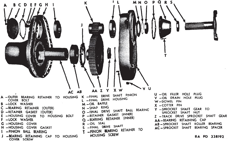
The downward direction of the final drive gearing is visible in the pictures above, and its effect on the drive sprocket position can easily be seen on this tank with its lack of rear fenders. The final drive housings were made of cast iron.
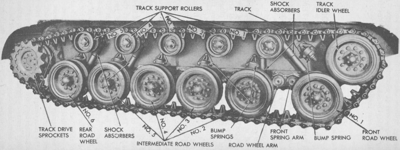
The nomenclature of the suspension components is given here. The vehicle used for this picture was the medium tank T25E1, which can be thought of as an M26 with lighter armor. Note the narrower tracks and different drive sprocket. The T25E1 was not selected for production. (Picture from TM 9-735 Heavy Tank T26E3.)
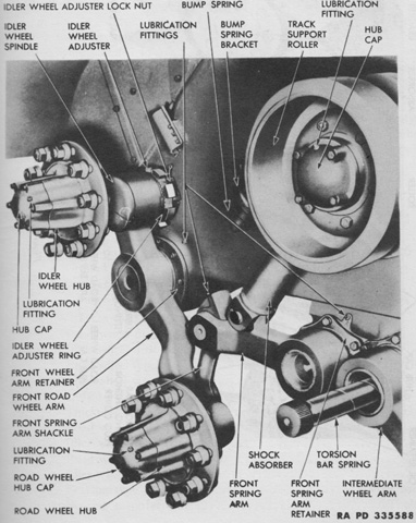
The idler wheel was mounted on an eccentric spindle on the upper end of the first road wheel arm. When the first road wheel encountered an obstacle and moved upward, the idler wheel consequently moved forward and downward and thereby reduced the slack caused in the track by the first road wheel's movement. The front spring arm shackle transmitted the movement of the first road wheel to the front spring arm, which was attached to the torsion bar. (Picture from TM 9-1735B Ordnance Maintenance--Medium Tanks M26 and M45 Tracks, Suspension, Hull and Turret.)
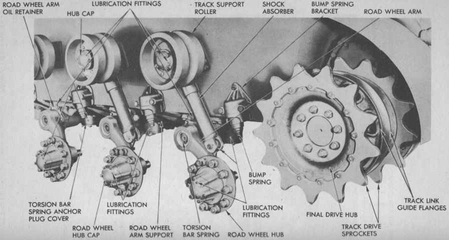
The rear suspension and drive sprocket of the T25E1 are shown without the road wheels or tracks mounted. When new, the return roller tires were 14" (36cm) in diameter. (Picture from TM 9-735 Heavy Tank T26E3.)
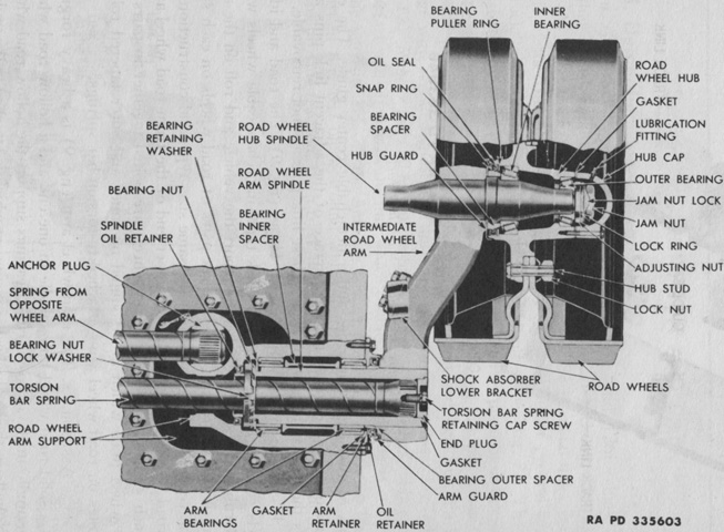
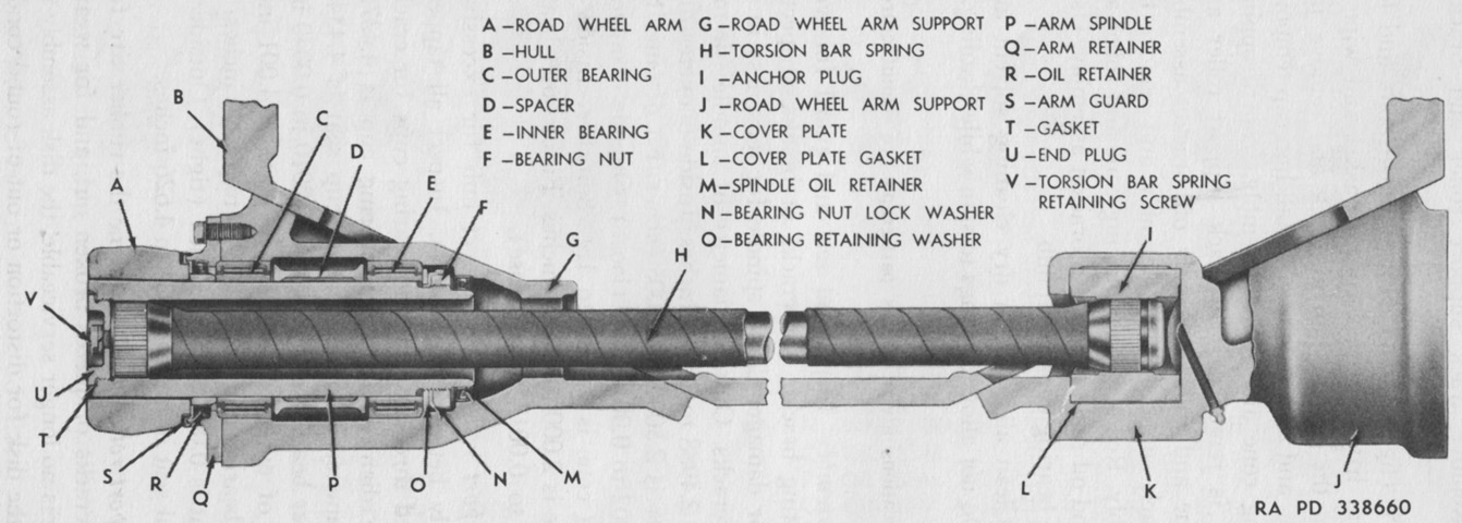
A cross-section of a road wheel station is shown here. Note the anchored end of the torsion bar from the opposite side of the tank; due to their length, the torsion bars of the opposite sides overlapped each other. Consequently, the wheels on either side of the tank were slightly offset from each other. When new, the road wheel tires had an outside diameter of 26" (66cm), and were 1½" (1.3cm) thick. (Picture from TM 9-1735B Ordnance Maintenance--Medium Tanks M26 and M45 Tracks, Suspension, Hull and Turret.)
The torsion bars were made from high carbon steel, and serrations at the ends of the bars matched serrations in either the road wheel arm spindles or the anchor plugs. They were intended to provide cushioning in one direction, and were marked with an arrow showing direction of rotation and either an "L" or "R" to denote on which side of the hull they should be installed. They were 77⅛" (195.90cm) long and had a maximum diameter of 2½" (6.4cm) over the wrapping. (Picture from TM 9-1735B Ordnance Maintenance--Medium Tanks M26 and M45 Tracks, Suspension, Hull and Turret.)
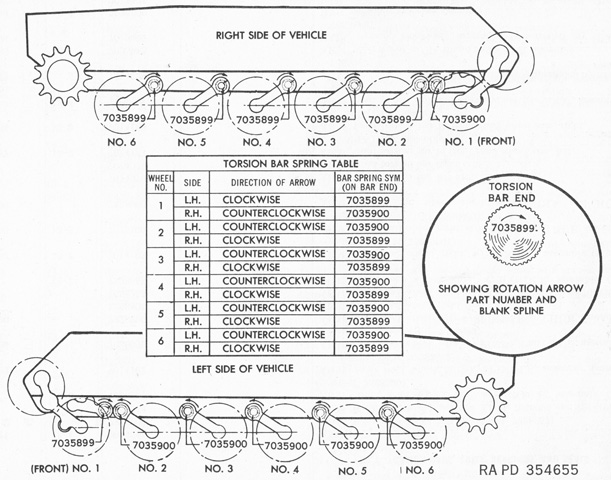
The prescribed orientation for the torsion bars is diagrammed. Since the front road wheels used leading arms instead of trailing arms, these used the torsion bars found on the rest of wheels on the opposite side of the hull. (Picture from ORD 9 SNL G-226 List of All Service Parts for Tank, Medium M26; Tank, Medium, M45.)
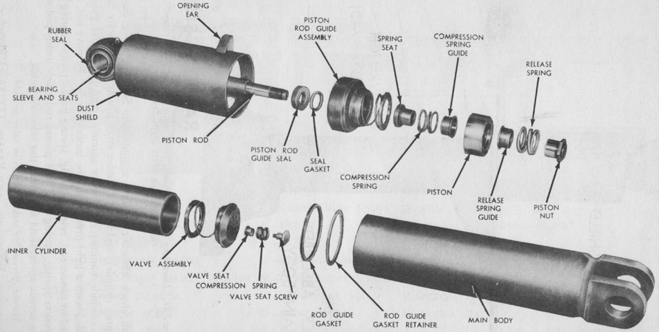
An exploded view of one of the model 990-A2 double-acting, telescopic hydraulic shock absorbers is provided in this image. They held 35.1oz (1,040mL) of fluid, and had a 7⅝" (19.37cm) length of travel. (Picture from TM 9-1735B Ordnance Maintenance--Medium Tanks M26 and M45 Tracks, Suspension, Hull and Turret.)
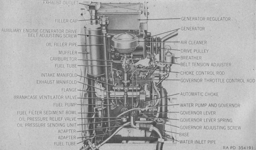
The mounted auxiliary generator and engine are seen here from the side. The engine was a Waukesha G-TGU constant-speed (1,800rpm), 4-cylinder, liquid-cooled, 4 cycle gasoline engine that produced 13.6 horsepower. It could be manually started via a rope starter if there was not enough current in the batteries for electrical starting. (Picture from TM 9-735 Medium Tanks M26 and M45.)
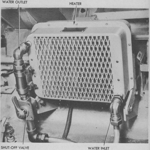
The heater mounted in the drivers' compartment is shown here. A fan in the heater spread hot air when activated. (Picture from TM 9-735 Heavy Tank T26E3.)
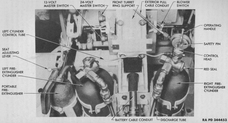
The fixed fire extinguisher system consisted of a 10lb (4.5kg) CO2 cylinder mounted on each side of the turret ring support in the driver's compartment, and was routed to discharge into the engine compartment. They were activated simultaneously by using the lever on the right cylinder's control head or by pulling the handle on the hull exterior behind the assistant driver's door. In addition, two portable 4lb (2kg) fire extinguishers were carried, one stowed in the driver's compartment as shown here and one behind the commander's station. (Picture from TM 9-735 Heavy Tank T26E3.)
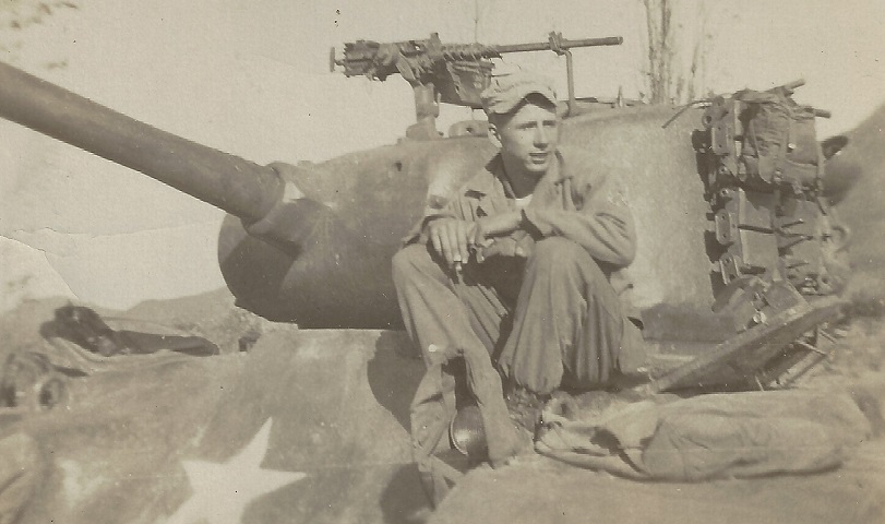
Positioned between and behind the two turret hatches, the mount for the rooftop .50cal machine gun was found to be difficult to use in action. During the Korean War, both Army and Marine crews improvised mounts placed in front of the commander. This tank belonged to the Army's 73d Tank Battalion and was photographed in late 1950. (Picture courtesy Lou Manz.)
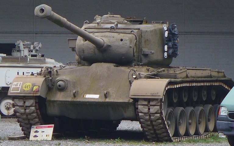
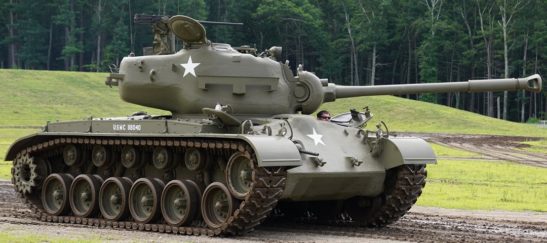
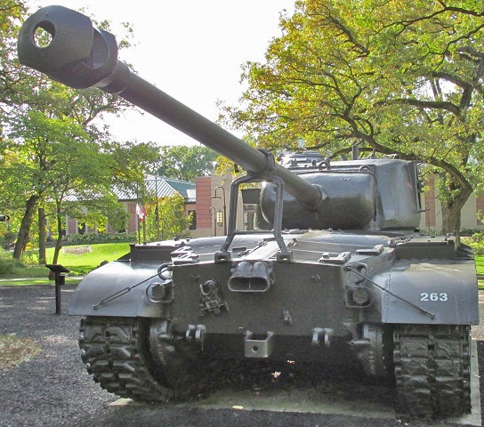
The single-baffle muzzle brake and bore evacuator on the 90mm gun M3A1 could lead to this vehicle being mistaken as an M46 Patton, but the stowage boxes instead of engine mufflers on the rear fenders and relatively low drive sprocket mark it as an M26A1 Pershing. (Picture courtesy Dackelone.)
Identification is made easier from this side view. All hatches are open, and the .50cal machine gun and spotlight are mounted atop the turret roof. (Picture courtesy Rob Nelson.)
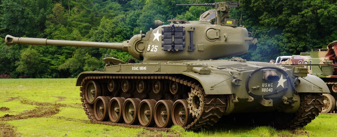
Note the relocated gun travel lock, which is on the engine deck rather than athwart the engine exhaust port. An infantry phone box has been mounted to the upper rear hull plate, and a track connecting fixture is stowed on the turret side beside the section of spare track. The machine in the background is a British FV432 armored personnel carrier modified to resemble a German Sturmgeschütz from World War II. (Picture courtesy Rob Nelson.)
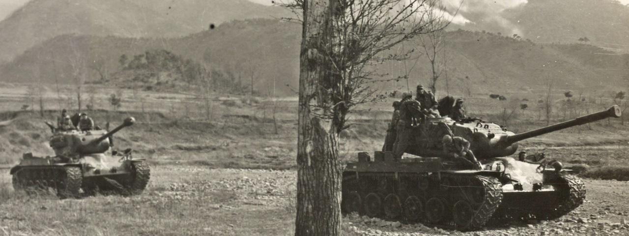
A Marine Corps M26A1 leads an M26 out of a river bed in the central front of the Korean theater. The bore evacuator and lighter muzzle brake of the M26A1 are easily contrasted with both tank types in the frame. (Picture by Sgt D.R. Thompson; available from the National Archives.)
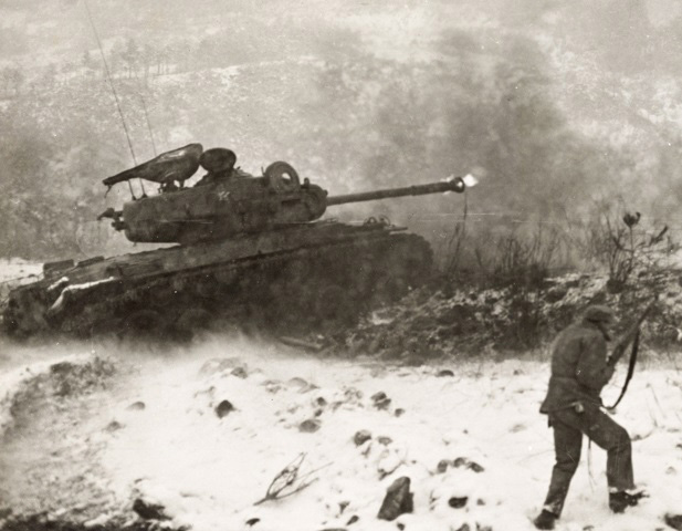
The action of the muzzle brake is illustrated by this Marine Corps tank firing on an enemy emplacement. Unfortunately for PFC R.A. South in the foreground, the brake directs the blast to the sides and rear of the tank. The .50cal machine gun is covered, and there is a spare road wheel stowed on the turret rack normally used for the drivers' foul weather hoods. (Picture taken 27 November 1951 by TSgt R.E. Olund; available from the National Archives.)
Compared to tanks armed with the 90mm gun M3, the T15E2 gun was certainly more imposing and unwieldy. Nonetheless, its chamber capacity was 488in³ (8,000cm³) versus the M3's 300in³ (4,920cm³) and maximum powder pressure was 41,500psi (2,920kg/cm²) versus the M3's 38,000psi (2,670kg/cm²). These increases, along with the 70- versus 50-caliber barrel enabled the T15E2 to fire the T43 APBC shot at 3,200ft/sec (980m/s), compared to the M3 firing the T33 APBC at 2,800ft/sec (850m/s). While the T33 could pierce the Pz.Kpfw.Panther frontally from 1,100 yards (1,000m), the T43 fired from the T15E2 was thought to be able to perform the same feat from 2,600 yards (2,400m). (Picture from Tank Data, volume 2.)
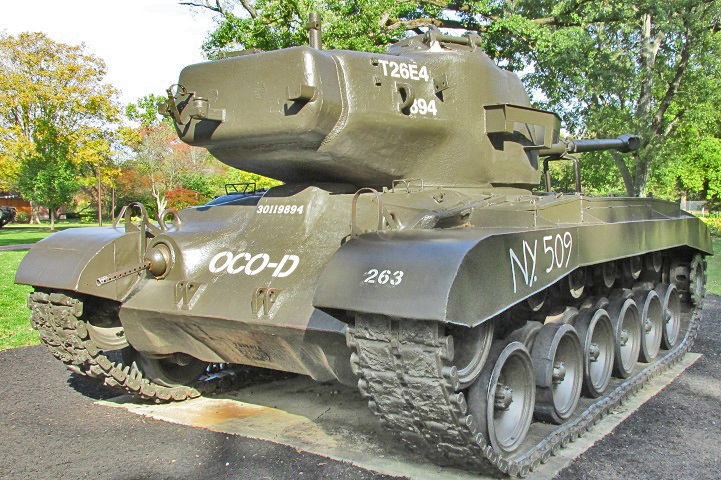
With the turret reversed, there is not much to differentiate a T26E4 from an M26. The large counterweight added to the turret bustle is one visual clue. The .50cal machine gun stowage mounts were necessarily relocated to the end of the counterweight.
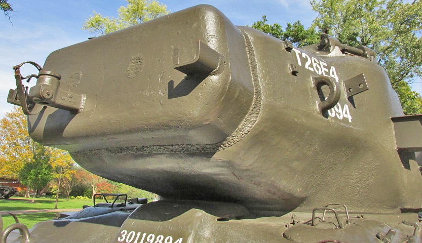
Further details of the counterweight and the machine gun mounting can be seen here.
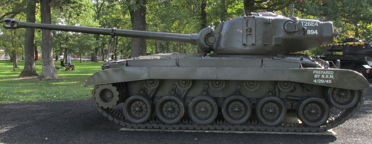
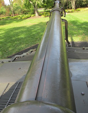
From the side, however, the very long gun tube is apparent even with the turret traversed over the rear hull. The travel lock was heightened to decrease the chance of ground strikes if the vehicle encountered an obstacle. Note that on this vehicle, the drive sprocket lacks the teeth to engage the track end connectors; the forward shock absorber is also lying across the two forward road wheel arms.
Unlike on the M26, which attached the travel lock to the engine exhaust port, the new travel lock was mounted on the rear hull.
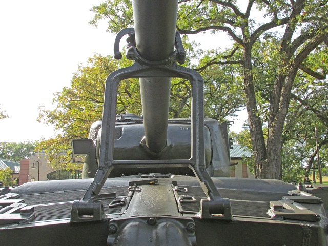
Further details of the construction and mounting of the travel lock can be seen here.
This tank features the later hull ventilator and lacks the second set of driver's periscopes.
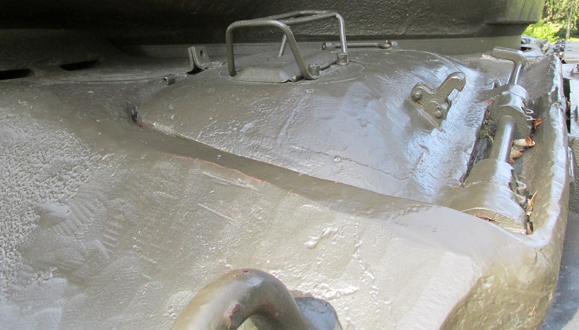
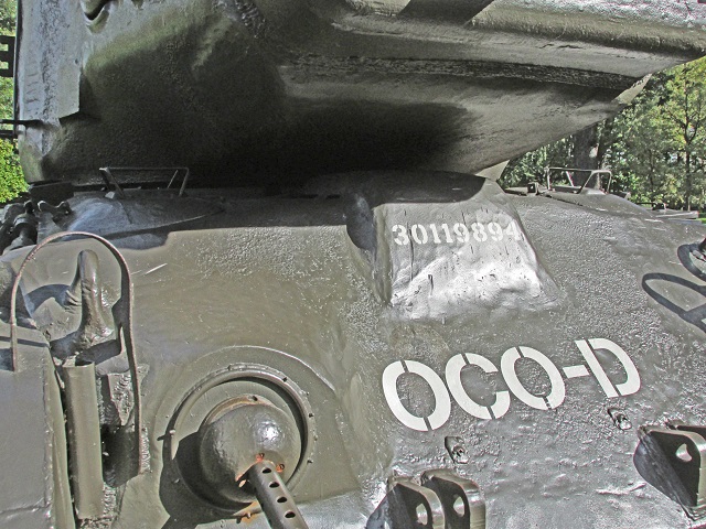
Details of the driver's door can be seen on a hull without the second set of periscopes.
The location where the periscopes would have been mounted can still be seen.
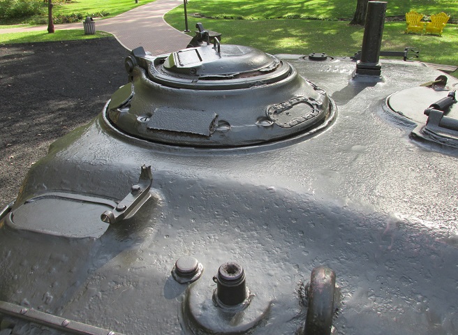
The commander's cupola and vane sight can be seen on the right side of the turret. Behind this is the mount for the .50cal machine gun and beyond that is an antenna mount. In front of the commander's cupola is the aperture for the gunner's periscope M10E4. A spotlight mount is in the foreground next to the lifting eye.
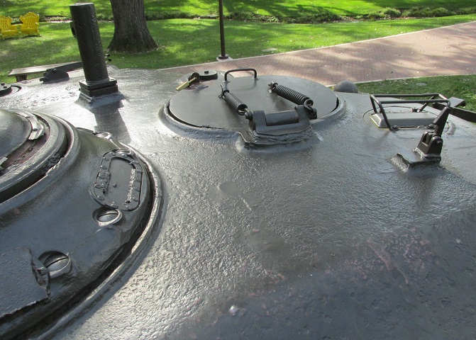
The loader's hatch opens to the front, and his rotating periscope can be seen to his front left.
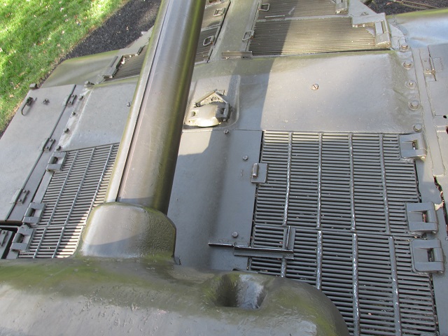
The air intake and exhaust grilles can be seen on the deck, and the engine coolant filler cap can better be seen from this angle.
A keyway is found in the gun tube of the T15E2.
