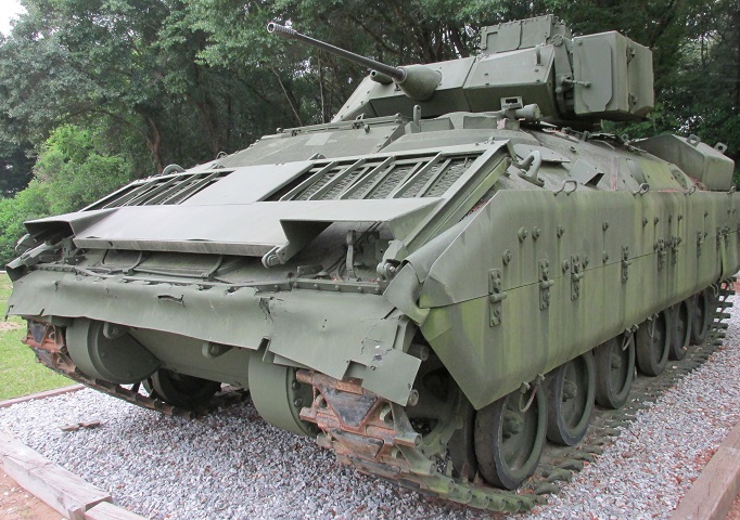
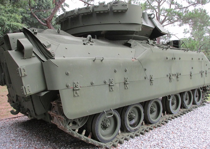
Cavalry Fighting Vehicle M3 Bradley in Fort Benning, Georgia.
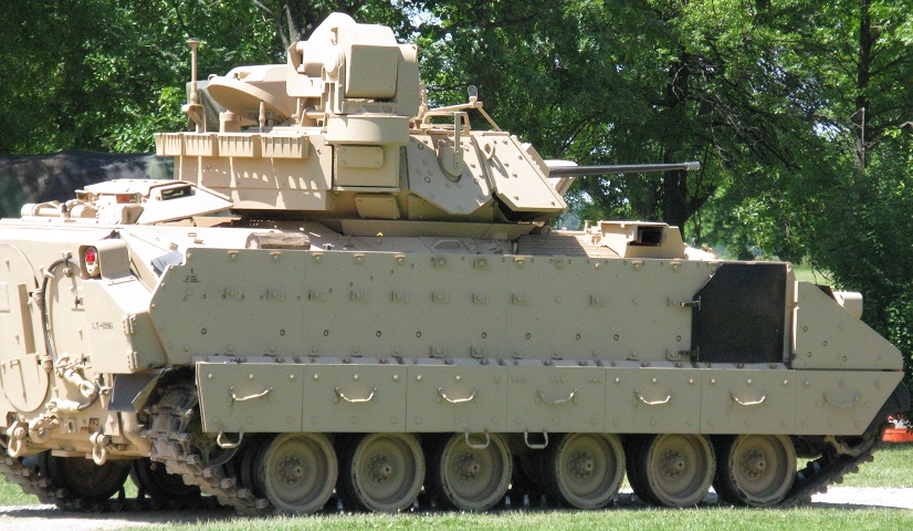
Externally, the M3 and M2 Bradleys are almost identical; both even featured three periscopes in the rear roof between the ramp and the deck hatch. The side firing ports and their associated periscopes are blanked off on this vehicle, however, revealing it to be the former. This vehicle presents an interesting mix of features found on both early and later machines. The headlights and indicators have been dismounted, and the tie-downs for the swim barrier are loose, allowing the cover to come untucked.
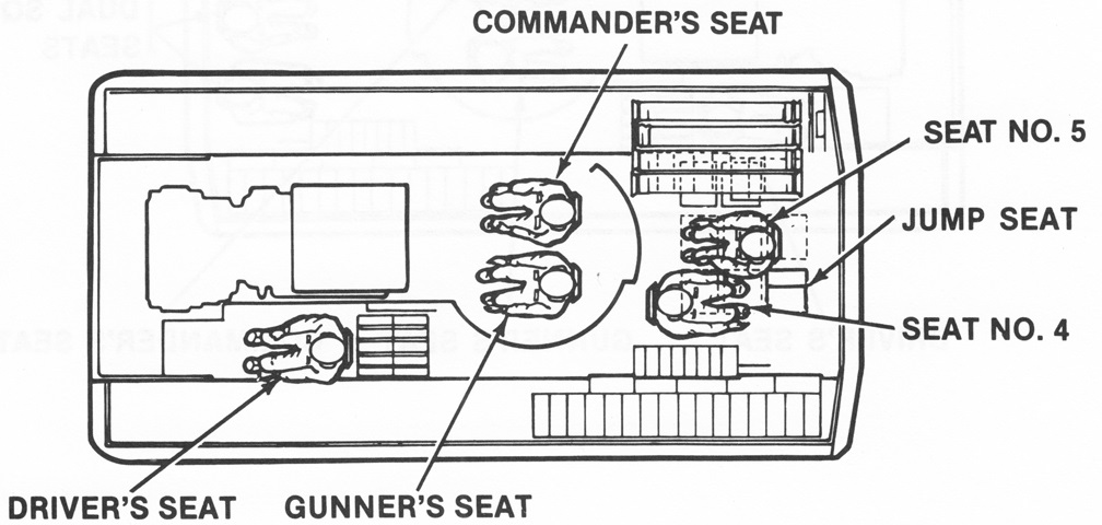
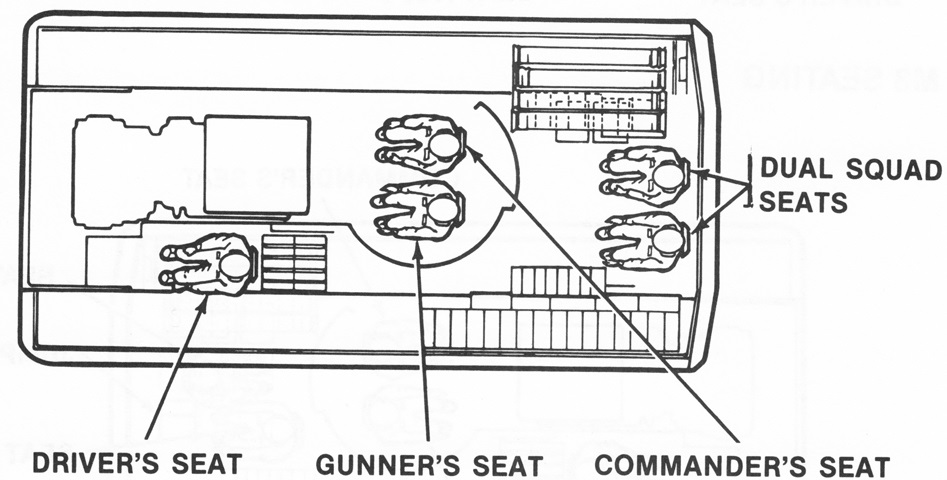
The positions of the crew are detailed in this drawing. Spare missile stowage occupies the right rear corner of the hull. (Picture from TM 9-2350-252-10-1 C1.)
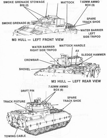
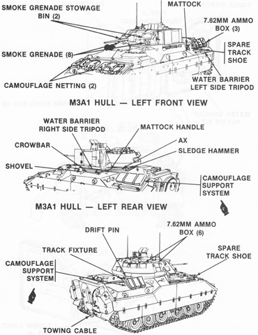
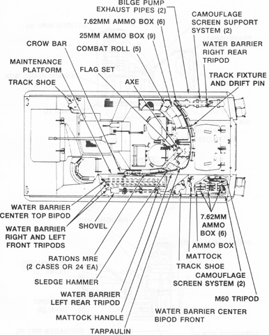
External stowage is listed in this diagram. (Picture from TM 9-2350-252-10-1 C1.)
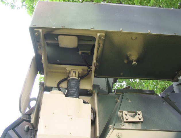
The smoke grenade launchers are not mounted, and the wiring for their operation has been taped off. The four lugs on the turret front show where the stowage box for extra smoke grenades would be placed. The pull knob on the TOW launcher frame was part of the system to manually elevate the launcher to firing position. A 14mm ratchet wrench could be placed onto a drive shaft behind the knob to raise the launcher, then when finished the knob could be pulled and the launcher would lower back to its stowed position. The blanking plate with two bolts on the hull shows where a periscope would have been mounted.
The smoke grenade stowage box is in position on this vehicle, but the barrel for the 25mm chain gun is not installed. Two of the driver's periscopes can be seen in the foreground, and two periscopes are in place in the hull side, including behind the driver where the vehicle in the previous picture had a blanking plate attached.
Since the cavalry scouts were not provided with firing port weapons, the firing ports themselves were blanked off and eventually omitted altogether. The blanking plates for the hull periscopes can be seen on the upper hull.
In contrast, both side hull periscopes are mounted on this machine, as noted above.
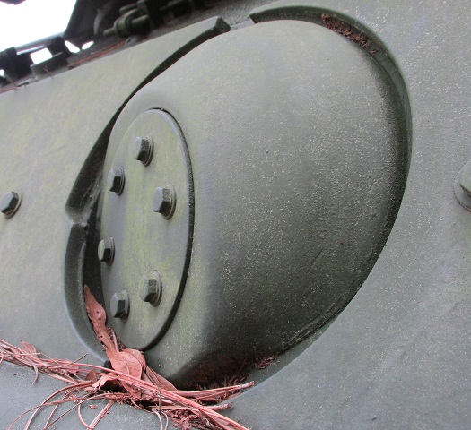
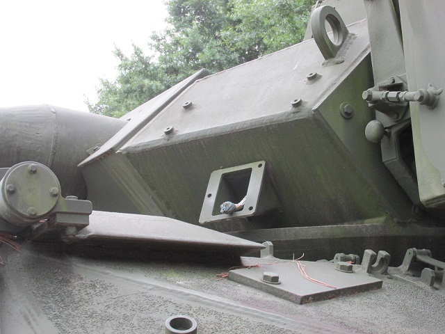
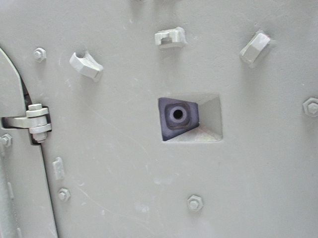
A closer view of one of the blanked-off firing ports and its surrounding armor is provided here.
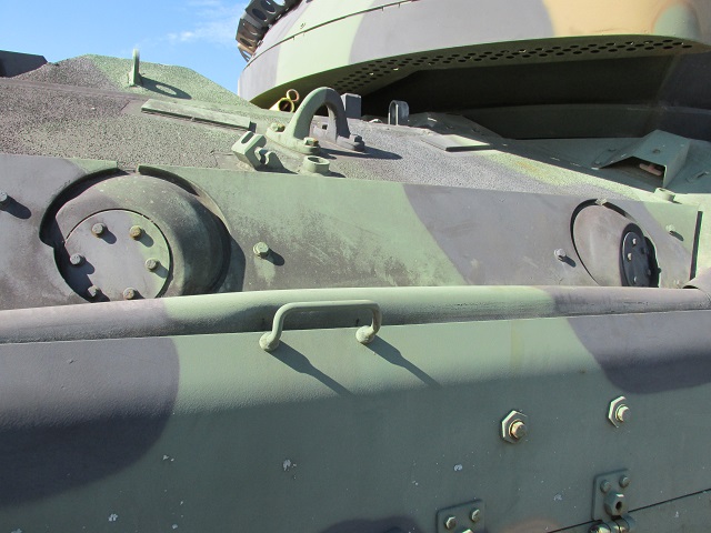
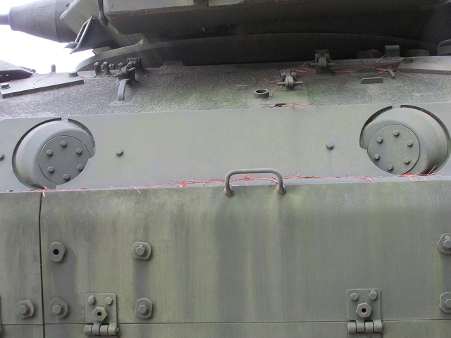
This vehicle retains blanked-off firing ports on the right side, and the periscopes above them have been eliminated. A handle for activating the fire extinguishers is visible under a guard on the hull to the right.
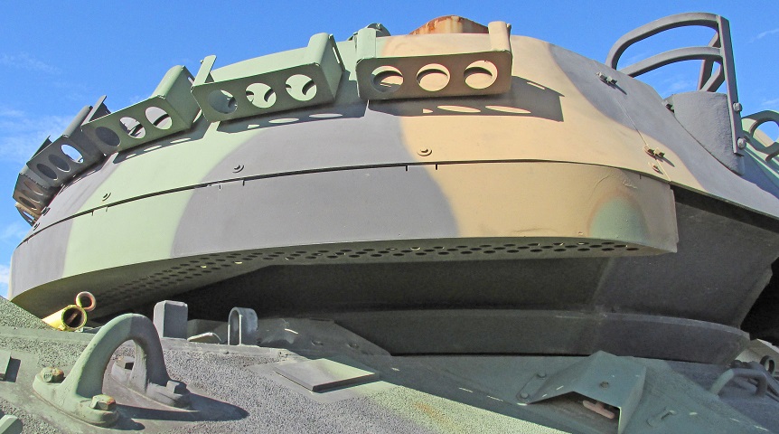
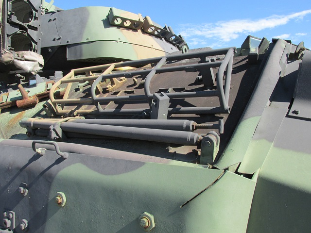
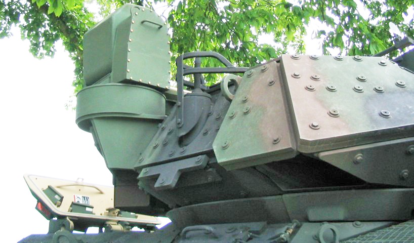
The early stowage rack can be seen here, which slants inward toward the turret roof. Machine gun ammunition could be stowed in the brackets ringing the stowage rack, and drainage holes were present in the bottom of the stowage rack.
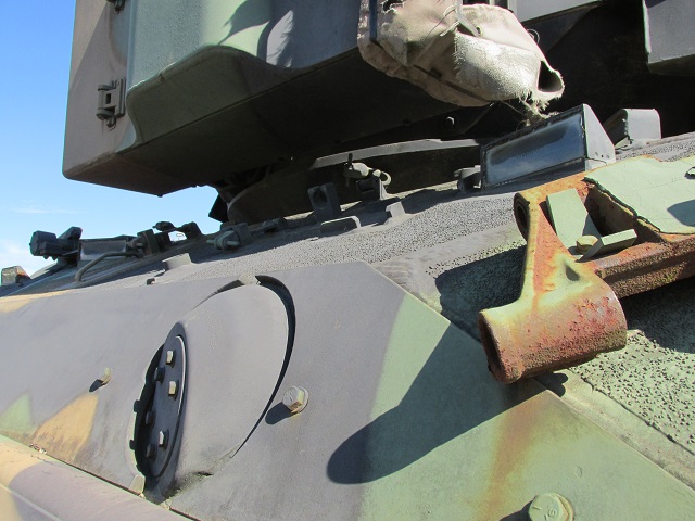
Spaced armor along the turret side and antenna guard is highlighted here. Expended machine gun ammunition cases were ejected through the aperture in the turret's front right corner.
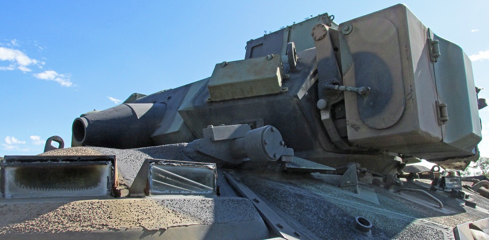
The firing ports and periscopes have been completely eliminated from the right side of the vehicle, and it has been fitted with the later-design turret bustle stowage rack with more vertical sides and better-defined corners. The engine exhaust deflector can be seen on the top of the front hull, and the spaced armor around the turret antenna is missing.
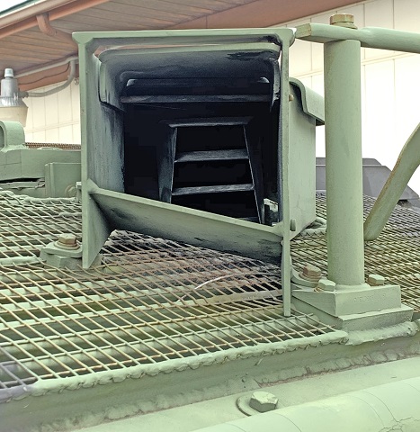
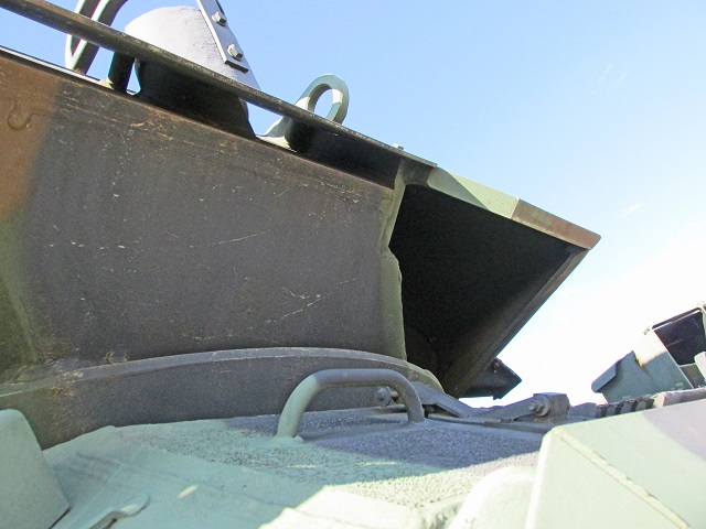
The exhaust deflector and guard are detailed in this image.
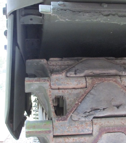
The spaced armor plates of the skirt can be seen from this angle. Details of the single-pin track can be gleaned, and the rear mud flap has been torn away.
Pioneer tools were stowed at the left rear of the hull.
The swim barrier can be seen here under its protective cover.
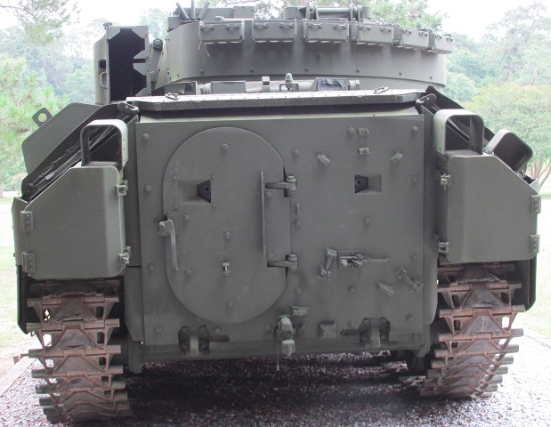
The firing ports in the rear ramp on this vehicle have not been plated over, and the tool stowage on the hull's left rear is covered.
The three periscopes in the rear hull roof are shown here, as well as the stop for the rearward-opening roof hatch.
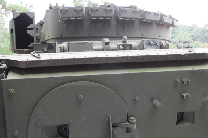
The hatch with its non-slip surface and the periscopes can be better seen from above.
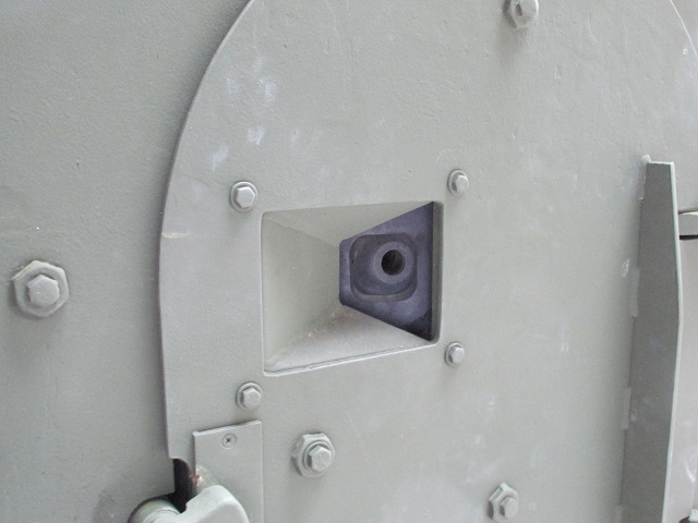
A close-up of the firing port in the ramp door is provided here.
This picture provides a similar view of the firing port in the ramp itself. Hooks to stow a towing cable can also be seen.
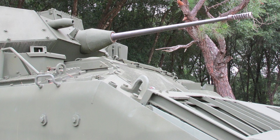
The multi-baffle muzzle brake of the M242 25mm gun can be seen here along with the shroud for the coaxial machine gun. Eight hundred 7.62mm rounds were carried in the machine gun's ready box. On the turret between the coaxial machine gun and chain gun is the attachment for the commander's ring sight, which is missing from this vehicle.
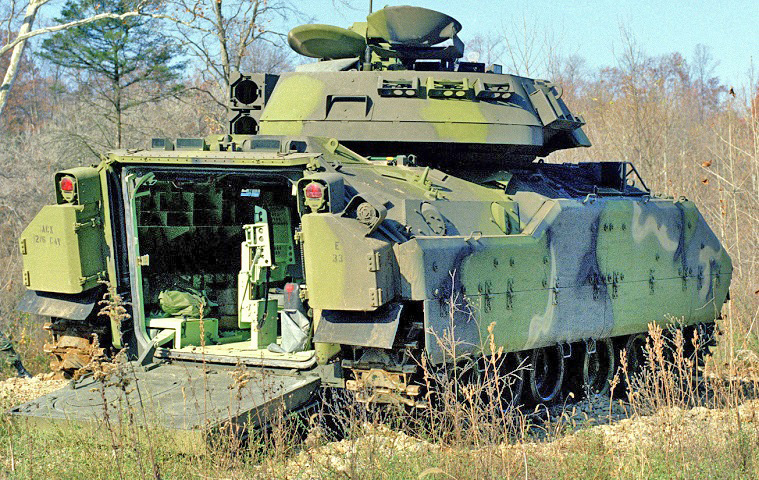
With the ramp lowered, the seats for the scouts can be seen in the center of the entryway. (Picture taken 1 Jan 1983 by Steve Catlin; available from the National Archives.)
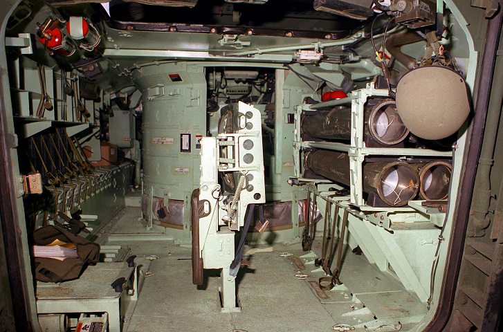
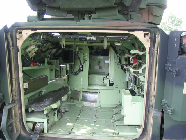
The interior of the passenger compartment is shown here. TOW missiles are stowed along the right wall, and the reason behind the elimination of the right-side periscopes can therefore be seen. Seats for the two scouts are mounted in the center. The seats fold down so that the man on the vehicle's right sits facing forward, and the man on the left faces to the rear. The cargo hatch is open, and the three periscopes in the rear roof can just be seen at the top of the image. There is a tunnel to the left of the turret that connects the driver's position with the rear compartment. (Picture taken 20 Apr 1990 by SPC Diana Lindsey; available from the National Archives.)
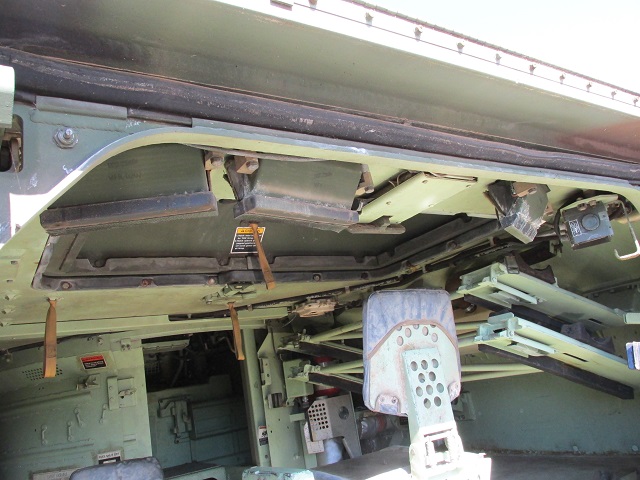
A closer view of the cargo hatch is presented in this image. The three periscopes are visible, and the right-hand seat is unfolded. The empty stowage racks for the TOW missiles on the right of the compartment are folded up.
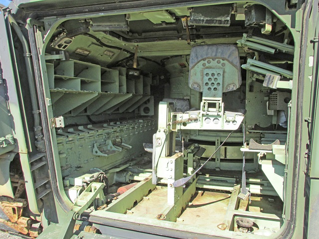
A general view of the passenger compartment reveals that much of the floor is missing. The seatbelt for the deployed seat hangs down from the base, and copious space is available for ammunition stowage on the left wall.
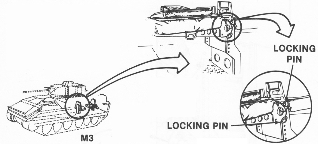
The squad seats of the M3 were equipped with locking pins like those found in the M2 Bradley. (Picture from TM 9-2350-252-10-1 C1.)
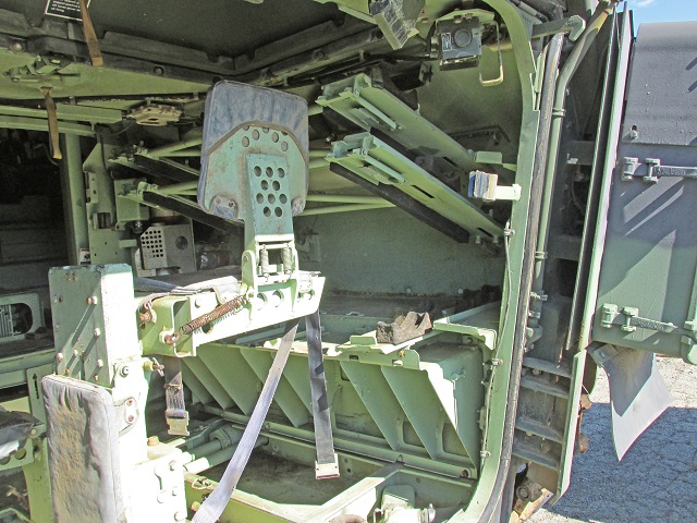
The right side of the passenger compartment is highlighted here, with the folded TOW stowage racks and spaced armor on the rear hull visible.
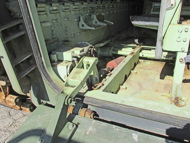
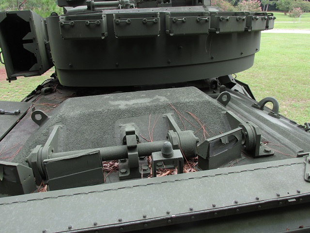
The missing floor plates allow us to view the hydraulic cylinder that raised and lowered the rear ramp. Further forward are the torsion bars for the rear road wheels. The road wheels on each side are slightly offset from one another, and the reason behind this is obvious once the torsion bar setup can be seen.
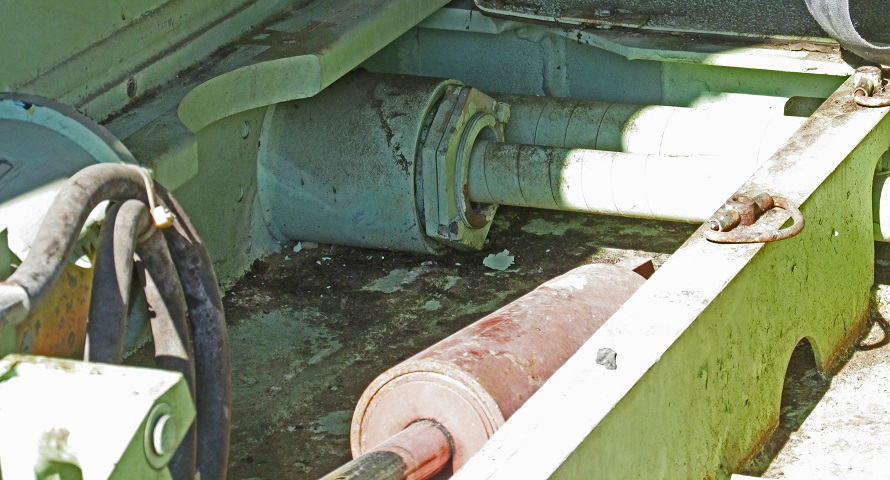
A closer view of the torsion bars and the hydraulic cylinder is provided here.
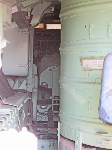
The turret is offset to the right, providing a passage between the driver's position and the passenger compartment. Daylight is visible coming through the driver's periscopes, and one of the hull roof periscopes can be seen to the left of the turret.
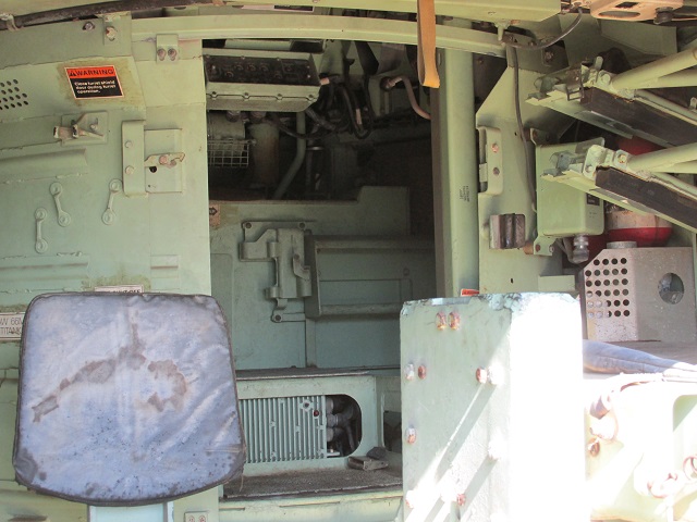
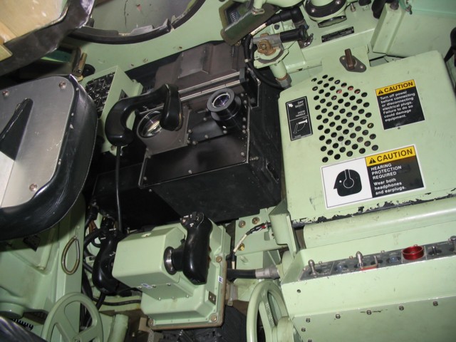
The turret shield had a sliding door that provided access. The corrugated box on the turret floor housed the relay box circuit breaker; a warning light and reset switch can be seen just to the left of the opening through which cables are visible. The weapon control box can be seen near the top of the opening in the turret shield.
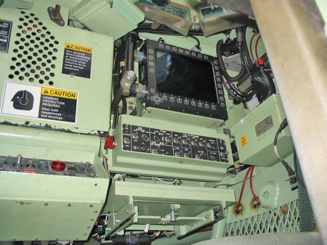
A zoomed view of the turret interior is provided in this image. The gunner's seat is on the left, and his control handles are directly to his front. On the front side of the vertical black control handles could be found palm switches at the bottom that released the turret brakes and activated the turret drive, and trigger switches at the top for firing the turret weapons. The button visible at the top of the rear of the handle was the fast turret switch, which increased the turret rotation and gun elevation rates. The black button in the circular recess at the bottom of the control handle box was the drift button to reduce the amount of drift in the turret stabilization system. The large handwheel to the gunner's right was for manual weapon elevation; a similar traverse handwheel was to his left.
The weapon control box is above and to the right of the elevation handwheel. On the left are the arm-safe-reset switch and indicator light, with the sear indicator light (which indicates that the 25mm gun bolt is in the sear position and blinks when the gun bolt is in the misfire position) directly above. The misfire button that brings the 25mm gun bolt back to the sear position after a misfire is to the right of the arm-safe-reset switch. The three buttons and upper indicator lights are, left to right, the armor-piercing single shot mode button, armor-piercing low rate of fire button, and armor-piercing high rate of fire button. Below these buttons and hidden by the rim of the control box are similar buttons for high-explosive ammunition. To the right of the high rate of fire buttons is the coaxial machine gun selector button. To the right of the coax machine gun button is an indicator light that flashes when the end of a 7.62mm or 25mm ammunition belt passes sensors in the ammunition cans. The affected weapon will then stop firing. Below this indicator light, and again hidden by the rim of the control box, is the low ammunition override button, which when pressed will allow the affected weapon to resume firing. The low ammunition light will then remain lit. Separated by the white line on the right side of the panel are the controls for the smoke grenades. The grenade launcher switch and indicator light are on the extreme right, and above and to the left is the trigger button and indicator light, which fires all eight smoke grenades.
Visible just to the right of the black gunner's control handle is the annunciator box, with lights alerting the gunner to different conditions. The top row of warnings, left to right, warn of a malfunction in the TOW electrical system; an open driver's or cargo hatch; a malfunction in the 25mm gun feeder; and that turret manual drive has been selected. The lights on the bottom row, left to right, indicate that the armor-piercing and high explosive ammunition switches have been reversed; the triggers have been disabled due to the weapons being aimed in a no-fire zone on the vehicle; the 25mm gun misfire protection system is malfunctioning; and that the turret drive system is malfunctioning.
Above the annunciator box is the TOW control box. Just visible across the top of the image are the launcher up-down switch and indicator light; the TOW firing mode button and indicator light; and the missile tube 1 or 2 buttons and indicator lights. To the bottom left is the TOW test button and indicator light. To the right of this button are three annunciator lights: the top left is for a malfunction in the TOW tracking system; beside this is for a malfunction in the command and guidance electronics system; and hidden from our view below the tracking system error light is a light to indicate a malfunction in the TOW power supply system.
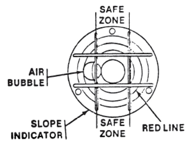
The gunner was provided with a bubble level to ensure that he would not attempt to fire the TOW missile while the vehicle was too canted. If the bubble was out of the safe zone, the gunner was to instruct the driver to find flatter ground. (Picture from TM 9-2350-252-10-2.)
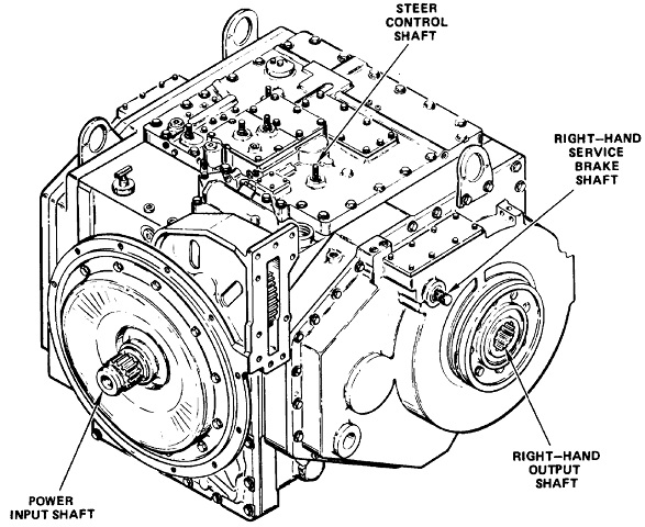
The right rear of the HMPT-500 transmission is sketched here. Its maximum input torque, speed, and horsepower were 1020 ft-lb, 2600rpm, and 500, respectively. The nominal output torque was 9200 ft-lb, nominal forward speed was 3100rpm, nominal reverse speed was 600rpm, and nominal steering torque per side was 5500 ft-lb. (Picture from TM 9-2520-270-34.)
The jump seat found in the M3 has been omitted. (Picture from TM 9-2350-252-10-1 C1.)
Revised external stowage is seen here. (Picture from TM 9-2350-252-10-1 C1.)
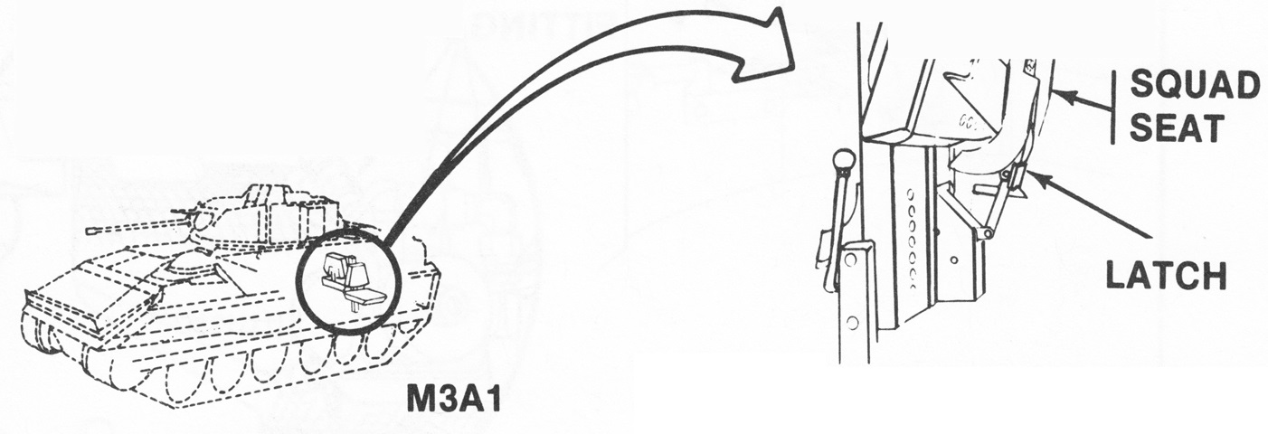
The squad seats in the M3A1 were changed so that locking latches replaced the earlier locking pins. (Picture from TM 9-2350-252-10-1 C1.)
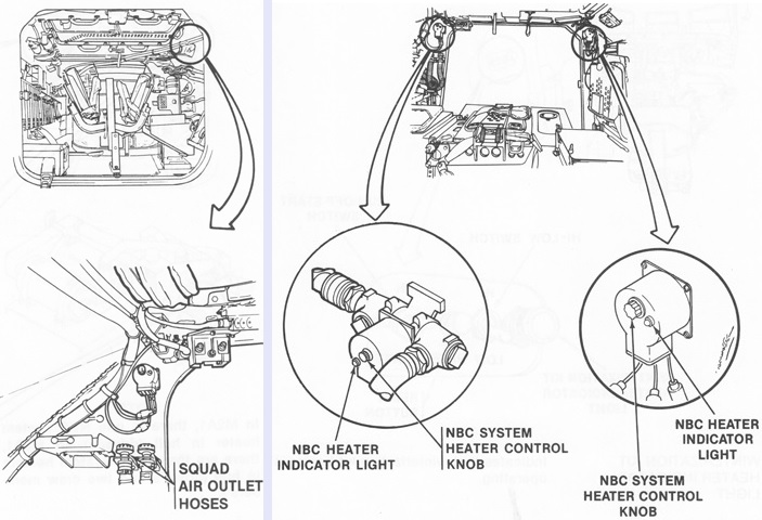
In contrast to the infantry fighting vehicle, the cavalry fighting vehicle enabled all five crew to connect to the NBC filtration system. The connections for the squad compartment mask hoses are seen on the left, and the NBC system heater controls are on the right. (Picture from TM 9-2350-252-10-1 C1.)
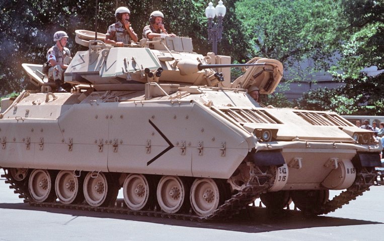
The lack of side firing ports and presence of periscopes in the rear roof hatch specify this vehicle as an M3A1. The coaxial machine gun is covered by a barrel shroud, and the large trim vane is present on the vehicle's bow. The vehicle commander is on the turret's right side, and the gunner is opposite the commander, behind the armored boxes containing the sights. The TOW missile launcher is stowed on the turret's left side. (Picture taken 8 Jun 1983 by LCPL Contreras; available from the Defense Visual Information Center.)
External stowage is detailed in this sketch. (Picture from TM 9-2350-284-10-1 C1.
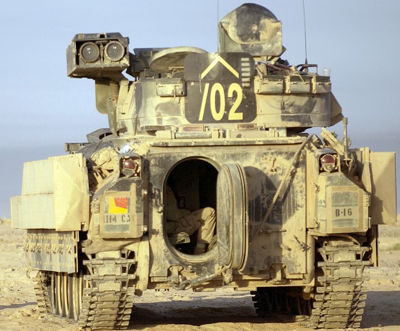
This vehicle, belonging to 2nd Squadron, 9th Cav Regiment, 3rd Brigade Combat Team, has ERA tiles fitted as well as transparent armor around the commander's position. Note that the headlights have been moved to atop the added armor. (Picture taken 30 May 2006 by SFC Russell Klika; available from the Defense Video & Imagery Distribution System.)
The open ramp access hatch allows us to see one of the scout observers sitting on the folding bench that replaced the earlier folding seats. In contrast to the M2 Bradley, there are no firing ports in the rear ramp. This vehicle also has been fitted with ERA armor boxes on top of its normal spaced armor skirts. (Picture taken 1 Oct 2004 by SSGT Shane A. Cuomo; available from the National Archives.)
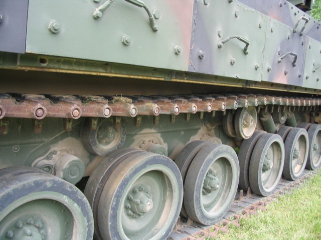
The side skirts on this vehicle have been raised, and details of the suspension are visible. The two single and one dual return rollers can be seen, as well as placement of the forward shock absorbers.
The mounting of the coaxial M240C machine gun can be seen in this view. Ejection chutes for 25mm armor-piercing (top) and high-explosive (bottom) ammunition links are visible under the machine gun.
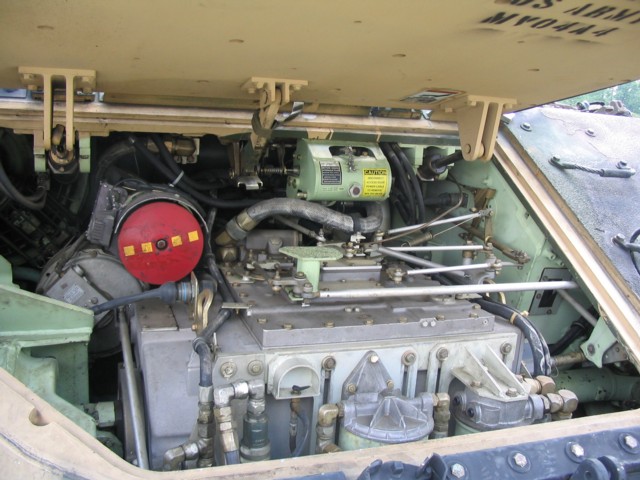
The vehicle's transmission can be seen here. The engine is behind the transmission, to the right of the driver.
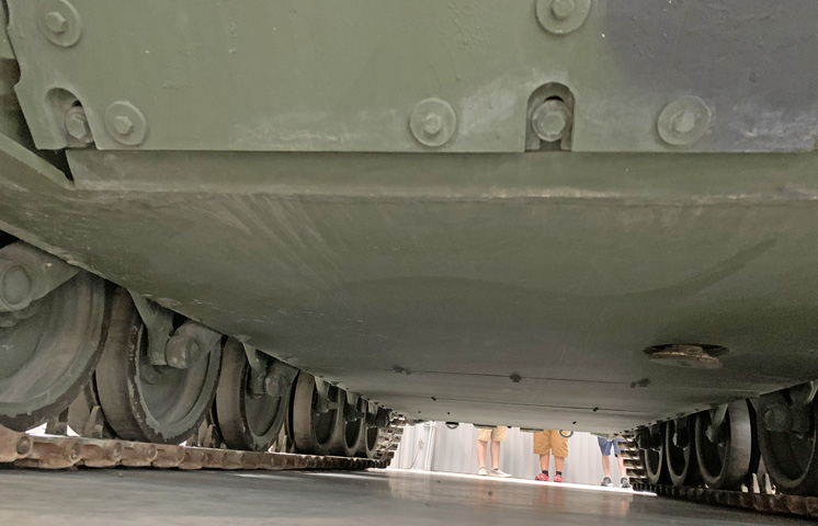
The underside of the vehicle presented a relatively smooth surface. Shock absorbers can be seen connected to the relevant road wheel arms.
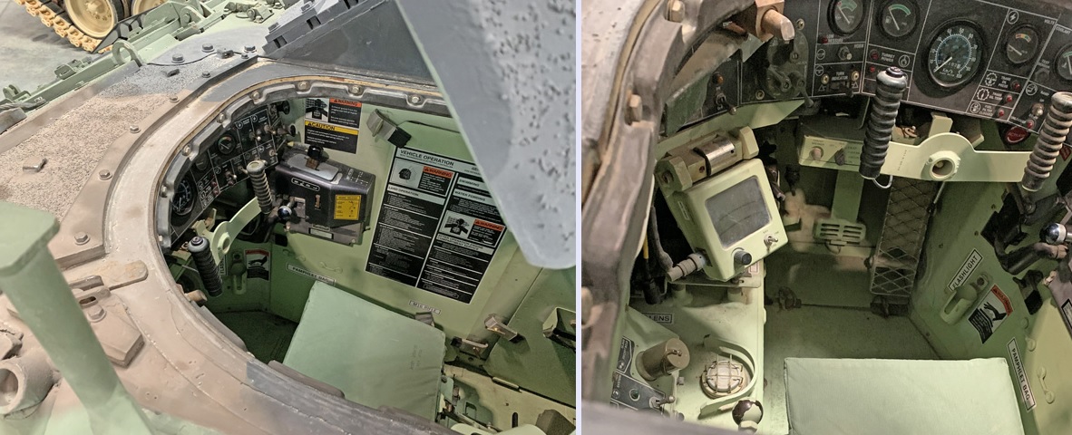
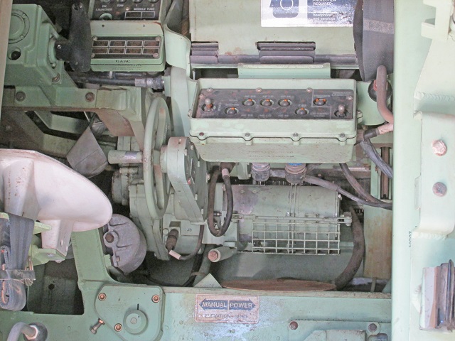
Views of the right and front sides of the driver's compartment are provided on the left and right, respectively. The steering yoke is apparent in both views, and on the left the transmission gear selector and parking brake release knob are attached to the right-side wall ahead of the engine compartment access panel. The instrument panel surrounds the driver to the front, and the large expanded-metal accelerator pedal and smaller brake pedal are visible in the right image below the steering yoke. The small tab at the end of the brake pedal is the adjuster pedal that allowed the brake pedal height to be modified to suit the driver. The distribution box is at the bottom left corner of the right picture, with the NBC system switch and indicator light at the bottom of the image and the slave receptacle just above. The slope indicator is the round instrument beside the distribution box protected by wire mesh. The screen to the driver's left was the liquid crystal display for the digital compass system, and the driver's control box for this system can be seen under the instrument panel behind the steering yoke.
The driver's seatback is reclined, and the seat height control handle is to the driver's left, with paint wearing off of the end knob.
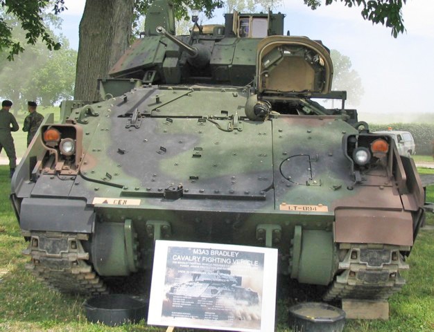
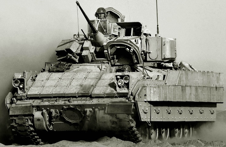
The upgraded armor first seen on the M3A2 Bradley replaced the trim vane on the front hull. The spaced armor track skirts are also visible in this head-on view. The coaxial machine gun lacks the barrel shroud present on earlier models. The driver's hatch is open on this vehicle, and the positioning of his four hatch periscopes can be seen. The commander's independent thermal viewer is mounted on the turret's right rear.
The troop compartment hatch is open on this vehicle. The four periscopes common since the M3A1 can be seen in the hatch. The CIV mount is visible on this side of the turret, and mounting points for applique passive or reactive armor are found on the vehicle's side skirts.
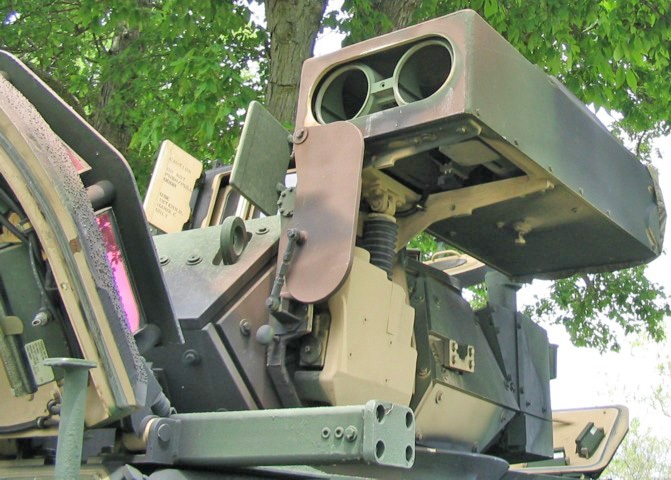
The twin TOW missile launcher is seen here raised to the firing position. The plate that covers the front of the launcher falls due to gravity when the device is raised. Details of the diver's hatch and additional turret armor can be seen. The armored flaps for the gunner's sights are also open. The drive shaft for manually raising the TOW launcher is visible with the launcher raised: it lies just to the rear and outboard of the manual lowering knob.
Further details of the erected missile launcher can be seen in this view. The launcher is normally raised electrically, and has its own elevation mechanism to give a total vertical field of fire of 48°.
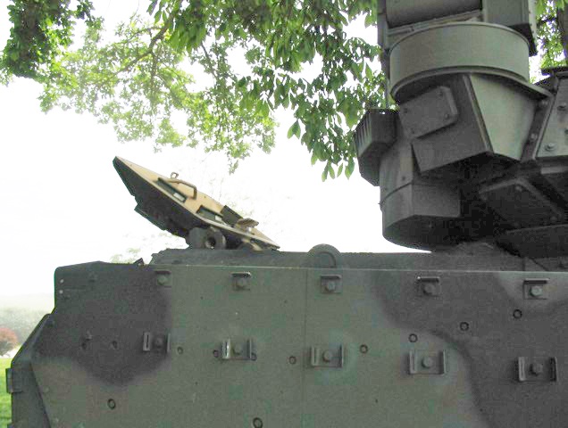
The commander's independent thermal viewer is rotated down for stowage here. When in use, this device allows the Bradley commander to search for targets while the gunner is engaging the enemy. An antenna guard is present on the side of the turret, and more details of the periscope placement in the rear hatch are visible.
A better view of the rear hatch with the integral periscopes and the CIV attachment are provided here. Note the applique armor added to the hatch as well.
This view into the troop compartment shows the results of the restowage that was intended to reduce the vehicle's vulnerability. The scouts have a bench along the left of the hull (compared with a front- and rear-facing seat in earlier vehicles). Access to the turret is visible, and the driver's position is accessible from the rear compartment via the tunnel that is formed between the turret and the left side of the hull. Access to floor ammunition stowage is also visible. The turret was segregated by a nonrotating shield with a sliding entry door for the commander and gunner. The turret would not rotate if the door was open, as in this image. Attached to the left side of the turret shield is a flat panel display that can provide passengers with the vehicle's navigational or other information.
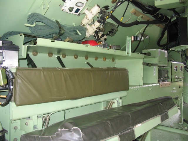
A closer view of the scouts' bench seat is presented here. A hose for air filtration is stowed above the seat, two fire extinguishers are on the upper shelf with the filtration masks, and a black clip for an M16 rifle is visible near the front of the shelf. The small tunnel to the driver's compartment can be seen to the front of the vehicle.
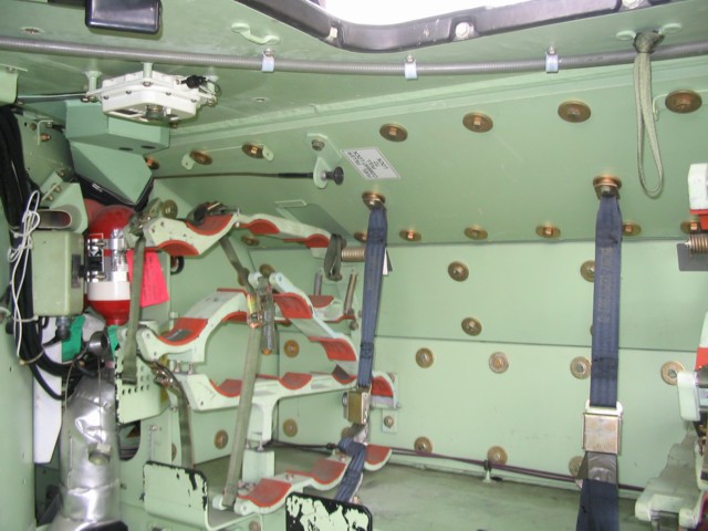
A stowage rack for TOW and Javelin antitank missiles is opposite the scouts' bench. Stowage was changed to accommodate the Javelin upon its acceptance, replacing that for the earlier Dragon missile. The label by the black knob reads: "FUEL FILLER COMBAT LOCK. PULL TO LOCK."
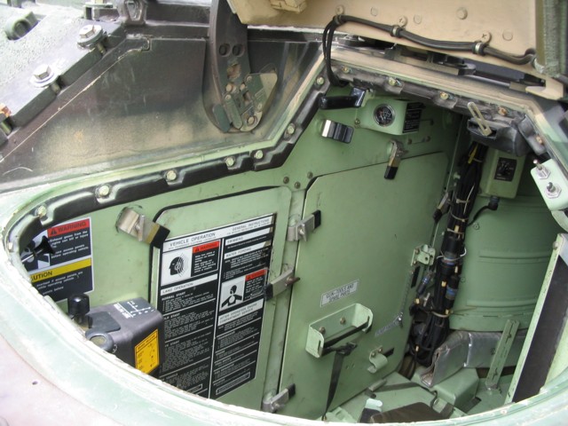
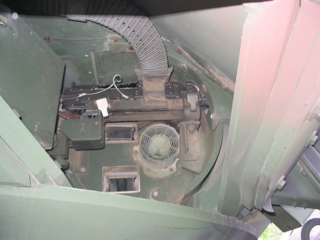
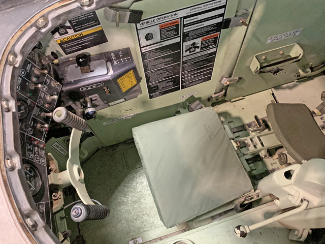
The driver's position is illustrated here, looking down into his hatch. The large door to the driver's rear contains gun tools and spare parts, and a pump handle. The large placard on the door to the driver's right contains instructions on starting the vehicle, as well as for swimming and fording water obstacles. The shift pattern is illustrated on the black shifter housing, and the yellow sticker on this housing gives instructions on the parking brake release method. The switch box placed behind the driver by the turret basket is for fan control. The additional armor protection on the hull is obvious to the right of the hatch.
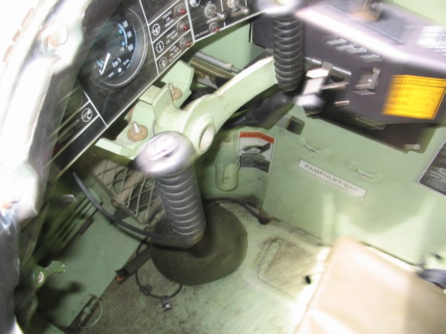
This blurry shot shows the front of the driver's compartment. The steering yoke is front and center, and the gauge above this is the speedometer. The three indicator lights to the speedometer's right warn the driver of, from top to bottom, unusual transmission oil pressure, high transmission oil temperature, and a clogged fuel filter. The transmission selector is to the right of the steering yoke, and has markings for reverse, pivot, drive, and low gear ranges. The meshed accelerator pedal is placed at the driver's right foot, the green brake pedal is to the left of the accelerator, and there is stowage for a pamphlet bag beside the driver's right leg.
The gunner's instruments and controls are visible in this picture. The gun control cadillacs are in the center of the picture, below the sighting periscope housing. The day sight of the IBAS is on the right, while the gunner's night sight is under the browpad. The black-handled knob to the right of the periscope housings is for opening the protective flaps for the sights and laser rangefinder. As illustrated on the meshed center panel, pivoting the handle down to the vertical position closes the doors. The gunner's seat is visible in the lower left of the picture, and his hatch can be seen in the turret roof. The tops of the manual traverse and elevation handwheels can be seen to the left and right, respectively, of the gun control cadillacs. A trigger was provided on the traverse handwheel.
The Bradley commander sits just to the gunner's right. The turret control box seen on the left of the picture is the same one that was to the right in the picture of the gunner's station above. The screen serves as the commander's thermal viewer, as well as information displays which can be transmitted digitally to or from other units. The commander's override handle is visible on the right side of the turret. The controls below the commander's information screen are for, left to right: stowage of the CITV; adjusting the autotrack feature and gaze size of the IBAS; adjusting the RBD display, and below this selecting whether the laser rangefinder uses the first or last return; and adjusting the mode, polarity, zoom level, etc., of the CITV. Two periscopes can be seen in the turret roof.
