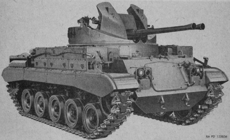
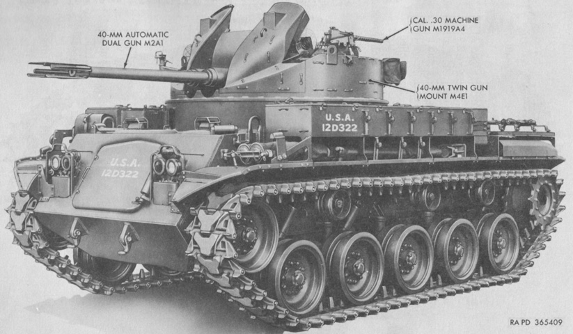
Twin 40mm Self-propelled Gun M42.
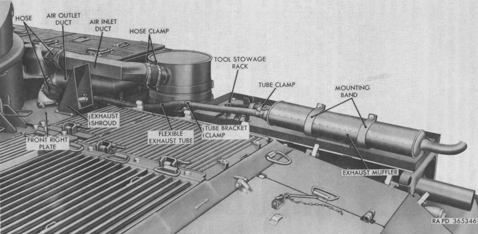
This early-production machine is fitted with the conical flash hiders on the 40mm guns as well as features common to early M41 tanks like suspension skirts and square fenders. The large door in the hull front supplemented the hull roof hatches for access to the driving compartment. Stowage and ammunition boxes are atop the right fender, and a pioneer tool stowage rack is above the right engine muffler at the rear of the fender. An empty rack for a water can is in the front of the forward stowage box. (Picture from TM 9-761A Self-propelled Twin 40-mm Gun T141.)
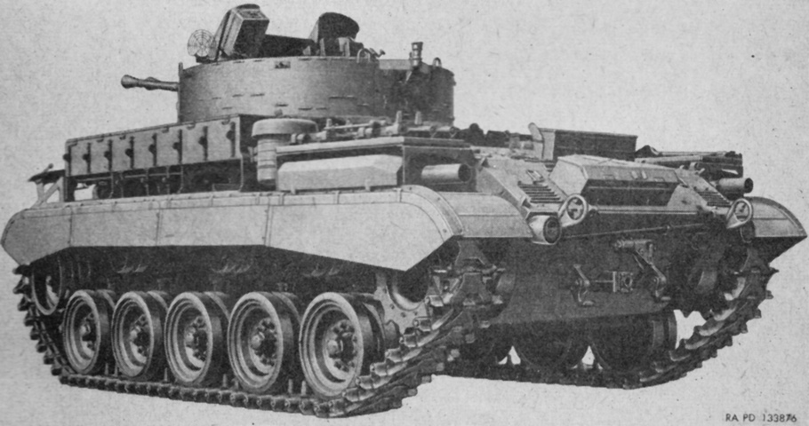
Spare track shoes were stowed above the left-side engine muffler, and the cylindrical left-hand engine air cleaner can be seen in front of the muffler. Two spare 40mm gun barrels could be stowed on the left fender ahead of the air cleaner. (Picture from TM 9-761A Self-propelled Twin 40-mm Gun T141.)
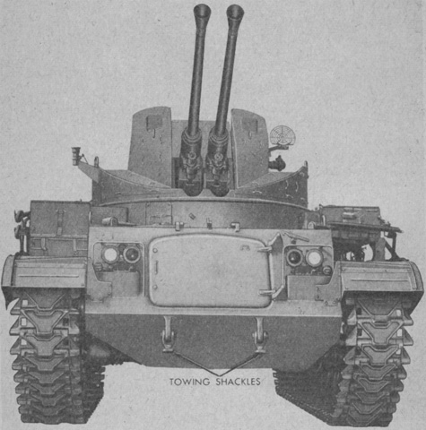
The hull front was dominated by the large door, and a machine gun pintle socket can be seen on the turret's right side. (Picture from TM 9-761A Self-propelled Twin 40-mm Gun T141.)
The towing pintle is secured in its stowage bracket, and the frames around the engine mufflers allowed for mounting the pioneer tool rack and spare track blocks above. (Picture from TM 9-761A Self-propelled Twin 40-mm Gun T141.)
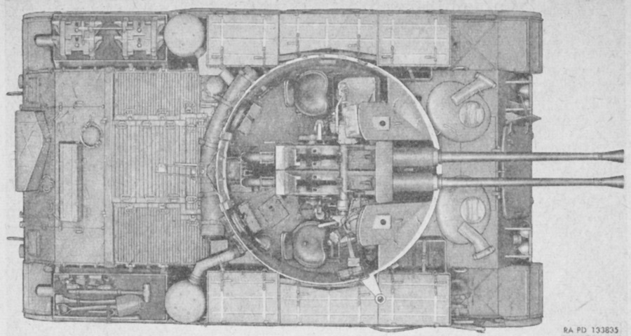
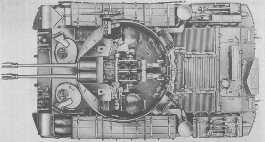
The turret interior and engine deck can be seen in this top-down view. There is no muffler for the auxiliary generator engine on this early vehicle, and the hull roof between the driver's and commander's hatches is composed of hinged doors. Note also the differing orientation of the hull roof hatches. (Picture from TM 9-761A Self-propelled Twin 40-mm Gun T141.)
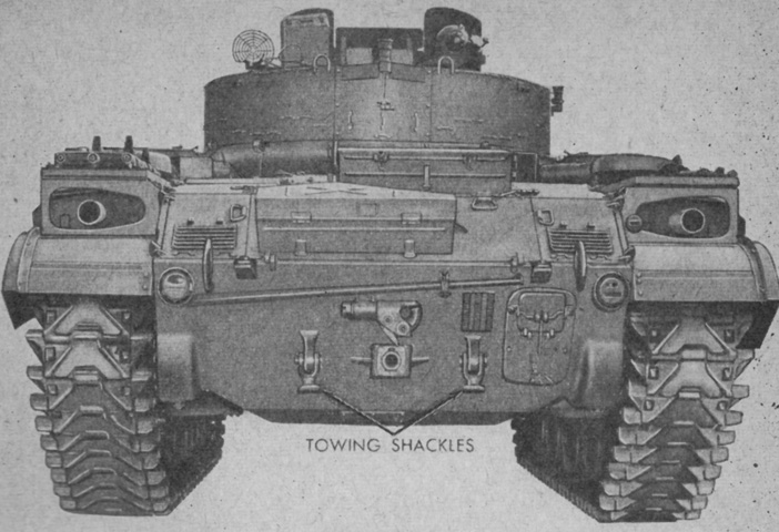
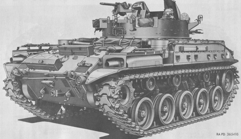
This later machine has 3-prong flash suppressors instead of the conical flash hiders, it lacks side skirts, and its fenders are angled. Spare 40mm gun barrels are in place on the left fender, and a water can is strapped down in front of the stowage boxes on the right fender. (Picture from TM 9-7218 Twin 40-mm Full Tracked Self-propelled Gun M42 (T141).)
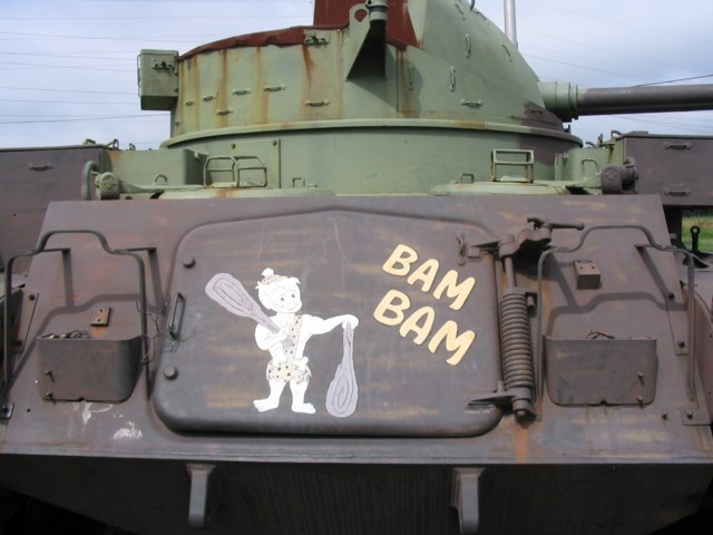
"Bam Bam's" front door is immediately obvious, with the hinge, spring, and hold-open latch on the right of the picture. The headlight mountings and guards are just outboard on both sides of the front door, and the driver's and commander's periscope guards are visible on top of their hatches.
The muffler for the auxiliary generator engine can be seen secured to the pioneer tool rack above the right main engine muffler. (Picture from TM 9-7218 Twin 40-mm Full Tracked Self-propelled Gun M42 (T141).)
The auxiliary generator engine muffler is more easily seen from above, along with the necessary rearrangement of the pioneer tools. Seats for the two loaders are also visible folded against the rear turret wall on each side of the gun mount. (Picture from TM 9-7218 Twin 40-mm Full Tracked Self-propelled Gun M42 (T141).)
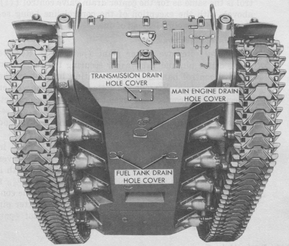
A large chute for expended 40mm ammunition cases was present in the underside of the hull. Note also the asymmetrical design of the hull inherited from the M41 tank. (Picture from TM 9-7218 Twin 40-mm Full Tracked Self-propelled Gun M42 (T141).)
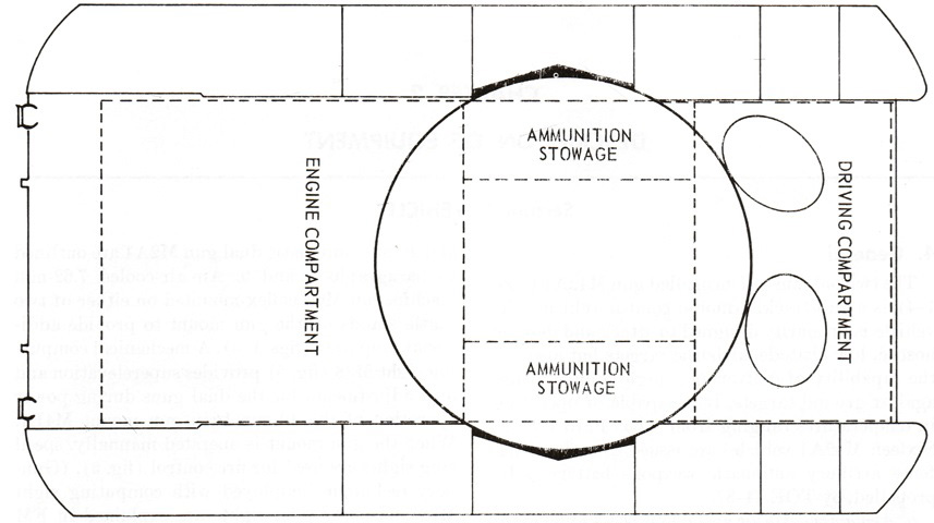
Hull compartments are labeled in this drawing. The ammunition stowage compartment served as a base for the gun mount and also provided a tunnel on each side for interior stowage of a total of 192 40mm rounds packed in twelve 16-round cans. (Picture from FM 44-61 Procedures and Drills for Twin 40-mm Self-propelled Gun M42 and M42A1.)
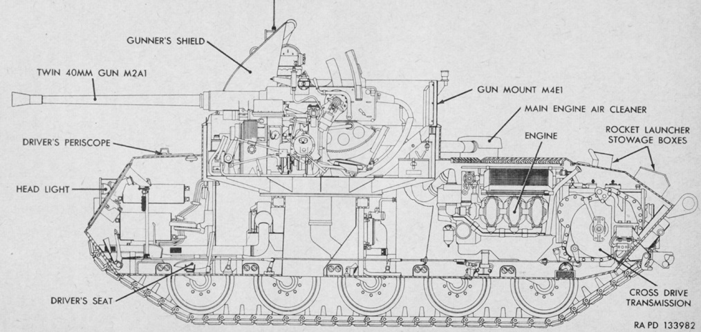
The interior layout is sketched in this cross-section. (Picture from TM 9-761A Self-propelled Twin 40-mm Gun T141.)
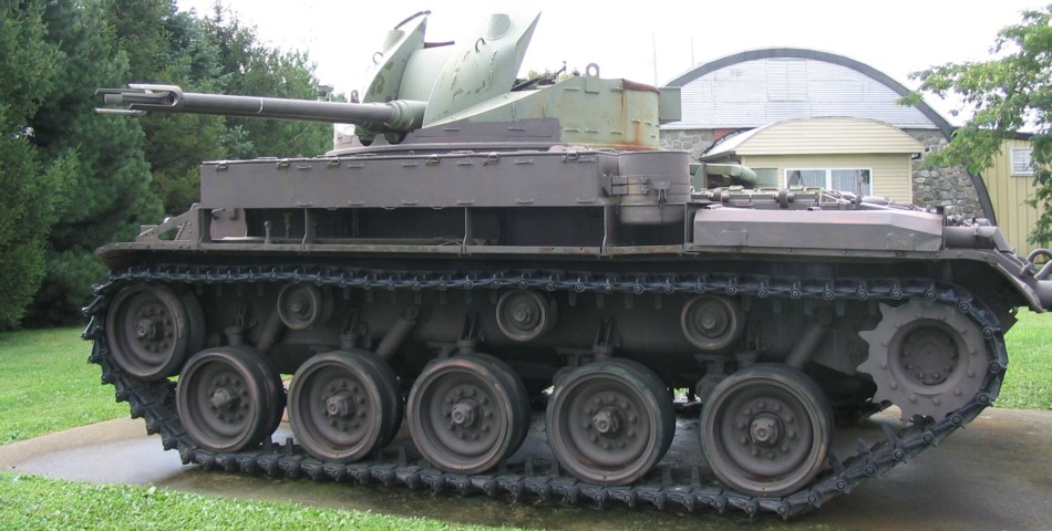
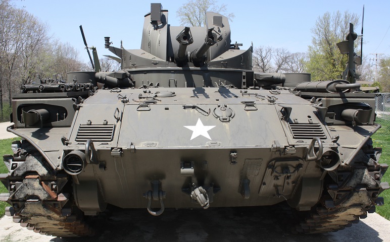
This M42 features the three-prong flash suppressors on the 40mm guns, although they lack the reinforcing ring that was introduced late in the production run. The lineage of the 76mm gun tank M41 is obvious when looking at the lower hull and running gear. Stowage and ammunition boxes are over the right fender, and two spare 40mm barrels were able to be stored under the left-side ammunition stowage boxes. The bottom portion of one of the main engine air cleaners is mounted just behind the rear fender stowage box, and one of the main engine mufflers is on top of the rear of the fender.
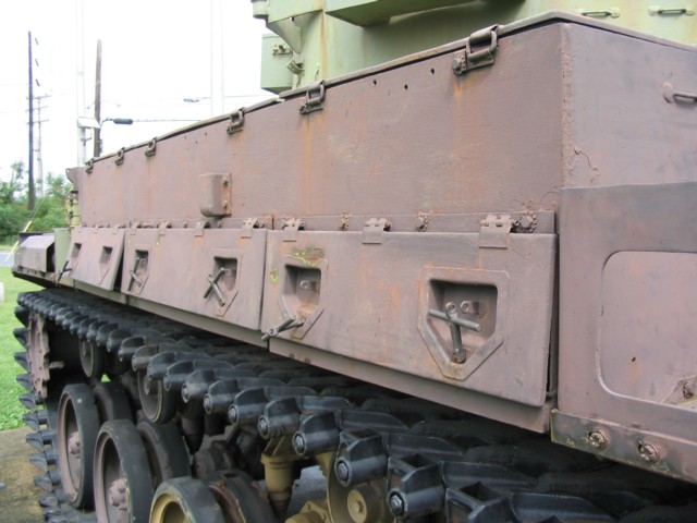
Stowage boxes line the vehicle's right fender. Details of the suspension, including the volute spring bumper stops, can be seen at the bottom of the picture. The rear turret machine gun mount is at the very top of the photo.
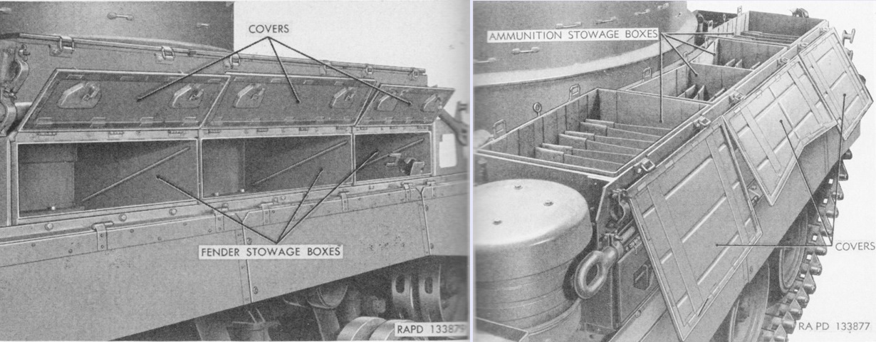
The stowage boxes are opened on the left. The front box contained retainers for a spare machine gun barrel as well as an oil can bracket, the latter of which can be seen at the lower front corner of the box. Three ammunition stowage boxes were present on each side of the vehicle, and the right trio are seen in the right image. The center boxes were interchangeable only with each other, while the other four boxes were all the same. Each of the boxes could stow ten 4-round clips, for a total of 240 rounds. (Picture from TM 9-761A Self-propelled Twin 40-mm Gun T141.)
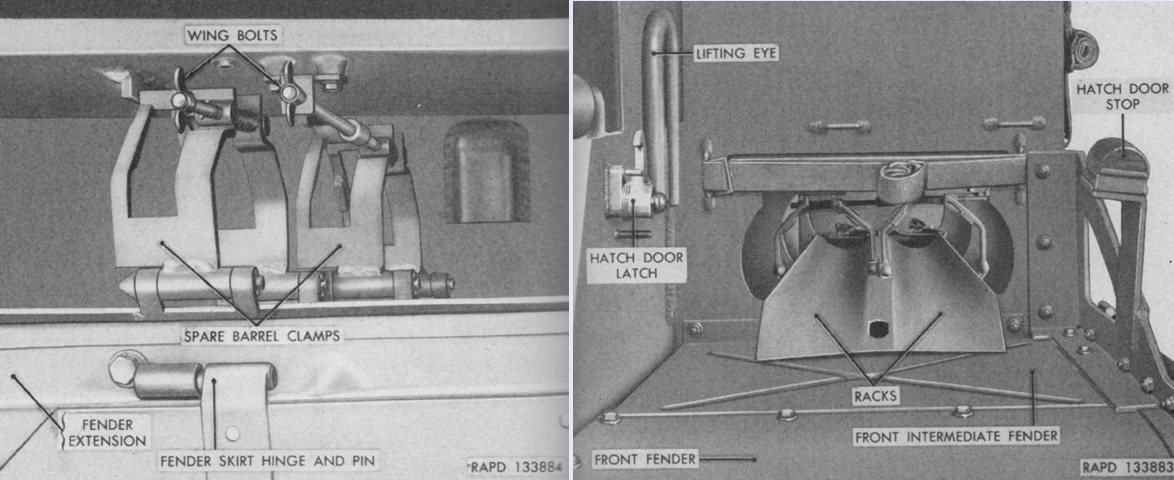
The spare 40mm gun barrel stowage is seen on the left fender of an early vehicle. After muzzle and breech covers were secured to the barrels, the barrels were to be slid muzzle-first into the stowage rack until the muzzle was firmly against the end bracket. The muzzle ends were then secured with retaining straps and the breech end with the spare barrel clamps seen on the left. (Picture from TM 9-761A Self-propelled Twin 40-mm Gun T141.)
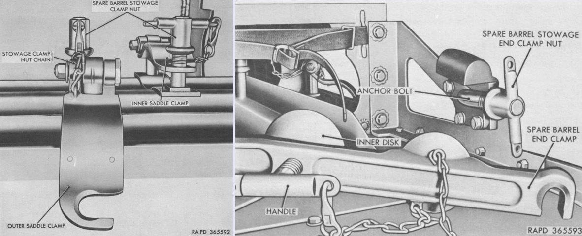
Later vehicles changed the design of the spare barrel clamps to inner and outer saddle clamps and also added a spare barrel end clamp. Straps over the muzzles were retained. (Picture from TM 9-7218 Twin 40-mm Full Tracked Self-propelled Gun M42 (T141).)
This shot shows the spare barrel rack over the left fender. The fender itself is angled to a point like those on later-production M41 Walker Bulldogs.
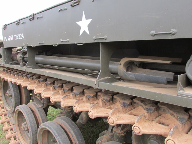
This vehicle has spare barrels in place on the fender. The barrel could be changed in about 3 minutes.
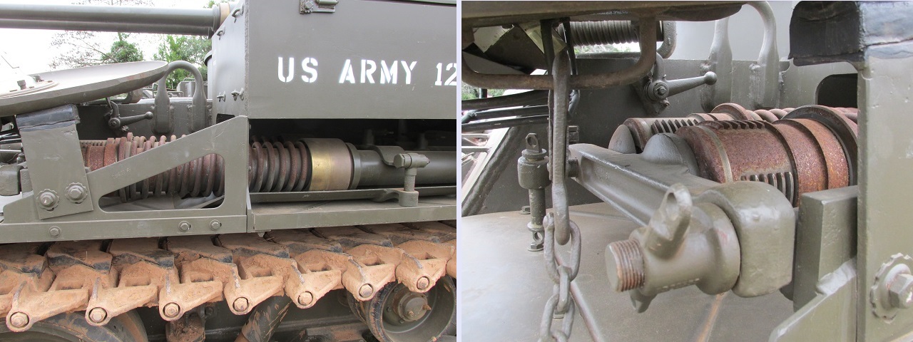
The extra barrels were stowed with their rear to the front of the vehicle. The recuperator springs can be seen around the end of the barrels. The spare barrel end clamp is detailed in the right image.
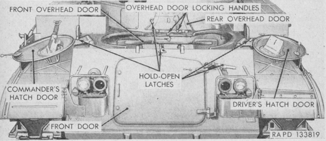
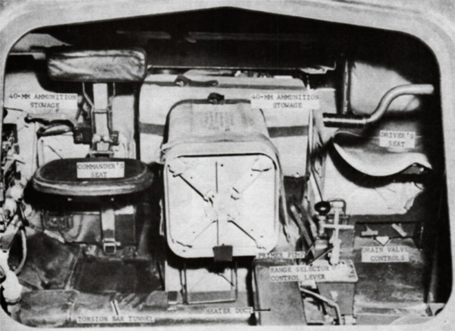
The early overhead doors of the drivers' compartment are shown here in the open position. These allowed ammunition to easily be passed from the hull to the turret. (Picture from TM 9-761A Self-propelled Twin 40-mm Gun T141.)
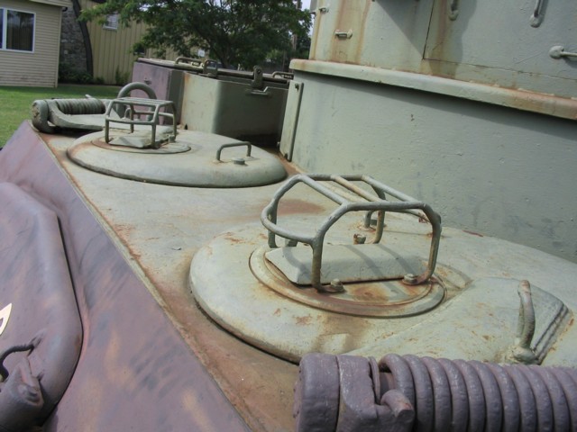
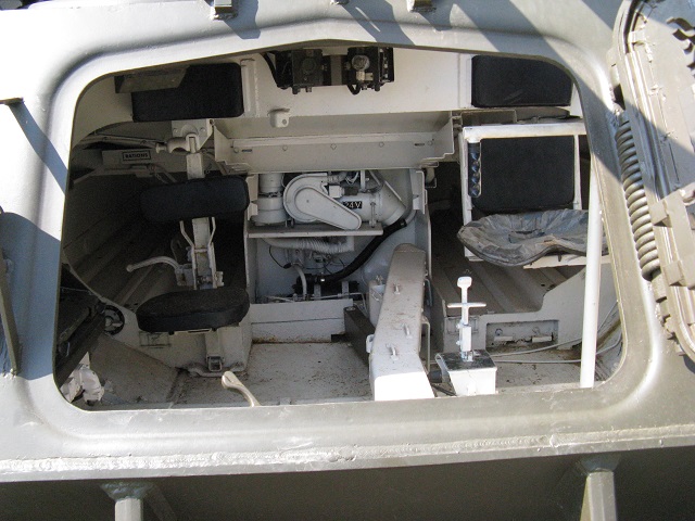
The vehicle commander occupied the seat in the hull front right, and the driver sat beside him. This later-production vehicle does not feature the hull overhead doors.
The front door of an early vehicle with overhead roof doors is shown here closed on the left and open on the right. On early vehicles, the front door had provisions for mounting a .30cal ammunition box and either two .30cal carbines M2 or an M2 carbine and a .45cal submachine gun. (Picture from TM 9-761A Self-propelled Twin 40-mm Gun T141.)
Stowage on the front door was changed on later vehicles to include the stowage box for the driver's infrared periscope M19, a flashlight retaining bracket, and the .30cal ammunition box. (Picture from TM 9-7218 Twin 40-mm Full Tracked Self-propelled Gun M42 (T141).)
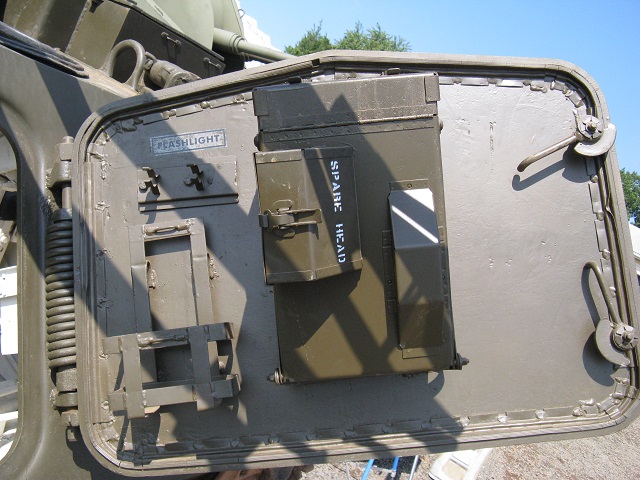
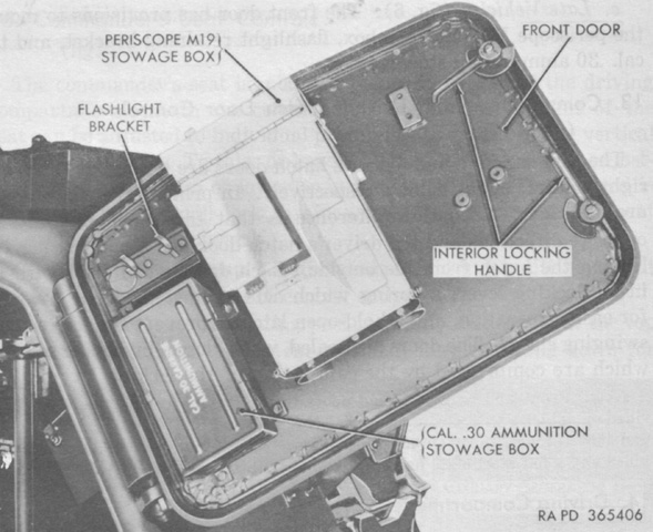
The inside of the front door is illustrated here. Flashlight and periscope head stowage is labeled, and two interior locking handles are on the far end of the door.
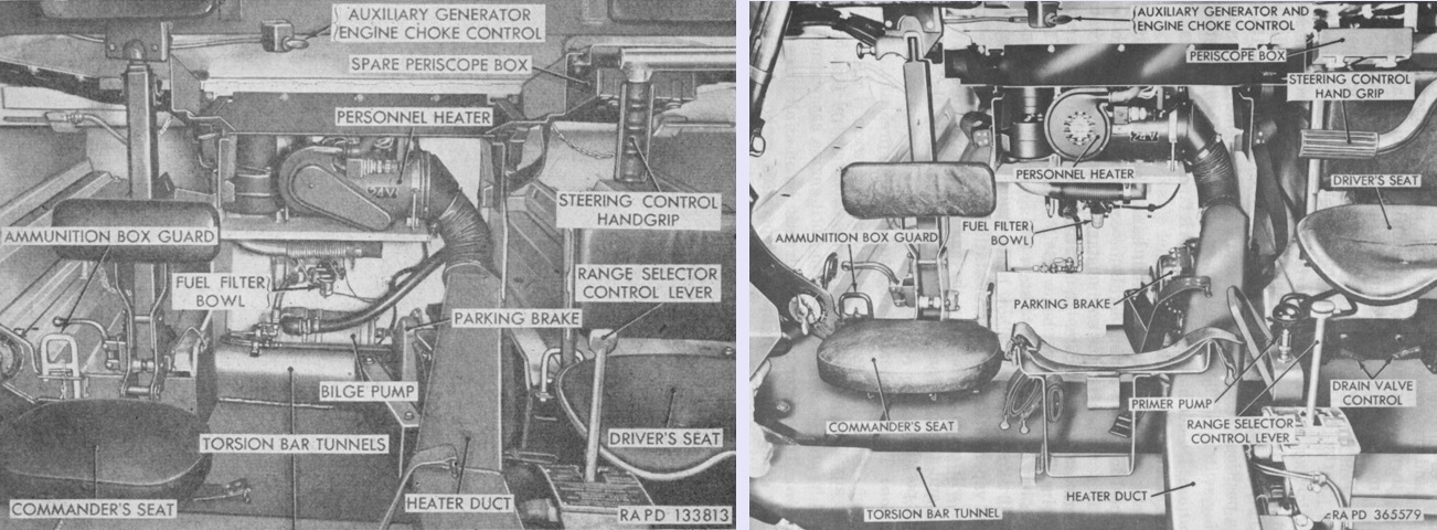
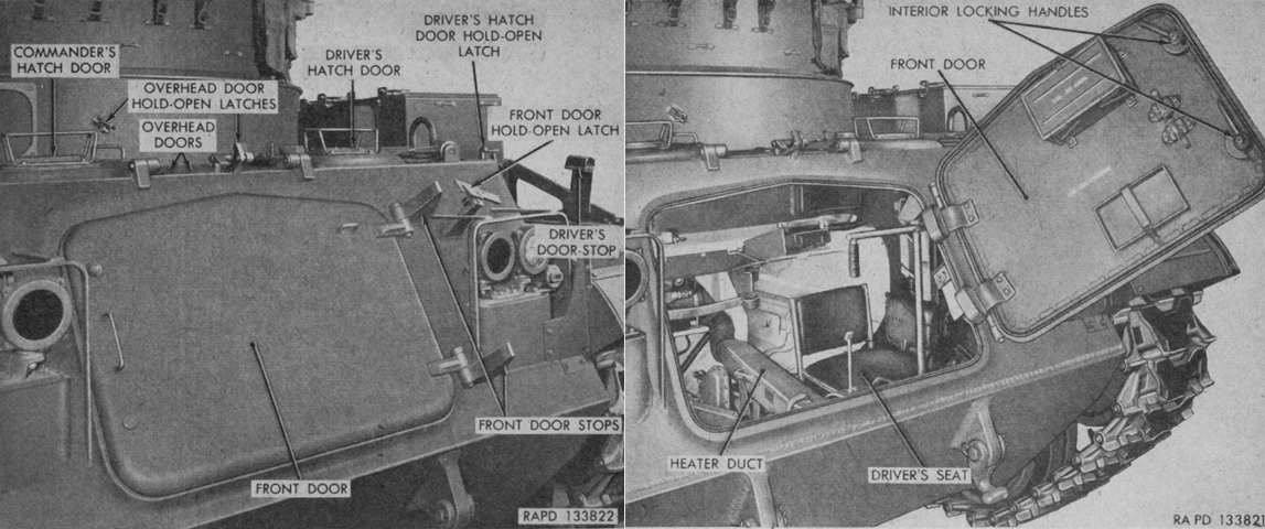
An overview of the driver's compartment can be compared between an early vehicle on the left and a later one on the right. (Picture from TM 9-761A Self-propelled Twin 40-mm Gun T141 and TM 9-7218 Twin 40-mm Full Tracked Self-propelled Gun M42 (T141).)
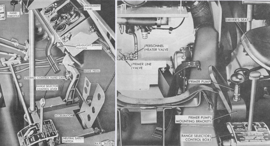
Peering through the open front door, we are able to see the positions for the driver and commander. The personnel heater can be seen towards the center of the vehicle, and a heater duct snakes along the floor between the driver and commander. The heater used gasoline as fuel and had a rated capacity of 20,000 Btu per hour at ¼-gallon (.95L) of gasoline per hour or 10,000 Btu per hour at ⅛-gallon (.473L) of gasoline per hour.
Three more 16-round 40mm ammunition cans could be strapped down between the driver and commander. (Picture from FM 44-61 Procedures and Drills for Twin 40-mm Self-propelled Gun M42 and M42A1.)
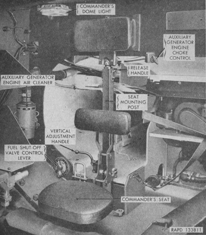
The vehicle commander, also referred to as the section leader, sat at the right front of the hull. A radio rack was to his right, and he normally also acted as radio operator. (Picture from TM 9-761A Self-propelled Twin 40-mm Gun T141.)
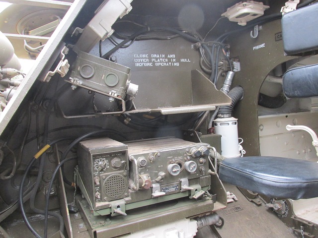
The commander's position and radio racks are shown here.
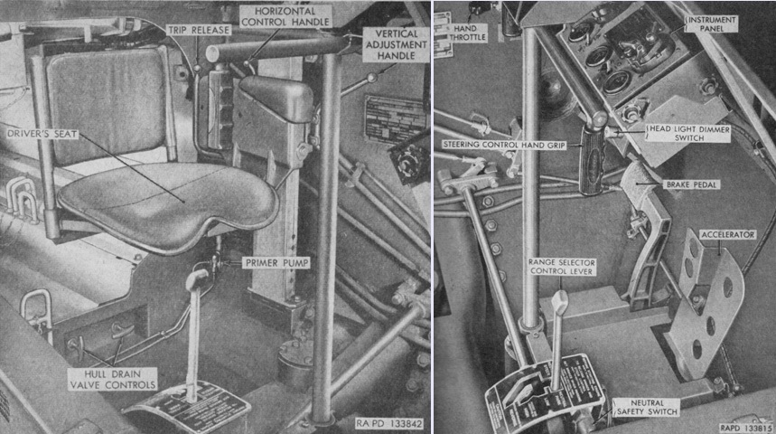
Two views of the driver's position of an early vehicle are seen here. The neutral safety switch would not let the engine start unless the range selector control knob was in the neutral park position. (Picture from TM 9-761A Self-propelled Twin 40-mm Gun T141.)
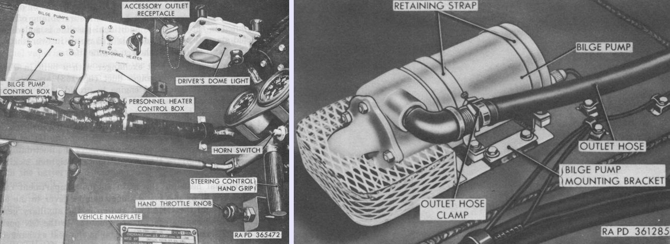
Vehicles with Ordnance serial numbers 1-661, 1205-1354, and 1555-1626 were equipped with two 50 gallon/minute (190L/min) bilge pumps, one in the driving compartment and the second in the engine compartment. The engine compartment bilge pump is shown on the right. The pump intakes were protected by a mesh screen ½" (1.3cm) above the floor, and the control box for the bilge pumps was to the driver's left adjacent to the control box for the personnel heater. In vehicles built without bilge pumps, the control box was eliminated. The torsion bar tunnels had slots along the floor line to allow water to drain to the lowest point in the hull, and any water below the bilge pump pick-up level could be drained through the three hull floor drain valves. (Picture from TM 9-7218 Twin 40-mm Full Tracked Self-propelled Gun M42 (T141).)
A later-production driver's position is illustrated in these images. Notably, the location of the primer pump was changed to his right side, and the shape of the steering control handgrip was modified. (Picture from TM 9-7218 Twin 40-mm Full Tracked Self-propelled Gun M42 (T141).)
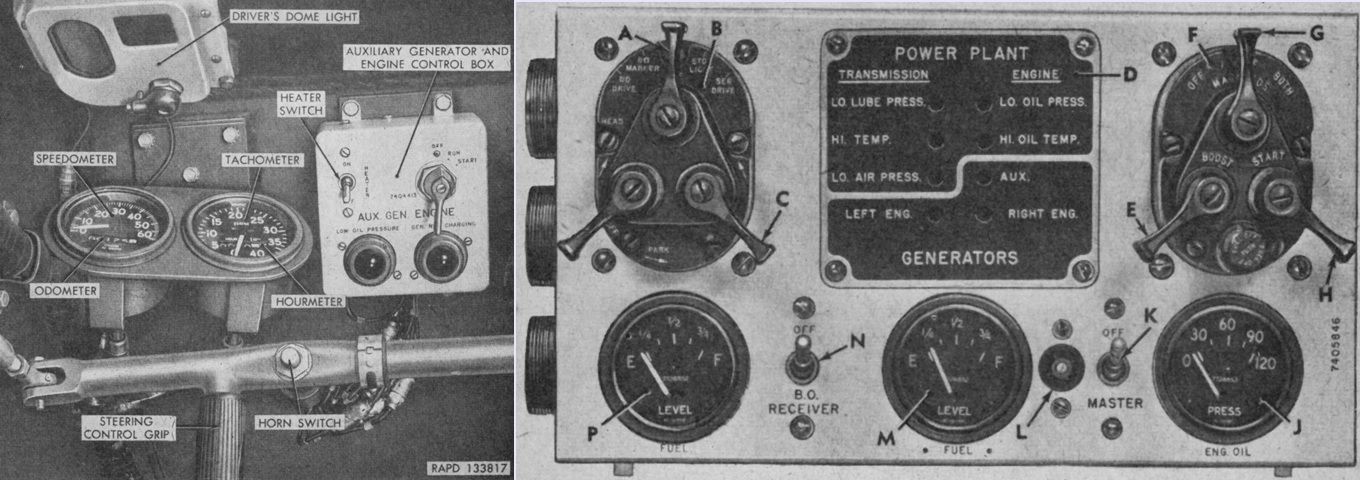
The speedometer and tachometer were to the driver's front, and his instrument panel is show on the right. This is an early-production vehicle. A. Main light switch. B. Lighting switch assembly. C. Safety switch. D. Warning light panel. E. Main engine booster switch. F. Starter switch assembly. G. Main engine magneto switch. H. Main engine starter switch. J. Engine oil pressure gage. K. Master relay switch. L. Master relay indicator light. M. Right fuel tank gage. N. Blackout receiver switch. P. Left fuel tank gage. (Picture from TM 9-761A Self-propelled Twin 40-mm Gun T141.)
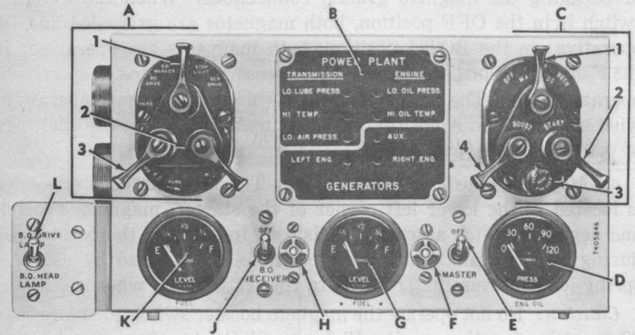
A later-production driver's instrument panel is labeled in this picture. In early vehicles, the blackout headlights were operated when the main light switch was moved to the BO DRIVE position. Later machines had a toggle switch added to the instrument panel that selected either the blackout drive lamps or blackout headlamps when the main light switch was in the BO DRIVE position. A. Light switch assy. 1. Main light switch. 2. Safety switch. 3. Inoperative switch. B. Warning light panel. C. Starter, magneto, booster, and degasser switch assy. 1. Magneto switch. 2. Starter switch. 3. Degasser switch (fuel cutoff). 4. Magneto booster switch. D. Engine oil pressure gage. E. Master relay switch. F. Master relay switch indicator light. G. Right fuel tank gage. H. High beam indicator light. J. Blackout receiver switch. K. Left fuel tank gage. L. Blackout selector switch. (Picture from TM 9-7218 Twin 40-mm Full Tracked Self-propelled Gun M42 (T141).)
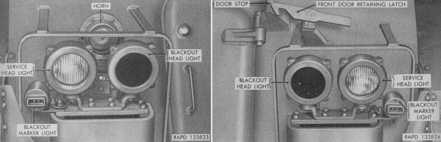
The right and left headlight clusters of an early vehicle are shown on the left and right, respectively. The blackout headlights were used in conjunction with blackout viewers after the blackout receiver switch on the driver's instrument panel had been turned on. (Picture from TM 9-761A Self-propelled Twin 40-mm Gun T141.)
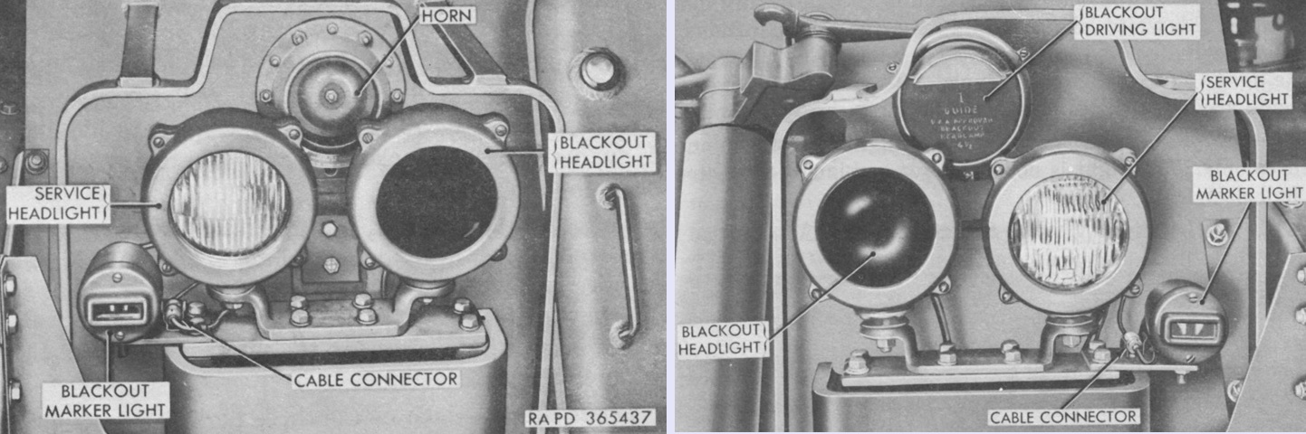
The headlights of a later-production machine differed by the addition of a blackout driving light that was used for partial blackout operations. (Picture from TM 9-7218 Twin 40-mm Full Tracked Self-propelled Gun M42 (T141).)
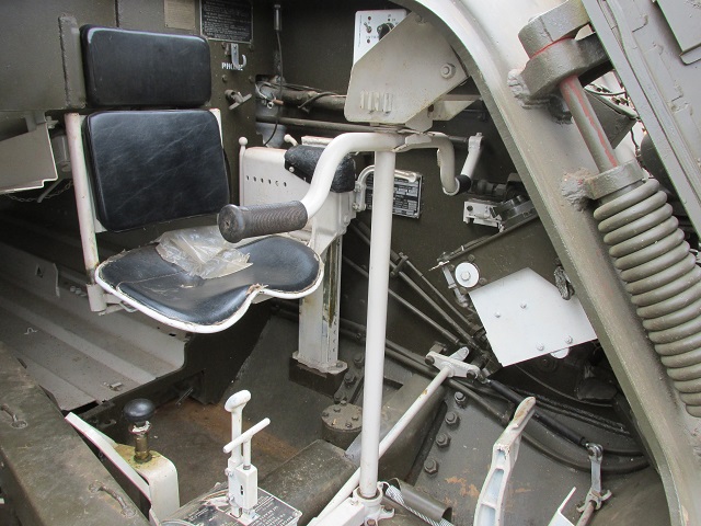
The driver's position is detailed here. His steering control crossbar is placed directly in front of his seat, and his legs would reach around the vertical post to the foot pedals. The white transmission range selector control lever is placed in front of and to the right of the driver, and the black handle to the rear of the transmission range selector is the primer pump. The internal handle to activate the fixed fire extinguisher system is somewhat limply hanging from the bulkhead below the hanger hook.
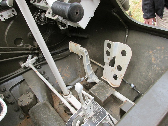
The large perforated pedal is the accelerator, while the smaller pedal to its left is the brake. A tunnel for the front set of torsion bars can be seen running crosswise along the floor, and the mounting point for the idler wheel can be discerned on the hull side.
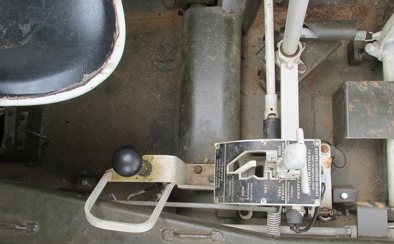
The transmission range selector is detailed here. There are selections for reverse, low, high, neutral steer, and neutral park. The range selector was sprung so that it would return to neutral park from neutral steer once it was released; a neutral turn required holding the selector in position.
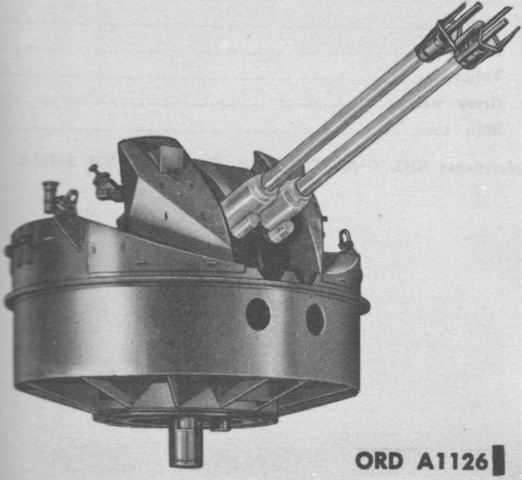
The twin 40mm gun mount M4E1 is shown dismounted from the hull. It weighed ~6,300lb (~2,900kg) complete with the guns. (Picture from TM 9-500 C3 Data Sheets for Ordnance Type Materiel.)
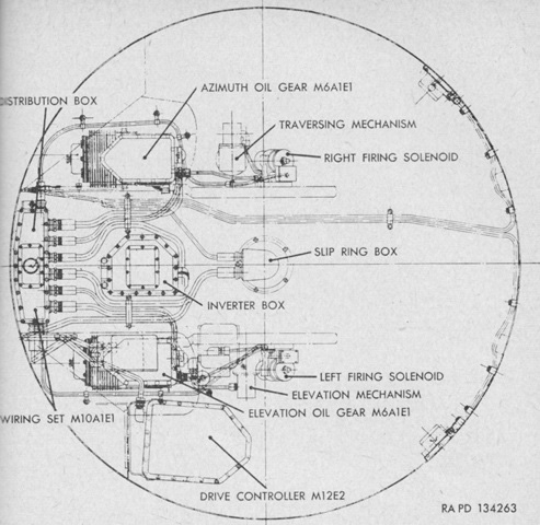
A schematic of the local control system M16A1E1 is given in this image. The oil gears drove the guns in elevation and azimuth. Electric motors drove oil pumps whose output, controlled by electric signals from the drive controller, went directly to the hydraulic motors which drove the gun mount. Components of the wiring set M10A1E1 included the inverter, which converted 24 volt direct current from the vehicle power supply to the 115 volt, 60 cycle, single phase, alternating current which controlled the output of the oil pumps; the distribution box, which contained terminal boards to which were connected the the 24 volt vehicle power supply, 115 volt inverter power supply, and telephone circuits; slip ring box, which fed the 24 volt vehicle power supply and telephone circuits from the hull to the gun mount via brush contacts; and the drive controller M12E2, which controlled the rate and direction of gun movement as well as firing of the guns via electrical triggers. (Picture from TM 9-761A Self-propelled Twin 40-mm Gun T141.)
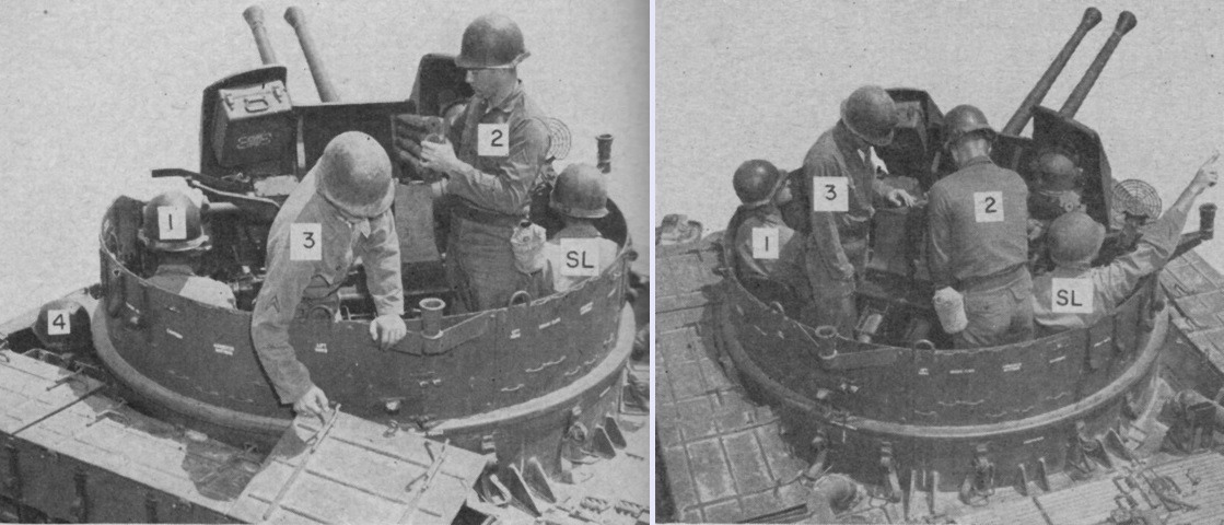
The turret crew is shown in position when loading the 40mm guns on the left and when preparing to engage an aerial target on the right. SL is the lead setter, referred to here as squad leader; 1 is the gun pointer or gunner; 2 and 3 are the right and left loaders or cannoneers, respectively; and 4 is the driver. (Picture from FM 44-61 Self-propelled Twin 40-mm Gun T141.)
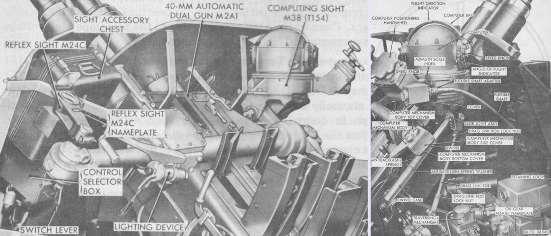
The computing sight M38 is seen installed on the left, and the computer controls are labeled in the right image. The control selector box contained a two-position rotary switch with LOCAL and REMOTE positions. The LOCAL position caused electrical signals originating in the vehicle's own drive controller M12E2 to be delivered to the oil gears. The REMOTE position allowed a remote control director to control the operation of the oil gears via receptacles at the hull rear. The control selector box was omitted after vehicle Ordnance serial no.1877. (Picture from TM 9-7218 Twin 40-mm Full Tracked Self-propelled Gun M42 (T141).)
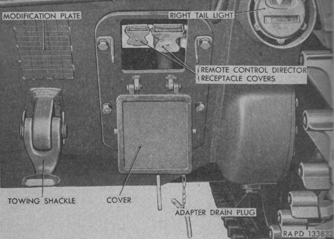
The receptacles for connection to the the remote fire control director unit were located at the right rear of the hull. (Picture from TM 9-761A Self-propelled Twin 40-mm Gun T141.)
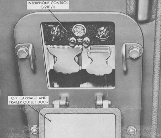
The interphone control C-981/U was found under the same waterproof door as the remote fire control director receptacles. (Picture from TM 9-7218 Twin 40-mm Full Tracked Self-propelled Gun M42 (T141).)
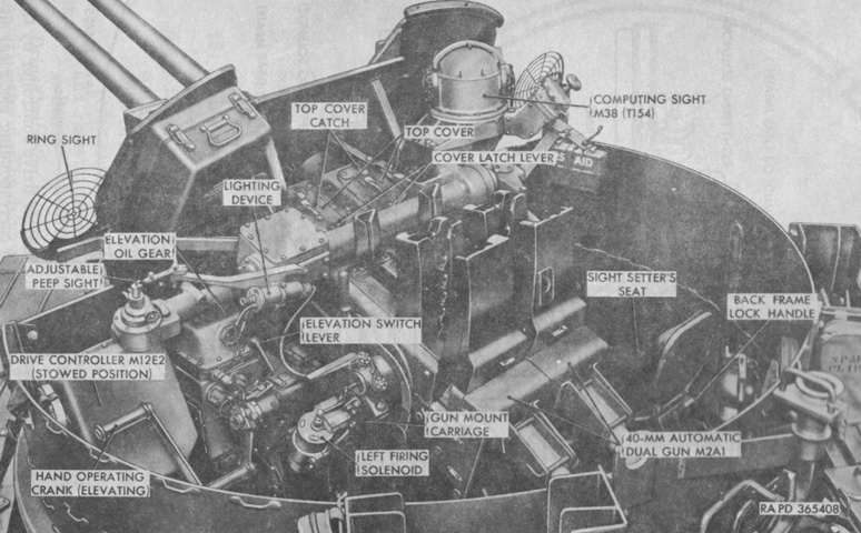
Armament, sighting, and fire control materiel are highlighted in this picture. (Picture from TM 9-7218 Twin 40-mm Full Tracked Self-propelled Gun M42 (T141).)
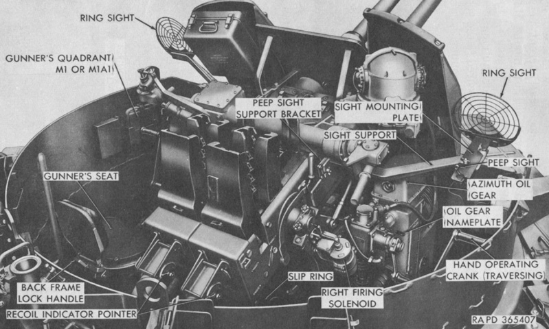
The opposite side of the gun mount is labeled here. (Picture from TM 9-7218 Twin 40-mm Full Tracked Self-propelled Gun M42 (T141).)
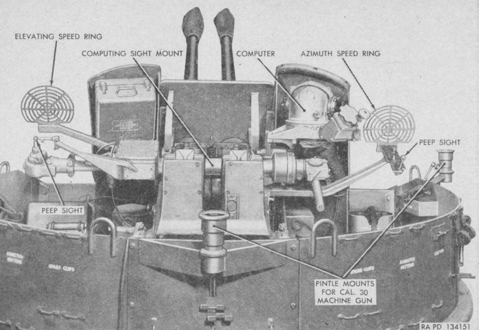
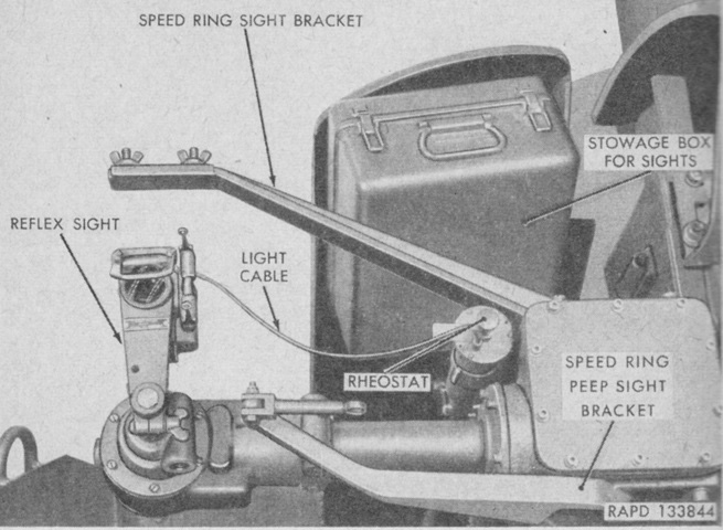
Some of the sighting and fire control equipment is labeled in this picture. The speed ring sights were for use when manually operating the gun mount, while the computer was for use with powered operation. The elevating speed ring was permanently mounted, and folded away when the reflex sight was used. The azimuth speed ring, on the other hand, was normally stowed in the sight case and only assembled when needed along with its peep sight and holder. The speed rings were composed of seven concentric rings that were calibrated for the lead required for target speeds of 100 to 700mph (160 to 1,100kph) in 100mph (160kph) increments. (Picture from TM 9-761A Self-propelled Twin 40-mm Gun T141.)
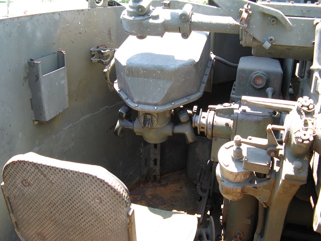
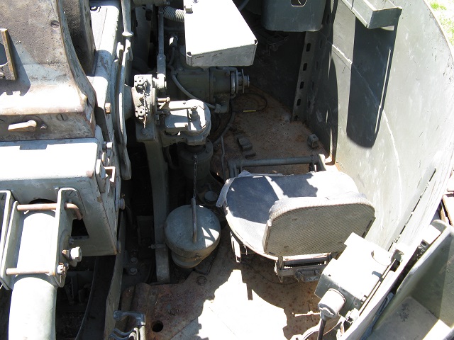
The gunner's position is shown here, with his control handles in front of his seat. The left firing solenoid can be seen inboard of where his right shoulder would be positioned; just in front of this is the attachment base for the hand elevating crank, and the elevation oil gear is toward the front of the turret.
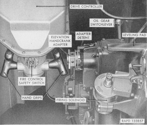
Parts of the drive controller are labeled here. The fire control safety switch needed to be turned on before the triggers on the opposite side of the hand grips would work. (Picture from TM 9-761A Self-propelled Twin 40-mm Gun T141.)
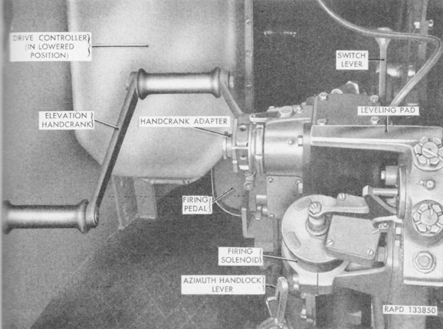
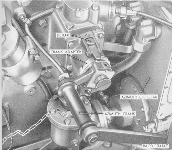
The manual elevation handcrank is shown here installed. The drive controller could be lowered out of the way when not needed; note the foot firing pedal that was used when operating in manual mode. (Picture from TM 9-761A Self-propelled Twin 40-mm Gun T141.)
This is the sight setter's position opposite the gunner. The right firing solenoid can be seen near the position of his left shoulder, and ahead of him is the attachment for the hand traverse crank.
The manual traverse handcrank is shown here installed; during manual operation the sight setter controlled the gun mount in traverse, while the gunner handled elevation and fired the guns with the mechanical foot pedal. (Picture from TM 9-761A Self-propelled Twin 40-mm Gun T141.)
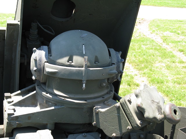
The computing sight M38 was mounted behind the sight setter's shield at the turret front.
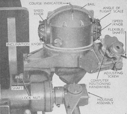
The computing sight mount was comprised of a support tube with the computer assembly on the right and the reflex sight support on the left. Handwheels were used to input the target's estimated course and speed, and the computer converted this data into leads for the guns. The results of the computations were transmitted through the housing assembly by motion of a telescoping shaft, which was resolved into drive bands which positioned the reflex sight with the proper amount of lead. The speed knobs were scaled from 0 to 700mph (0 to 1,100kph) in increments of 20mph (30kph). The angle of flight scale read from -85° to +60°. Azimuth, or angle of approach, was inputted by the computer positioning handwheel, which was graduated in increments of 800 mils. (Picture from TM 9-761A Self-propelled Twin 40-mm Gun T141.)
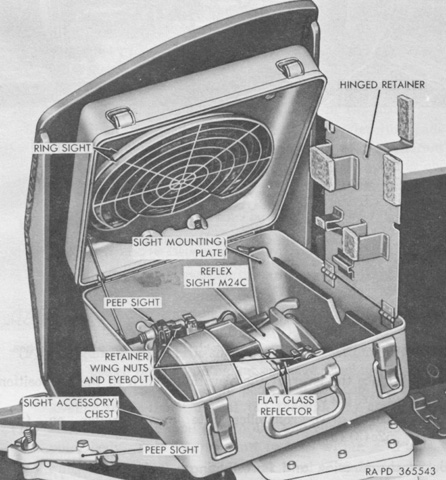
The stowage arrangement in the sight accessory chest on the gunner's shield is shown in this image. (Picture from TM 9-7218 Twin 40-mm Full Tracked Self-propelled Gun M42 (T141).)
The reflex sight M24C was able to be illuminated at night or in poor light by the light cable; the light's brightness was adjusted by the rheostat. Peep sights were provided to help with sight alignment with the target, and these could be swung out of the way when not in use. The crosshairs of the reflex sight were intended to be kept on the target, with adjustments being fed to the sight alignment via the target direction and speed data entered into the computing sight. (Picture from TM 9-761A Self-propelled Twin 40-mm Gun T141.)
The reflex sight M24C is viewed from the left in this image. (Picture from TM 9-761A Self-propelled Twin 40-mm Gun T141.)
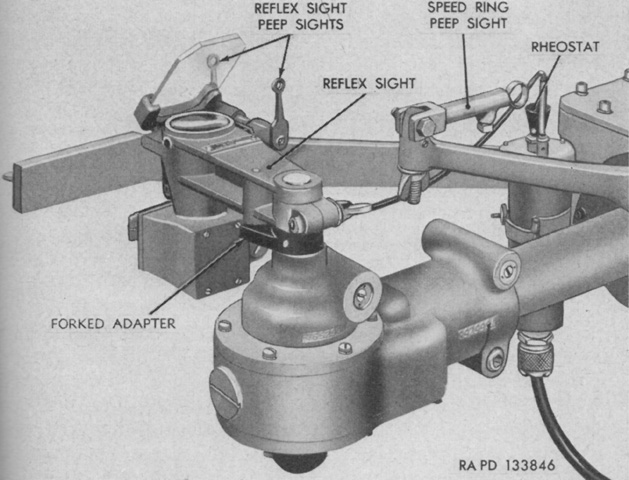
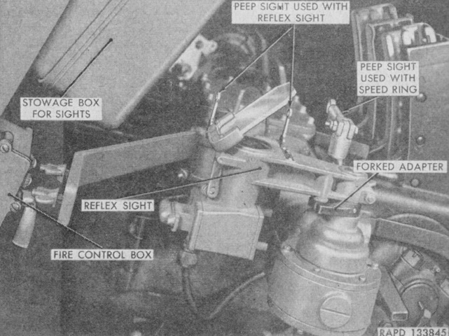
The reflex sight and its peep sights are mounted, and the speed ring peep sight is folded out of the way. (Picture from TM 9-761A Self-propelled Twin 40-mm Gun T141.)
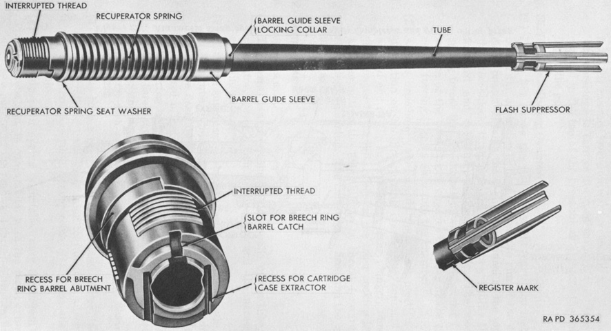
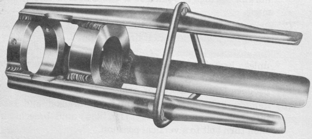
Details of the 40mm gun barrel and three-prong flash suppressor are illustrated here. The register mark on the centerline of the bottom of the barrel behind the flash hider assisted in aligning the barrel assembly during installation and removal. The dual automatic gun M2A1 weighed 2,000lb (910kg) without the mount or accessories, and each barrel weighed 296lb (134kg). With the flash suppressor, the barrel was 8'6" (259cm) long, and the complete gun was 12' (366cm) long overall. (Picture from TM 9-7218 Twin 40-mm Full Tracked Self-propelled Gun M42 (T141).)
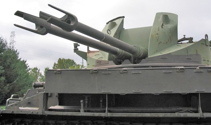
The three-prong flash suppressors that replaced the early conical flash hiders are mounted on this vehicle. The mount for the .30cal machine gun can be seen on the turret at the left of the picture, and peeking out from behind the gun shield to the right of the picture is the mount for the gunner's ring sight. Just above the lifting eyes on the gunner's shields are openings for radio antenna mounts.
The flash suppressors had begun being modified by the addition of a reinforcing ring by 21 May 1957. (Picture from TM 9-7218 Twin 40-mm Full Tracked Self-propelled Gun M42 (T141).)
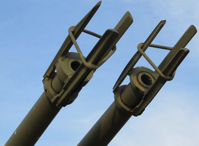
An installed view of the flash suppressors with reinforcing rings is provided here.
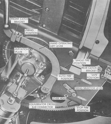
Each of the dual 40mm guns was provided with a hand operating lever to prepare it for firing. Moving the lever to the rear opened the breech, cocked the firing assembly and rammer shoe, and released the ammunition feed rollers. In case of a misfire, the same lever was used to recock the gun and remove the complete round. The lever could be held to the rear in a SAFE bracket when needed. The firing selector lever behind the hand operating lever had positions for STOP FIRE, SINGLE FIRE, and AUTO FIRE. (Picture from TM 9-7218 Twin 40-mm Full Tracked Self-propelled Gun M42 (T141).)
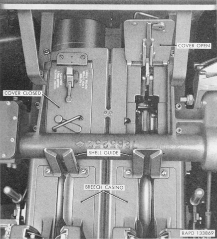
The top covers of the 40mm guns are shown here, closed on the left and open on the right. (Picture from TM 9-761A Self-propelled Twin 40-mm Gun T141.)
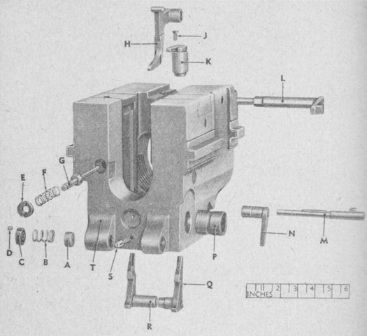
An exploded view of a breech ring is provided in this diagram. A. Loading tray bolt spring sleeve. B. Loading tray bolt spring. C. Loading tray bolt spring seat. D. Spring seat set screw. E. Safety plunger spring seat. F. Safety plunger spring. G. Breech ring safety plunger. H. Breech ring barrel catch. J. Flat-head screw. K. Breech ring barrel abutment. L. Barrel catch control arm. M. Extractor spindle. N. Extractor spindle arm. P. Breech ring crankshaft collar. Q. Right extractor. R. Left extractor. S. Crankshaft collar screw. T. Breech ring. (Picture from TM 9-761A Self-propelled Twin 40-mm Gun T141.)
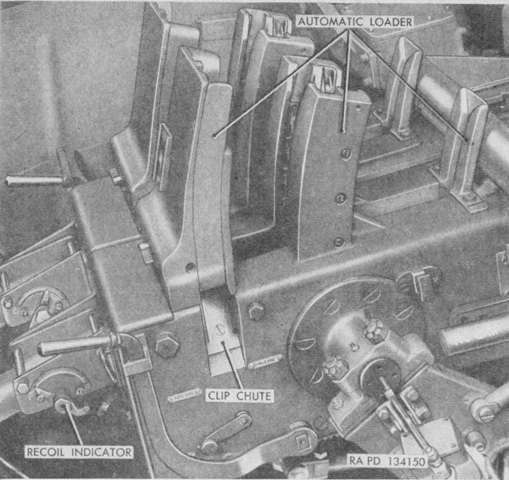
The automatic loaders are shown here. They were fed from above by 4-round clips. (Picture from TM 9-761A Self-propelled Twin 40-mm Gun T141.)
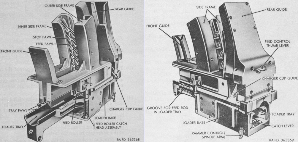
The left-side automatic loader is shown from the front and rear on the left and right, respectively. The loader fed cartridges individually into the loading tray, and the clips were removed during the process as well. As the cartridge was rammed into the chamber, it tripped the gun's extractors, which allowed the breechblock to raise. When the breechblock closed, the gun would fire automatically if the firing mechanism was depressed or the firing solenoid was actuated. (Picture from TM 9-7218 Twin 40-mm Full Tracked Self-propelled Gun M42 (T141).)
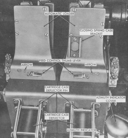
A feed control thumb lever was found on the rear of each automatic loader. When the lever was rotated to the arrow indicated, automatic fire would stop when one cartridge remained on the loader tray and one cartridge remained in the loader. This would allow the resumption of automatic fire by simply inserting a new clip into the loader. When not using this feature, the gun would fire until completely empty. (Picture from TM 9-7218 Twin 40-mm Full Tracked Self-propelled Gun M42 (T141).)
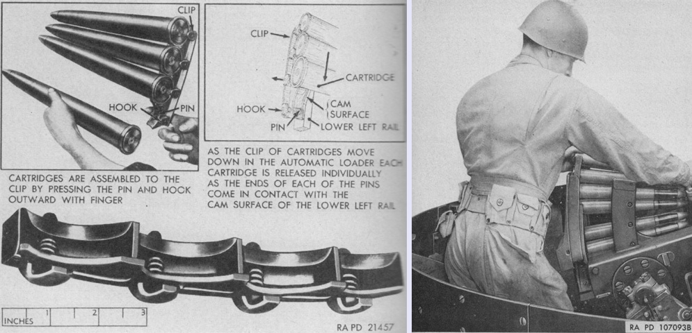
The charger clips were loaded by pressing the pin and hook outward, which allowed the cartridge to be inserted into the clip and secured once the hook was released. To load the gun, the hand operating lever was pulled back into its SAFE latch, and the clip was then pushed down into the guides of the automatic loader until the feed rollers were rotated and a round dropped onto the loading tray. (Picture from TM 9-761A Self-propelled Twin 40-mm Gun T141.)
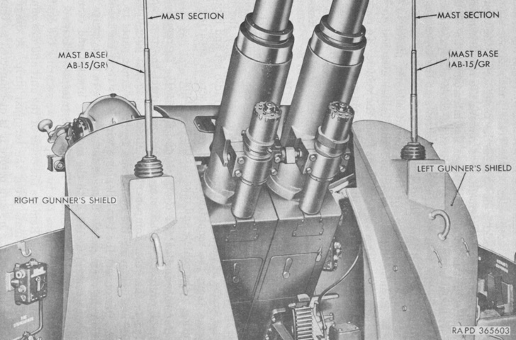
The radio antennas are shown mounted on the gun shields, and the recoil cylinders can be seen under the 40mm gun barrels. (Picture from TM 9-7218 Twin 40-mm Full Tracked Self-propelled Gun M42 (T141).)
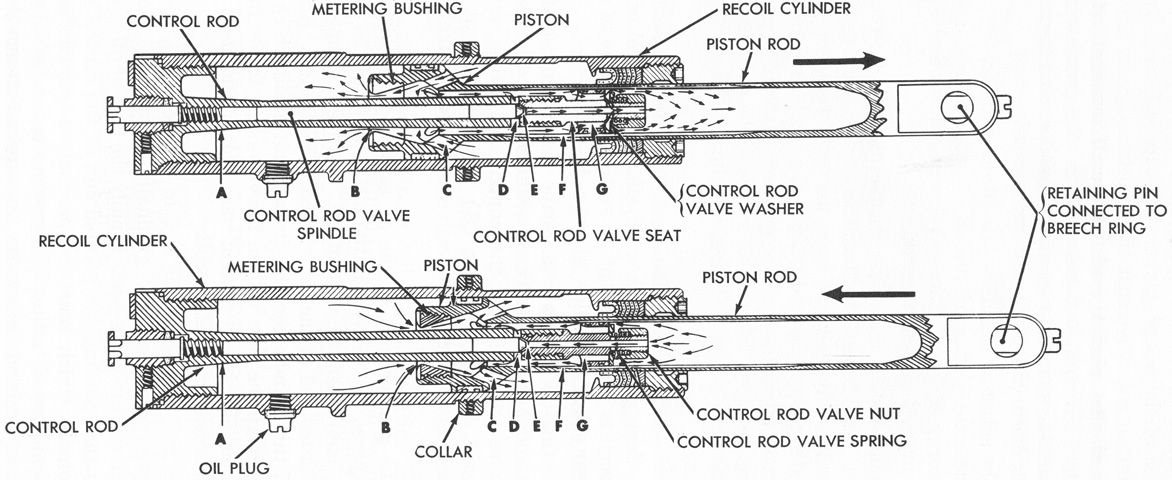
The recoil mechanism consisted of a recuperator spring held in tension around the breech end of the 40mm gun barrel, and a recoil cylinder under the tubular front end of the breech casing. A recoil cylinder is sketched above in recoil and counterrecoil at the top and bottom, respectively. The piston rod was connected to the breech ring, and upon firing the tube, piston rod, breech ring, and loader tray all moved to the rear by 7.4"-8.3" (19cm-21cm) during recoil.
As the piston rod traveled to the rear, oil in the rear of the recoil cylinder was forced through eight inclined openings (C) in the piston, through the metering bushing, and finally into the space in front of the metering bushing. The metering bushing traveled over the control rod, and as the bushing encountered the control rod's increasing rearward diameter, the resistance to the flow of oil was increased since the flow space (B) between the metering bushing and control rod decreased. This resistance, when combined with the recuperator spring, would arrest the rearward movement of the gun. Some oil would flow into the hollow space of the piston rod, through four holes (G) in the control rod valve seat, through tapered grooves (F) in the wall of the piston rod, through four radial holes (D) in the control rod, or through the bore of the control rod valve seat (E). During counterrecoil, the recuperator spring worked to push the gun back into battery, and this forward motion was tempered by the flow of oil back through the inclined openings in the piston and by the oil escaping the hollow piston rod through valves and grooves. The reverse taper at the front of the control rod (A) further reduced the flow space between the control rod and the metering bushing, and final buffing was via the dashpot action of the piston entering the seat in the forward end of the recoil cylinder. (Picture from TM 9-7218 Twin 40-mm Full Tracked Self-propelled Gun M42 (T141).)
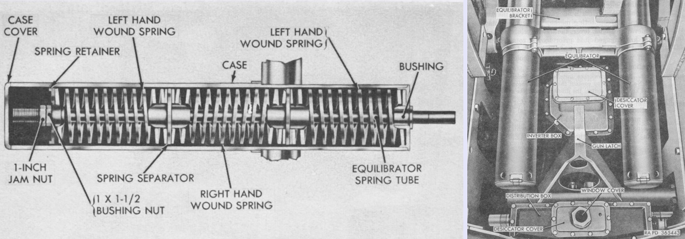
Two spring-type equilibrators were installed under the dual gun M2A1 between the top carriage frames in order to neutralize the unbalanced weight of the weapon and reduce the effort needed to elevate the guns. Operating as a unit, each equilibrator was a case holding three springs held in compression on an equilibrator spring tube. The equilibrator spring tubes were pivoted on equilibrator crossbars that projected from each side of the elevating sector. So, as the gun was depressed and the breech rose, the equilibrator springs were compressed and the muzzle-heavy tendency of the weapon was counteracted, obviating the need to brake the descent of the guns. As the guns were elevated, the energy stored in the springs was released and the springs helped pull the breeches down. (Picture from TM 9-7218 Twin 40-mm Full Tracked Self-propelled Gun M42 (T141).)
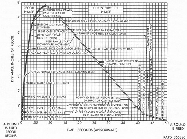
A complete firing cycle of the 40mm gun is shown in this graph. The combination of both guns could fire up to 240 rounds/minute, but after 120 rounds fired by both guns at the maximum rate a cooling break was needed. The estimated accuracy life of a barrel was 12,000 rounds. (Picture from TM 9-7218 Twin 40-mm Full Tracked Self-propelled Gun M42 (T141).)
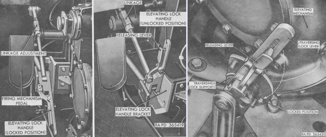
The elevating travel lock is shown locked and unlocked in the left and center images, respectively, and operation of the traversing lock lever beside the gunner's seat is illustrated at the right. The elevating lock secured the guns at 0°, while the traversing lock could secure the turret either straight ahead or straight back. (Picture from TM 9-7218 Twin 40-mm Full Tracked Self-propelled Gun M42 (T141).)
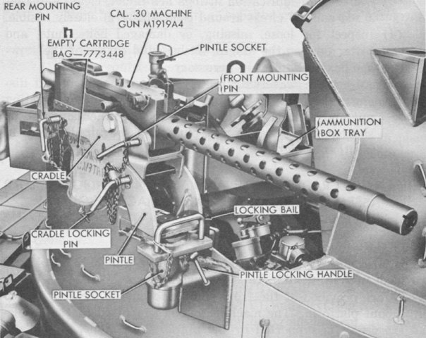
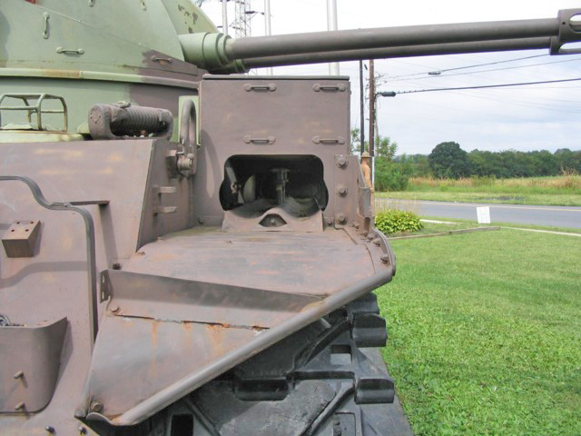
Pintles were found on the turret at the right side and the rear for mounting a .30cal machine gun M1919A4 in the assembly E10014, which was comprised of the machine gun cradle, pintle, and ammunition box. (Picture from TM 9-7218 Twin 40-mm Full Tracked Self-propelled Gun M42 (T141).)
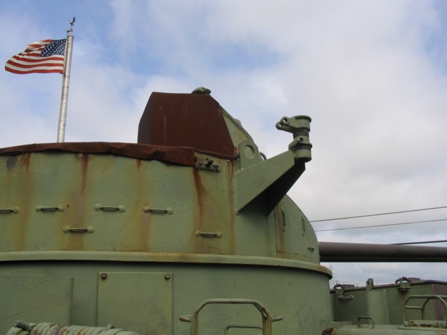
The side machine gun mount is seen here. The open-topped turret has been covered by now-rusty plate.
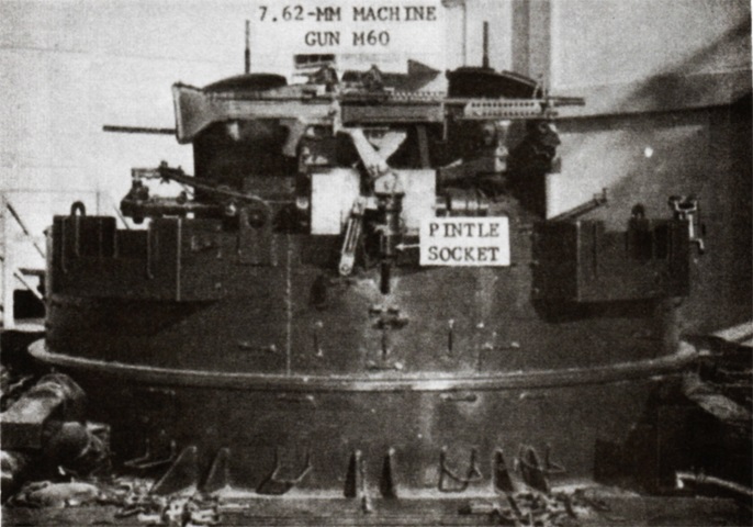
An M60 machine gun has been mounted on the rear pintle here, after the M1919A4 was retired. (Picture from FM 44-61 Procedures and Drills for Twin 40-mm Self-propelled Gun M42 and M42A1.)
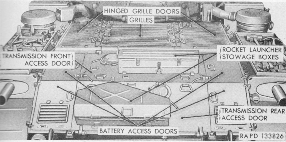
The engine compartment doors and grilles are labeled here. A 3.5" rocket launcher M20 could be stowed for self-defense. (Picture from TM 9-761A Self-propelled Twin 40-mm Gun T141.)
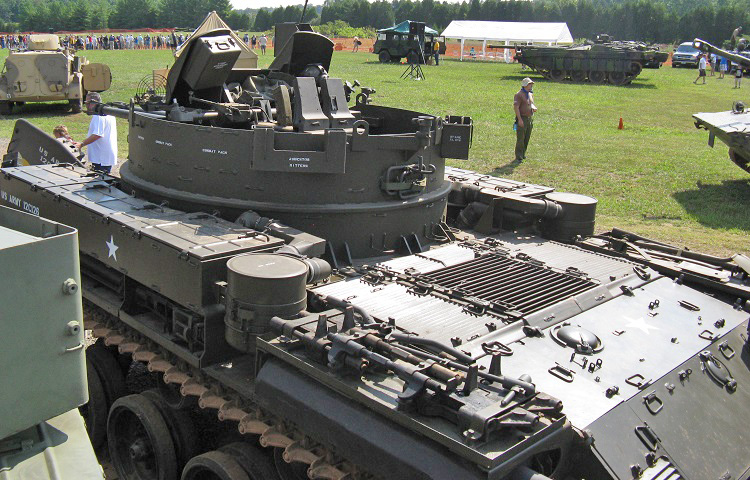
The rear deck is illustrated in this image. The air cleaners are behind the fender stowage boxes, and the engine compartment grille in the center of the rear deck is flanked to either side by two engine compartment grille doors. The plates in the center of the vehicle behind the engine grilles are the front and rear transmission access doors. These are flanked by the right and left battery access doors. The cover on the rear transmission access door is for the transmission oil filler, while the one on the front transmission access door is for engine oil. The gunner's speed ring sight for use with manual gun mount operation can be seen mounted to the turret to the gun shield's left.
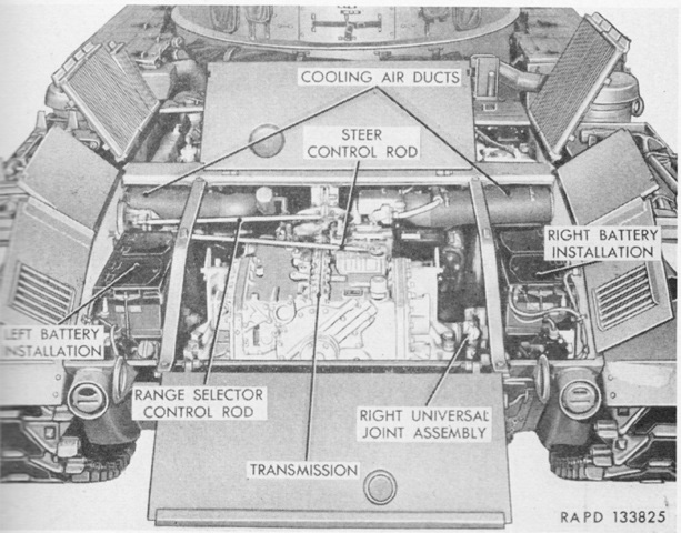
The engine compartment is open in this picture, revealing the installation of the transmission. (Picture from TM 9-761A Self-propelled Twin 40-mm Gun T141.)
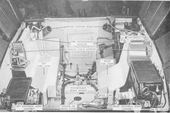
The power pack has been removed here. (Picture from TM 9-761A Self-propelled Twin 40-mm Gun T141.)
Late vehicles had an enlarged muffler for their auxiliary generator engines. (Picture from TM 9-7218 Twin 40-mm Full Tracked Self-propelled Gun M42 (T141).)
The turret is reversed on this vehicle. It is a late-production machine equipped with features like the auxiliary engine muffler on the tool rack above the right main engine muffler and reinforcing rings around the flash suppressors. The auxiliary engine muffler is one of the second type fitted; earlier mufflers were smaller and did not extend the entire length of the tool rack. (Picture courtesy Kristopher Barrington.)
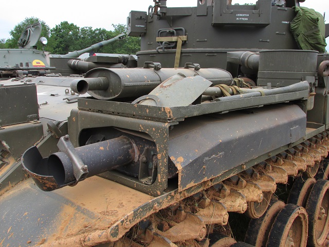
A closer shot of the mounting of the late auxiliary engine muffler and tool rack is provided here.
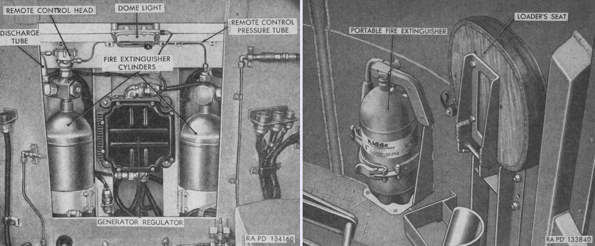
The fixed fire extinguisher system used two 10lb (4.5kg) CO2 cylinders mounted at the rear of the empty 40mm cartridge case disposal chute in the stowage compartment, shown here through the open engine compartment bulkhead. These were piped to discharge nozzles that were pointed down in the engine compartment over each fuel tank. Remote control handles were present on the bulkhead behind and to the left of the driver as well as on the hull roof behind the driver's hatch. In addition, a single 5lb (2.3kg) CO2 portable fire extinguisher was stowed along the wall of the gun mount, as seen on the right. (Pictures from TM 9-761A Self-propelled Twin 40-mm Gun T141.)
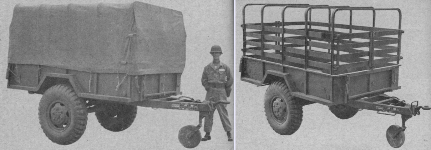
Each vehicle was provided with a 1½-ton cargo trailer M104 used to haul ammunition or other supplies. The canvas cover was to always be used when being towed due to the large amount of dust and mud the vehicle's tracks would raise. The trailer had a mechanical parking brake for use when unhitched. The trailer was 13'9½" (420.4cm) long overall, 8'3⅛" (251.78cm) tall empty, and 6'11" (210cm) wide, with a tread of 5'9⅝" (176.85cm). The trailer weighed 2,400lb (1,090kg) and could haul 5,500lb (2,500kg) on hard roads or 3,300lb (1,500kg) cross country. (Picture from FM 44-61 Self-propelled Twin 40-mm Gun T141.)
