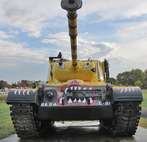
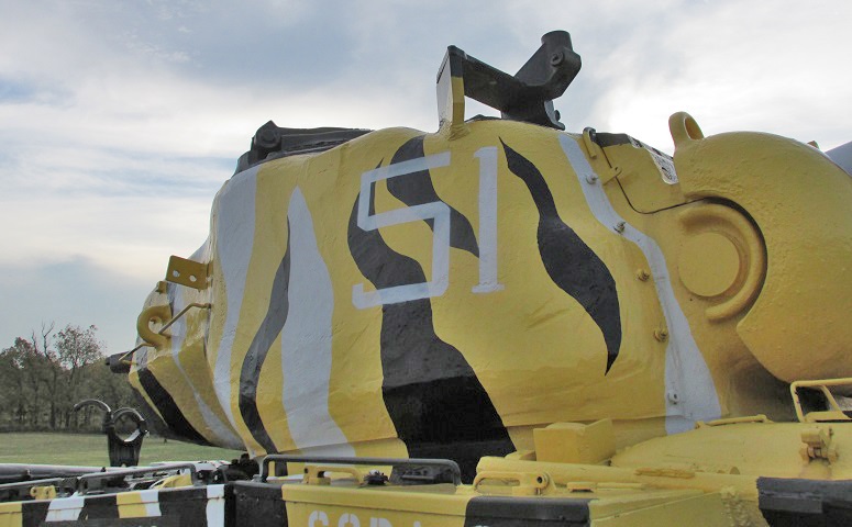
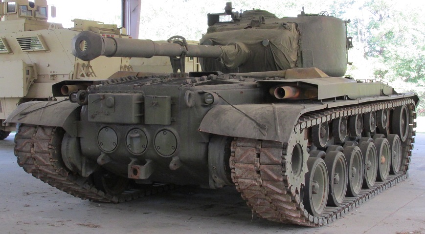
Medium Tank M46 Patton at the US Army Heritage and Education Center at Carlisle Barracks.
From this angle, the M46 Patton is very similar to the M26A1 Pershing. Each was armed with the M3A1 90mm gun, which features a bore evacuator and single-baffle muzzle brake.
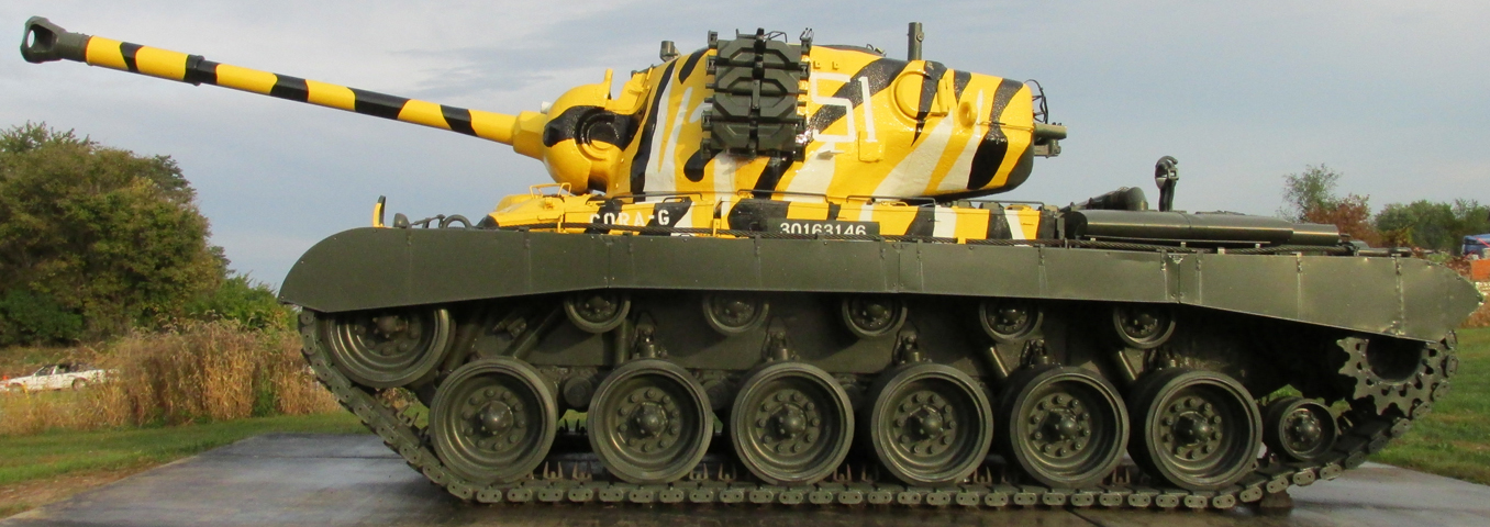
This view provides positive identification. Engine exhaust mufflers are mounted on the rear fenders, and a small track tension idler is between the rear road wheel and the drive sprocket. The gun travel lock on the rear deck is raised, and the pistol port in the side of the turret can be seen. Two sockets for mounting a .50cal machine gun are visible on the turret roof, one to the front and a taller one to the rear.
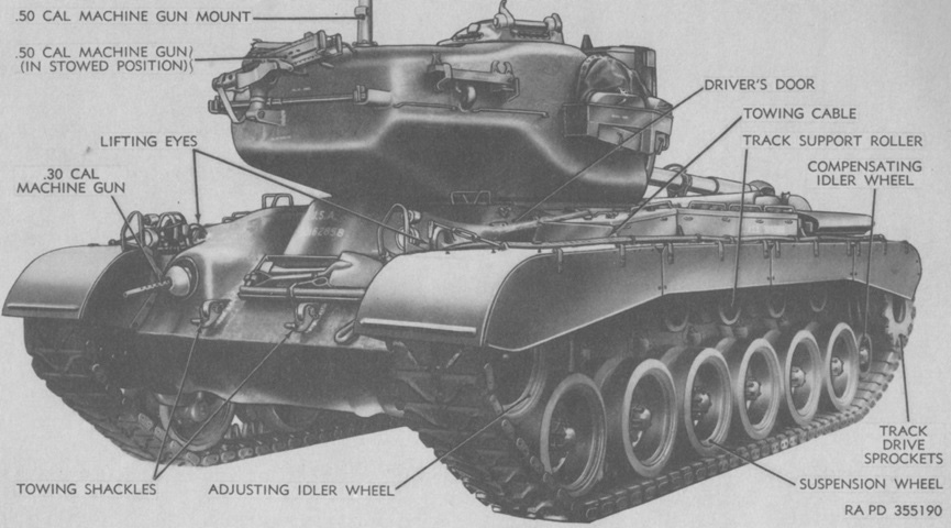
The .50cal machine gun is stowed on the turret rear, and the main gun is secured in its travel lock. (Picture from TM 9-718 Medium Tank M46 (T40).)
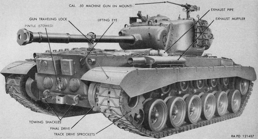
The 90mm gun is secured in its travel lock, and spare tracks are stowed on the turret side. (Picture from TM 9-718 Medium Tanks M46 and M46A1.)
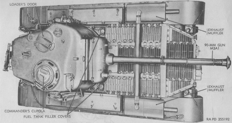
Features of the rear hull are seen here. (Picture from TM 9-718 Medium Tanks M46 and M46A1.)
The new air-cooled engine required more airflow, and consequently the engine deck featured more grilles than the outgoing M26. (Picture from TM 9-718 Medium Tank M46 (T40).)
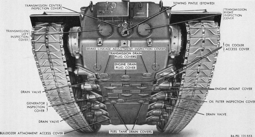
Openings in the hull rear and bottom are labeled in this image. (Picture from TM 9-718 Medium Tanks M46 and M46A1.)
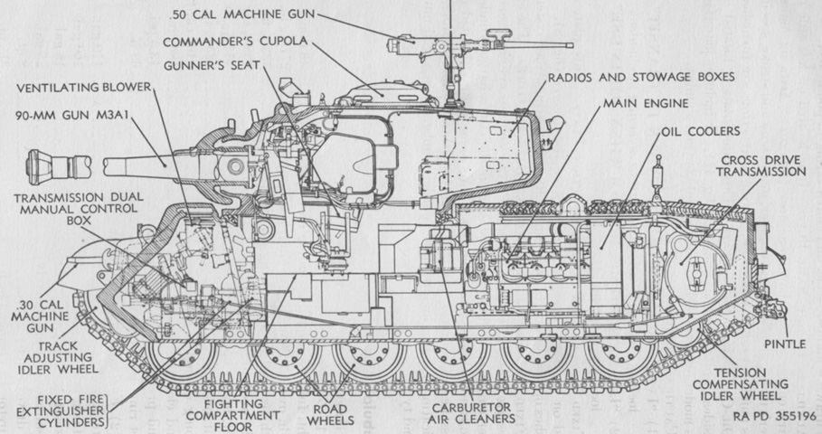
The interior layout and armor distribution can be seen in this cross-section. (Picture from TM 9-718 Medium Tank M46 (T40).)
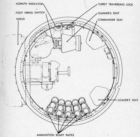
This plan view of the turret interior reveals the spatial relationship between the crew, controls, and ready ammunition. (Picture from TM 9-718 Medium Tanks M46 and M46A1.)
The TC was now provided with a mount 6580030 for the .50cal MG in front of his position. This was ergonomically better than the setup found on the M26, with solely a mount behind the commander.
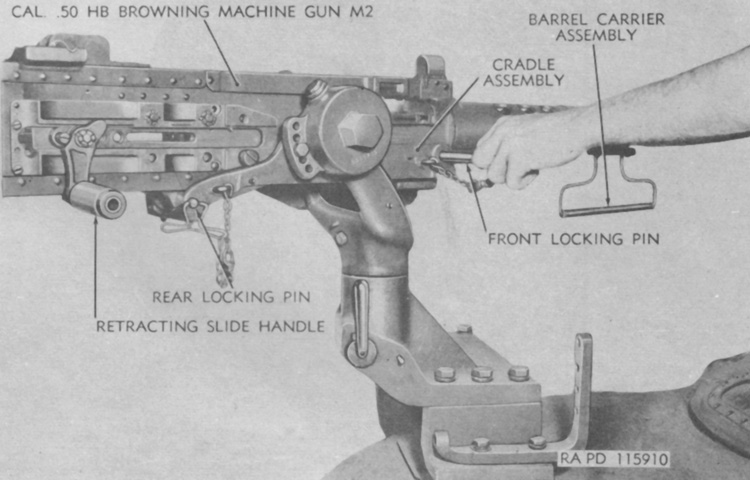
The .50cal machine gun is mounted in the cradle pintle assembly 6580030 on top of the gunner's periscope guard. The gun is pointed to the rear of the tank in the image, but with the commander's cupola visible in the lower right, it is obvious how much handier a location this was compared to earlier tanks. (Picture from Weapon Mounts for Secondary Armament.)
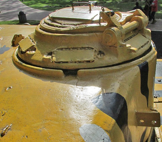
A view of the commander's cupola from behind is shown here, with the vision blocks and periscope opening blanked over. The contour of how the turret side meets the cupola can be seen.
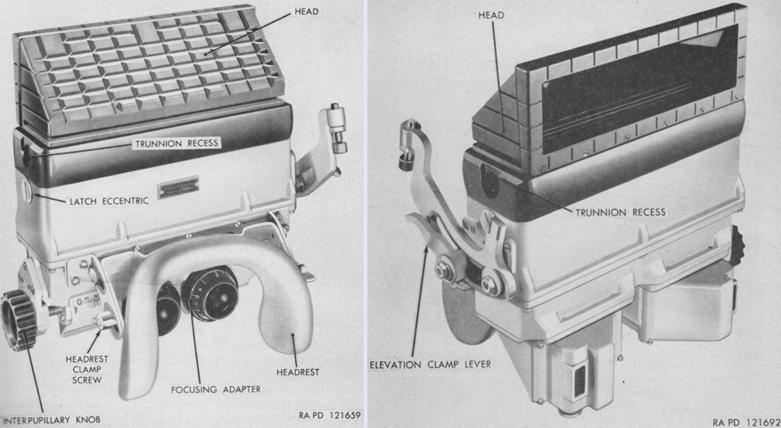
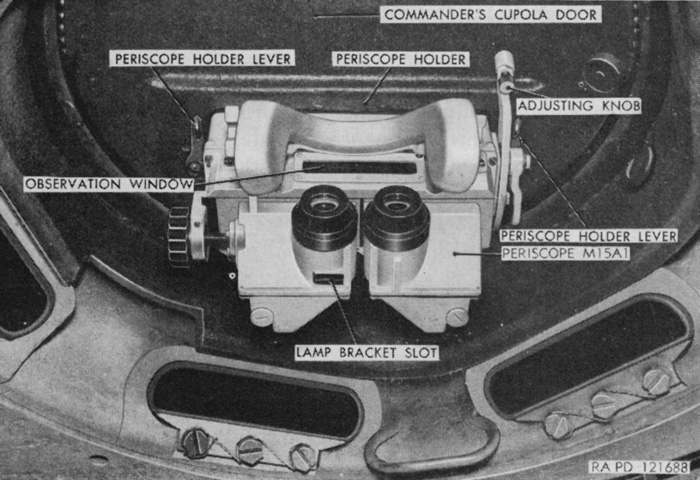
The periscope M15 or M15A1 could be installed in the commander's cupola door. The M15A1 is seen above, and had a slightly smaller vertical field of view when using the unity window compared to the M15, at 10°20' compared to 13°30'. Their optical characteristics were otherwise similar. The body of the M15A1 had no provision for mounting the instrument light M33. The periscope weighed 16lb 12oz (7.598kg). (Picture from TM 9-718 Medium Tanks M46 and M46A1.)
The periscope M15A1 is shown mounted. To move the M15 vertically for elevation, it was unlocked by pushing the elevation clamp lever forward and then rotating the elevating knob until the desired elevation was reached. After the M15A1 was unlocked by pushing the elevation clamp lever forward, it was instead moved through its vertical arc by hand. (Picture from TM 9-718 Medium Tanks M46 and M46A1.)
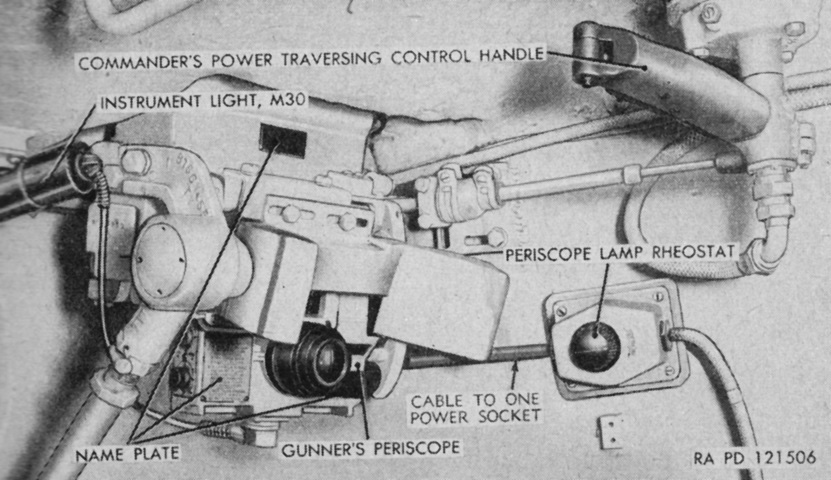
The commander could use his own traversing control handle to traverse the turret and override the gunner's inputs. Squeezing the lever on the front of the handle disengaged the gunner's control handle, and turning the handle clockwise traversed the turret to the right, and counterclockwise traversed the turret to the left. Pushing the handle farther in either direction increased the speed of traverse. (Picture from TM 9-718 Medium Tanks M46 and M46A1.)
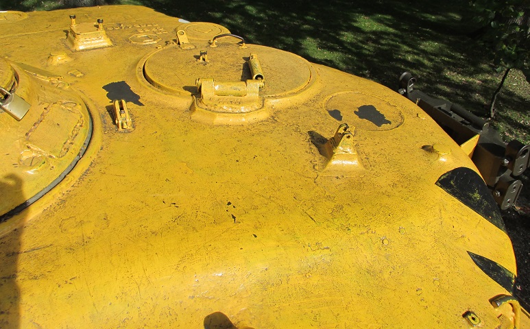
The loader's hatch opened forward, and the catch can be seen on the roof. The circular indentation to the loader's front left shows where his rotating periscope would have been, and the square base for the .50cal machine gun mount is on the rear roof between the loader and commander. Two antenna base mounts are also present, one directly behind the loader's hatch and one at the extreme rear of the turret, on the left-hand border of the frame.
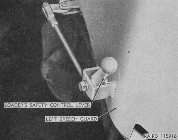
The loader's safety control lever was found on the left side of the breech guard, and it helped prevent accidental firing of the main gun when the loader was not clear of the recoil path. It was connected to the firing linkage, and when the lever was pulled to the rear the firing plunger was permitted to move in the firing linkage in order to fire the 90mm gun. When the lever was pushed forward, the firing plunger could not move and the gun would not fire. (Picture from TM 9-374 C1 90-mm Guns M3 and M3A1 for Combat Vehicles.)
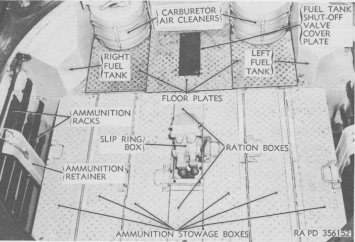
The floor plates on the ammunition stowage boxes are shown here closed. (Picture from TM 9-718 Medium Tank M46 (T40).)
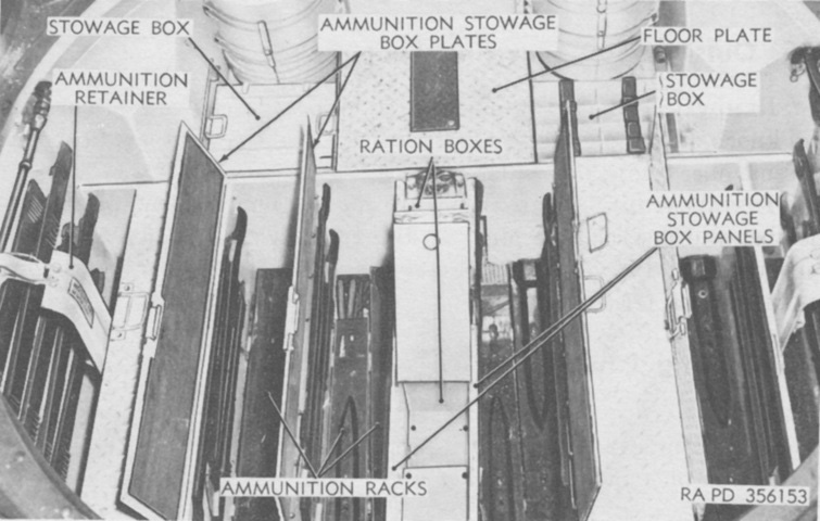
The floor plates have been opened for this image. (Picture from TM 9-718 Medium Tank M46 (T40).)
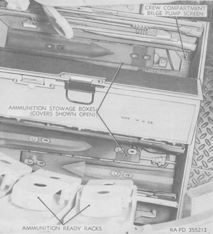
A closer view of the floor ammunition boxes is provided here. (Picture from TM 9-718 Medium Tank M46 (T40).)
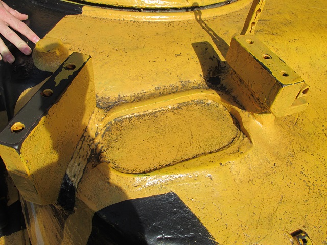
With the horizontal portion of the periscope guard/.50cal machine gun mount removed, the blanked-off aperture for the gunner's M10F periscope is easily seen. The commander's vane sight is mounted on the inboard vertical portion of the periscope guard.
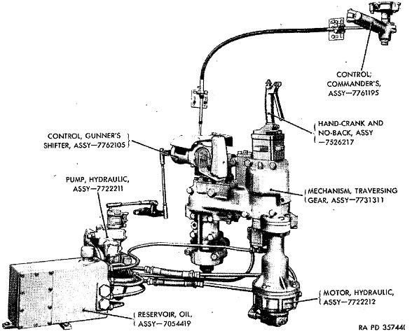
The turret hydraulic traverse mechanism is diagrammed in this image. The gunner and commander both had traverse controls, but the commander received precedence so he could override the gunner's inputs. The hand crank between the gunner and commander could be used to rotate the turret if the hydraulic system became inoperable. (Picture from TM 9-1718D Ordnance Maintenance--Hydraulic Turret Traversing Mechanism (Oilgear) for Medium Tank M46.)
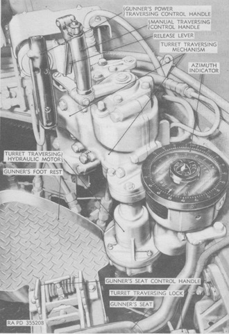
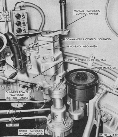
The gunner's controls are labeled here. Power traverse was accomplished by rotating the power traversing control handle clockwise or counterclockwise; greater rotation of the handle led to faster traverse. (Picture from TM 9-718 Medium Tank M46 (T40).)
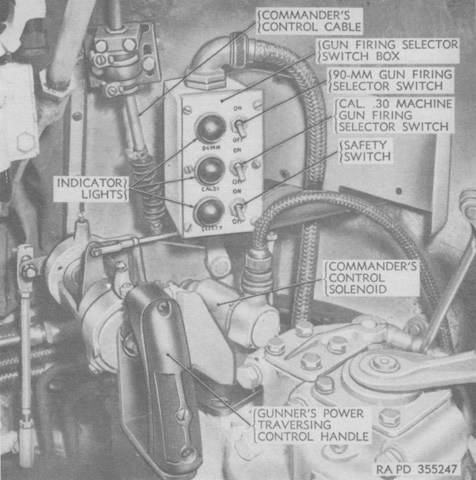
The selector switch box allowed the gunner to arm the 90mm or coaxial machine gun firing circuits. The safety switch controlled the circuit from the turret switch box firing switch to the selector switches and indicator lights, as well as to the gunner's hand and foot firing switches. (Picture from TM 9-718 Medium Tank M46 (T40).)
A later-production gunner's station can be contrasted with the earlier images above. (Picture from TM 9-718 Medium Tanks M46 and M46A1.)
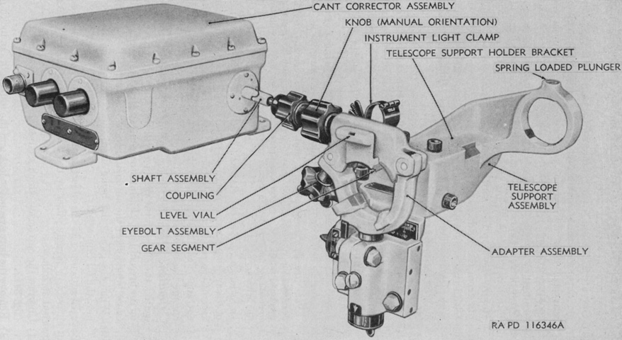
The telescope mount T173 used for the telescopes T152, M71E5C, or T151E1 contained an electronic cant corrector assembly that could account for cant angles up to 15° right or left of zero. The telescope's rear locating pin rear engaged with a slot in the gear segment, and after the telescope was leveled using the mount's manual orientation knob, rotation of the shaft from the cant corrector would orient the telescope so that cant was counteracted. (Picture from TM 9-718 Medium Tanks M46 and M46A1.)
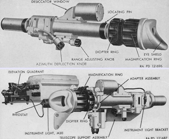
The telescope T152 is seen alone at the top and installed in the telescope mount T173 at the bottom. Both it and the T151 were continuously variable from 4x to 8x magnification, with fields of view from 15° to 7½°. (Picture from TM 9-718 C1 Medium Tanks M46 and M46A1 and TM 9-718 Medium Tanks M46 and M46A1.)
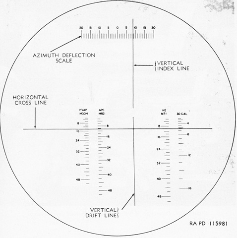
Left to right, the reticle for the telescopes T152 and T151E1 contained graduations for 90mm ammunition hypervelocity armor-piercing M304, armor-piercing capped M82, and high-explosive M71, as well as the coaxial machine gun. The graduations on the 90mm ammunition scales represented 200 yards (180m), while the coaxial machine gun's graduations represented 100 yards (90m). To use the telescopes, the range adjusting knob was turned until the horizontal cross line indicated the desired range on the appropriate ammunition range scale. The azimuth deflection knob was turned until the vertical index line indicated the desired deflection on the azimuth deflection scale, which was graduated in 1-mil increments up to 20 mils either side of zero. The turret was then traversed and the gun elevated until the intersection of the reticle lines was over the target. (Picture from TM 9-718 Medium Tanks M46 and M46A1.)
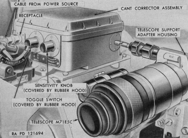
The telescope M71E5C is shown installed in the telescope mount T173. The M71E5C was a telescope M71C that had had its reticle rotated 180° so that it would be in the correct orientation when the telescope's locating pin engaged the slot in upper portion of the adapter assembly of the T173 mount. The locating slot in the previous telescope mounts M72 and T131 was instead at the 6:00 position. (Picture from TM 9-718 Medium Tanks M46 and M46A1.)
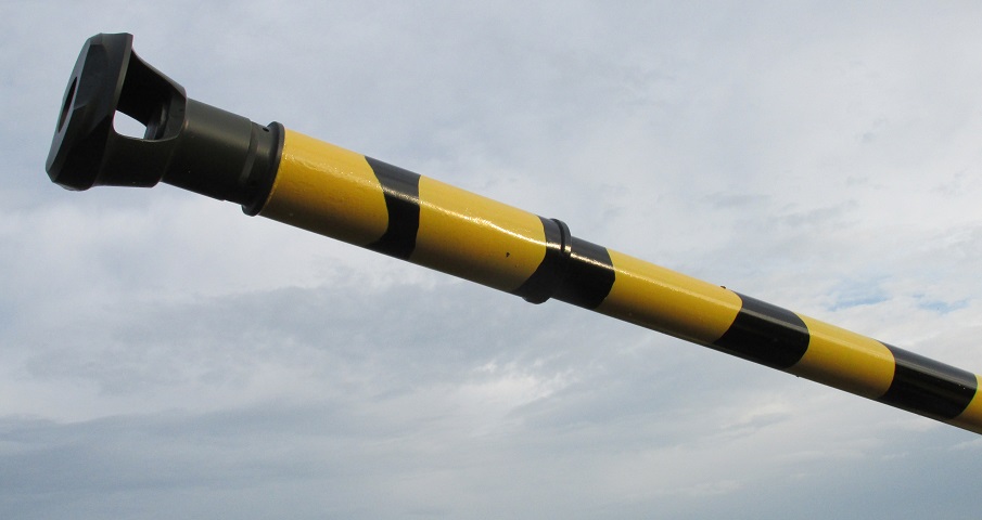
A closeup of the single-baffle muzzle brake and the bore evacuator on the front of the gun tube is provided here. The gun weighed 2,260lb (1,030kg) without the muzzle brake and bore evacuator, and the tube could survive an estimated 1,600 equivalent full-charge rounds.
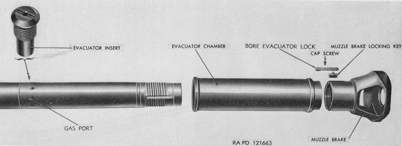
The muzzle brake and bore evacuator chamber are shown removed from the gun tube. (Picture from TM 9-718 Medium Tanks M46 and M46A1.)
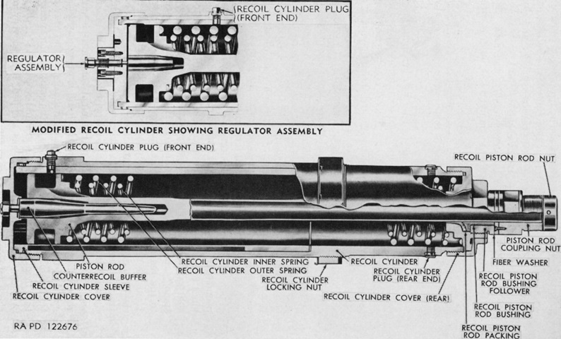
A cross-section of one of the two hydrospring recoil cylinder assemblies is drawn here. Early tanks used counterrecoil buffers without regulator assemblies, but late M46s and all M46A1s had these fitted. The regulator was to be opened during cold temperatures as the viscosity of the hydraulic oil increased. When the gun was fired, the gun pulled the attached piston rods to the rear, against the resistance of the recoil cylinder springs and oil flowing through tapered cut-outs in the cylinder sleeves around the piston rods. After the rearward motion was arrested, the compressed springs returned the gun to battery. (Picture from TM 9-718 Medium Tanks M46 and M46A1.)
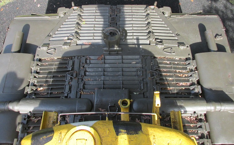
Looking down onto the rear deck, the increased airflow necessitated by the new air-cooled engine becomes apparent when compared with the rear deck of the M26.
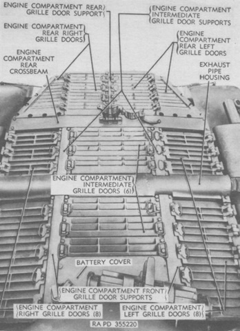
The various components of the engine deck are labeled here. (Picture from TM 9-718 Medium Tank M46 (T40).)
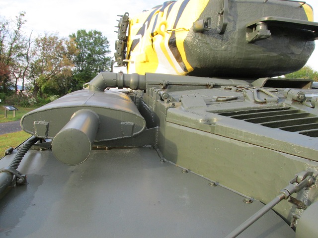
The mounting of the engine muffler on the rear fender can be seen in this image, as well as the mounting bolts and bracket for the fender itself. The grille to the right of the image provided access to the transmission, and stowage mounts for the .50cal MG can be seen on the turret rear. A towing cable is routed below the muffler.
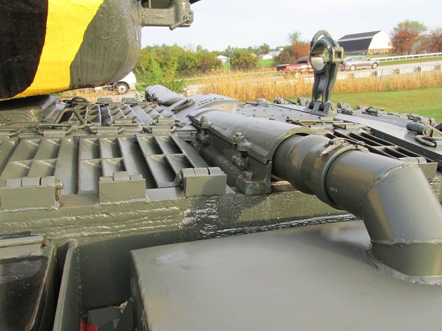
Details of the exhaust pipe connection to the muffler can be seen here. Under the turret bustle in the center of the rear deck is the center battery cover.
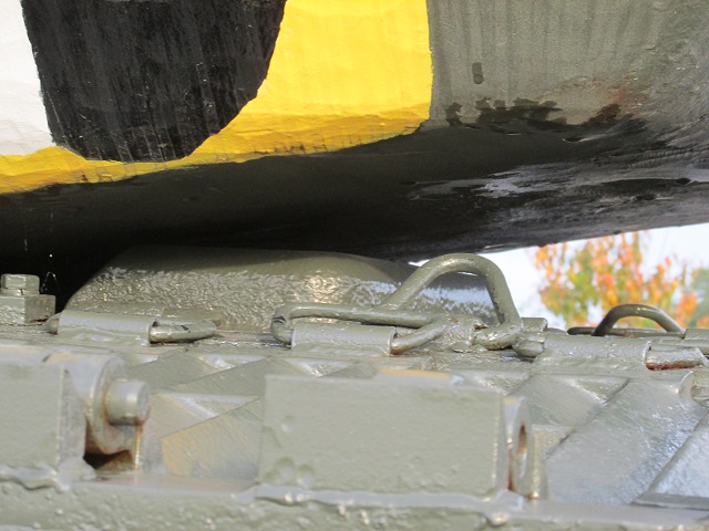
A closer image of the battery cover and the underside of the turret bustle is provided here.
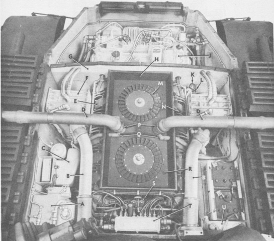
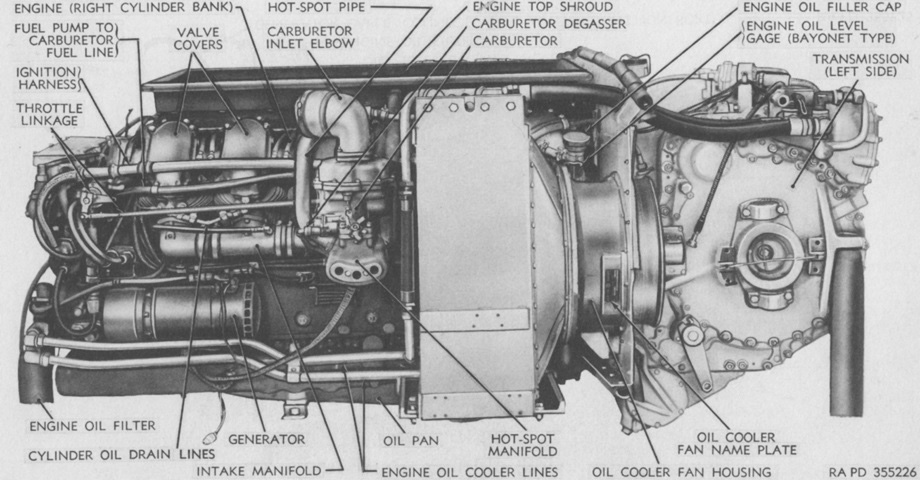
The hinged grilles have been opened and the remaining deck grilles removed here. A. Right fuel tank. B. Air cleaner pipes. C. Auxiliary generator and engine. D. Exhaust pipes. E. Left cylinder bank. F. Oil cooler. G. Engine rear shroud. H. Engine top shroud. J. Transmission. K. Engine oil filler cap. L. Engine oil level gage (bayonet type). M. Engine fan. N. Right cylinder bank. P. Clamps. Q. Hot-spot pipes. R. Engine top shroud section. S. Lifting eye. T. Engine junction box. U. Left fuel tank. (Picture from TM 9-718 Medium Tank M46 (T40).)
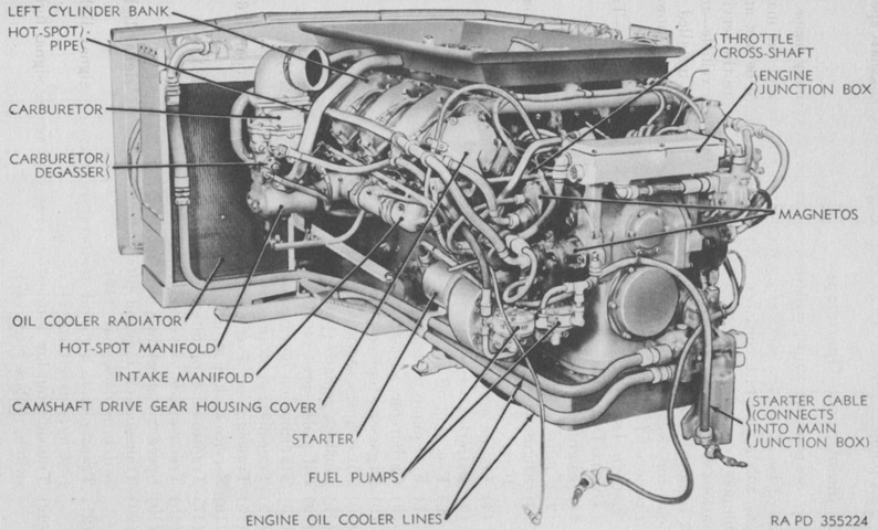
The new engine is seen here from the left front. It used overhead valves with a single camshaft for each bank of six cylinders, the valves being actuated via rockers in each cylinder head. (Picture from TM 9-718 Medium Tank M46 (T40).)
Bore and stroke were both 5.75" (14.6cm), yielding a displacement of 1,791.75in³ (29,361.4cm³). Compression ratio was 6.5:1, and maximum governed speed under full load was 2,800rpm. (Picture from TM 9-718 Medium Tank M46 (T40).)
The cross drive transmission is mounted to the engine in this image. (Picture from TM 9-718 Medium Tank M46 (T40).)
The left rear of the transmission and oil coolers is shown here. Dry, the transmission weighed about 3,000lb (1,400kg) was about 30" (76cm) long, 40.375" (102.55cm) high, and 48" (120cm) wide over the flanges. It combined the transmission, steering, and braking functions into a single assembly. (Picture from TM 9-718 Medium Tank M46 (T40).)
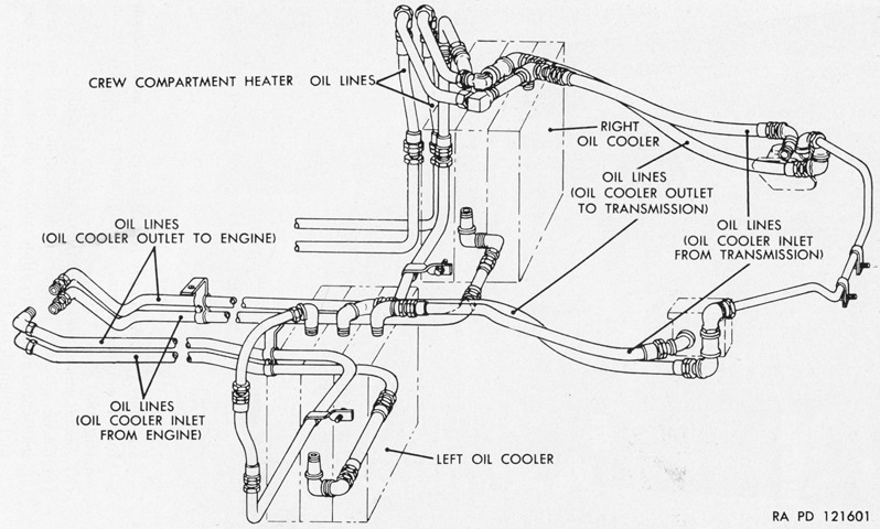
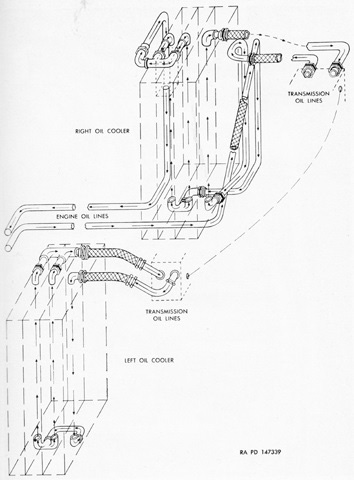
The oil cooler lines are diagrammed here. The oil cooler on each side used one core for engine oil cooling and two cores for transmission oil cooling. Two lines emanating from the right oil cooler were connected to the heater in the crew compartment. (Picture from TM 9-718 Medium Tanks M46 and M46A1.)
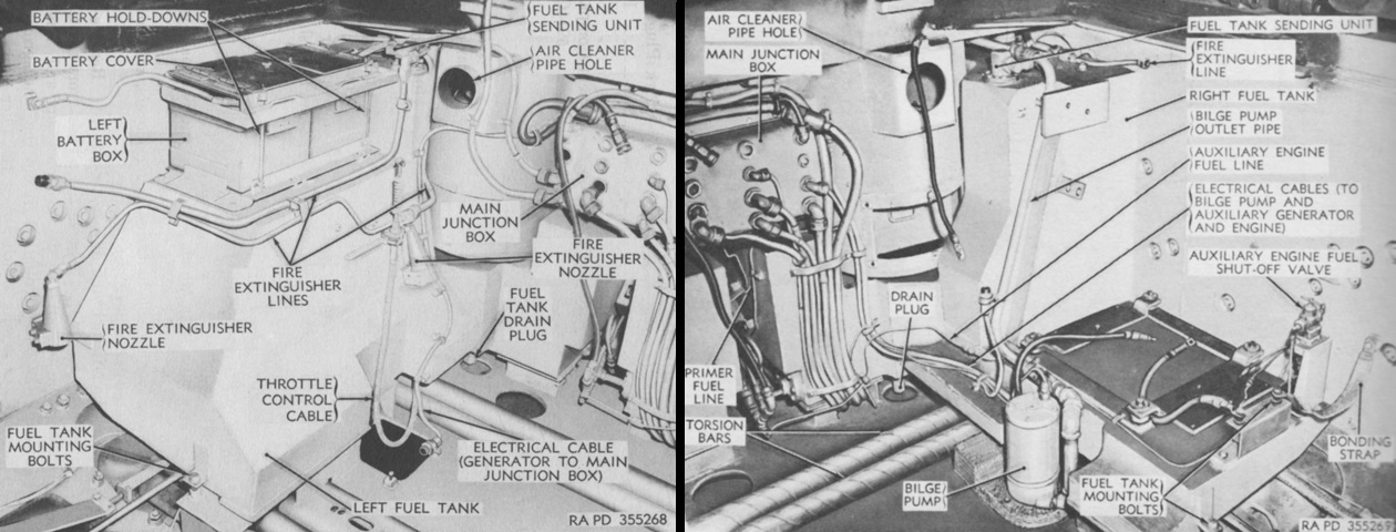
The left and right fuel tanks are shown on the left and right, respectively. In addition to two 12-volt batteries contained in the forward part of the engine compartment, two more 12-volt batteries were mounted on the left fuel tank as seen here. The mount for the auxiliary engine and generator is on the right fuel tank. (Picture from TM 9-718 Medium Tank M46 (T40).)
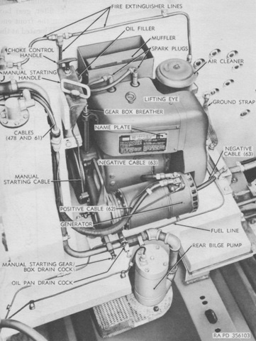
The auxiliary generator engine was a Wisconsin TFT constant-speed (2,800rpm), air-cooled, 2-cylinder, 4-cycle gasoline engine. Bore and stroke were both 3.25" (8.26cm), yielding 13.6 horsepower. Fuel was provided via the main engine fuel tanks. The generator was the same type as found on the main engine, a 150-ampere, 24-volt, compound-wound, four-brush, field-regulated type. (Picture from TM 9-718 Medium Tank M46 (T40).)
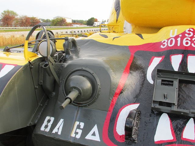
The bow machine gun mount is shown here, and the pioneer tool stowage rack is mounted on the tank's upper hull front. The siren is visible just behind the headlight.
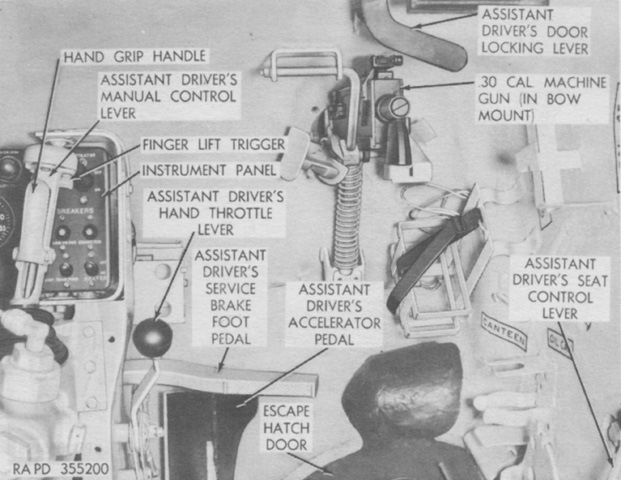
The assistant driver's position is shown here. He had duplicated driving controls, and could take over from his position if the driver tired or was injured. Similar to earlier tanks, the bow machine gun was aimed simply by observing tracers and impacts. The machine gun's traveling lock rod is engaged in this image. (Picture from TM 9-718 Medium Tank M46 (T40).)
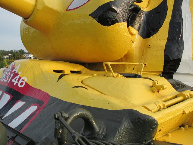
The apertures for the ventilator mounted between the drivers can be seen in this picture. Details of the driver's periscope housing guard, door hinge, and door hold open catch are shown, as well as the attachment of the fender mounting bracket to the hull lifting eye.
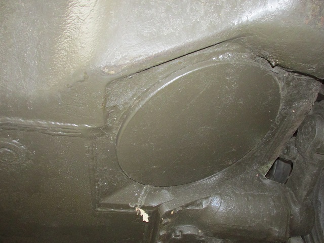
Each driver was provided with an escape hatch in the floor. The driver's hatch location is shown here, and the assistant driver's would occupy the spot on the opposite side of the hull .
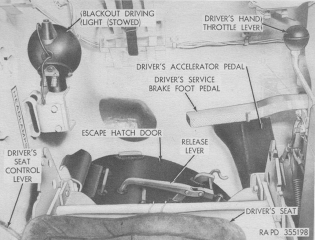
The floor of the driver's position is shown here. The paint of the escape hatch door contrasts with the white of the interior. The accelerator pedals for the two drivers were connected by a cross-shaft, so that they both moved when one was pressed. (Picture from TM 9-718 Medium Tank M46 (T40).)
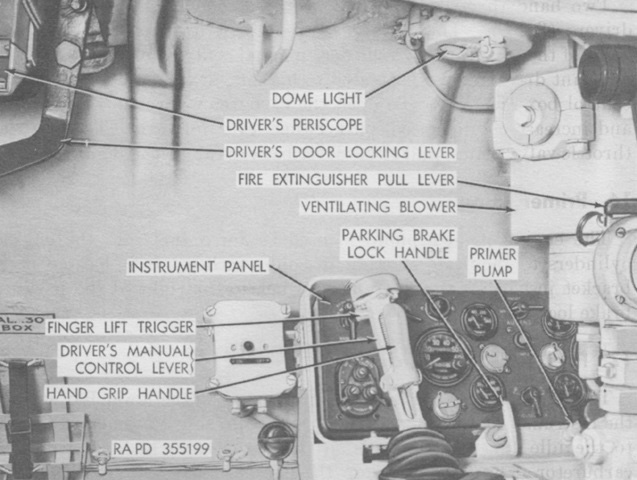
The front of the driver's position is labeled in this picture. The parking brake locking handle arrested movement of the parked vehicle by locking the service brakes into position as the service brake pedal was depressed. The manual control lever controlled both steering and the transmission speeds. The shift positions were controlled by pushing the lever into one of four longitudinal positions: from front to rear, they were neutral, low, high, and reverse. Shifting into or out of neutral required squeezing the hand grip handle. To shift into reverse from low or high (or vice-versa), the finger lift trigger or the hand grip handle were required to be actuated. Shifting into or out of reverse necessitated that the tank be completely stopped. Steering was accomplished by moving the manual control lever to the right or left, and it was spring-loaded to return to center upon release. While reversing, the vehicle rear would turn in the opposite direction that the handle was pressed. Steering with the lever while the transmission was in neutral would cause the tracks to run in opposite directions. (Picture from TM 9-718 Medium Tank M46 (T40).)
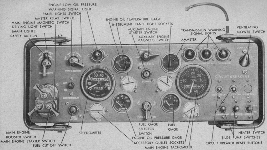
The driver's instrument panel is detailed. (Picture from TM 9-718 Medium Tanks M46 and M46A1.)
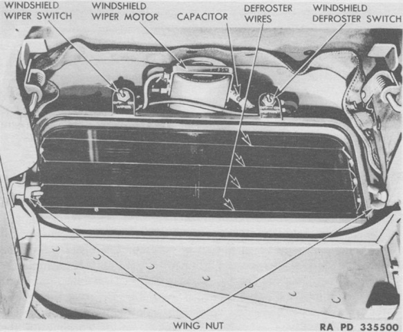
Both drivers were provided with a hood to emplace over their open hatches during inclement weather. The hood had an electrical windshield wiper and an electrical defroster, each of which had toggle switches on the top of the windshield. (Picture from TM 9-718 Medium Tank M46 (T40).)
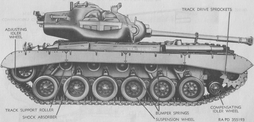
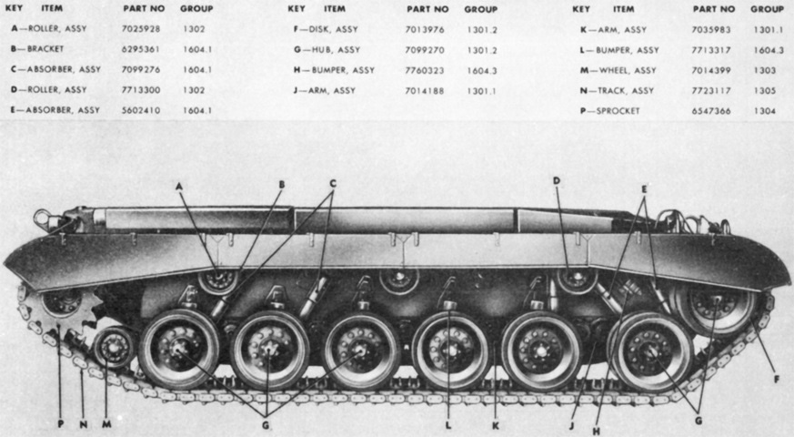
Nomenclature for the suspension components is given here. (Picture from TM 9-718 Medium Tank M46 (T40).)
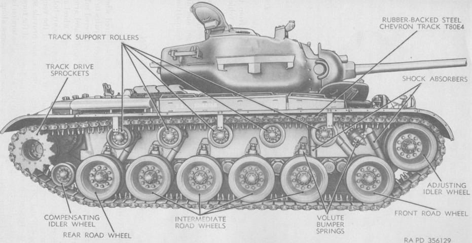
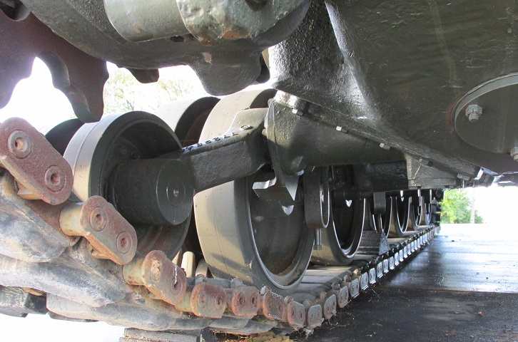
The sandshields have been removed, revealing more details of the suspension. (Picture from TM 9-718 Medium Tank M46 (T40).)
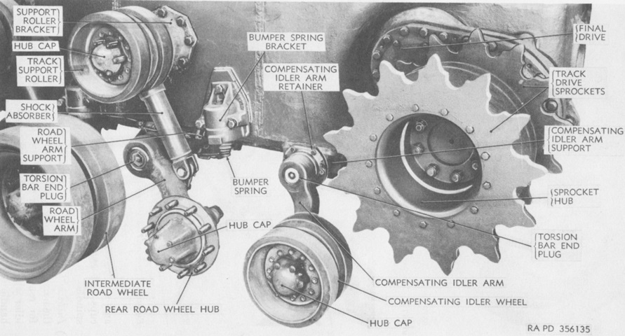
The rear road wheel hub, compensating idler wheel, and drive sprocket are detailed in this image. (Picture from TM 9-718 Medium Tank M46 (T40).)
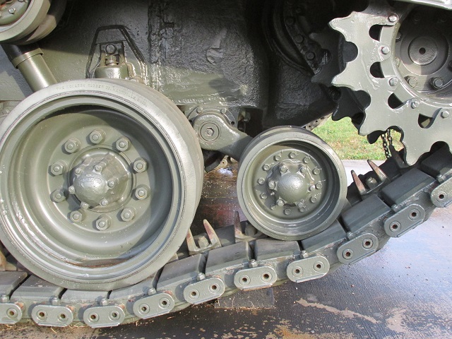
The small idler wheel in front of the drive sprocket was intended to help maintain track tension and prevent the tracks from being thrown. A shock absorber and bump stop are visible behind the rear road wheel.
The swing arm of the small idler wheel is shown here.
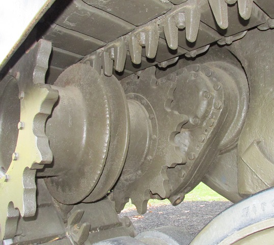
Compared to the downward-pointing final drives on the M26, those on the M46 pointed more to the rear, consequently raising the drive sprocket compared to the earlier tank.
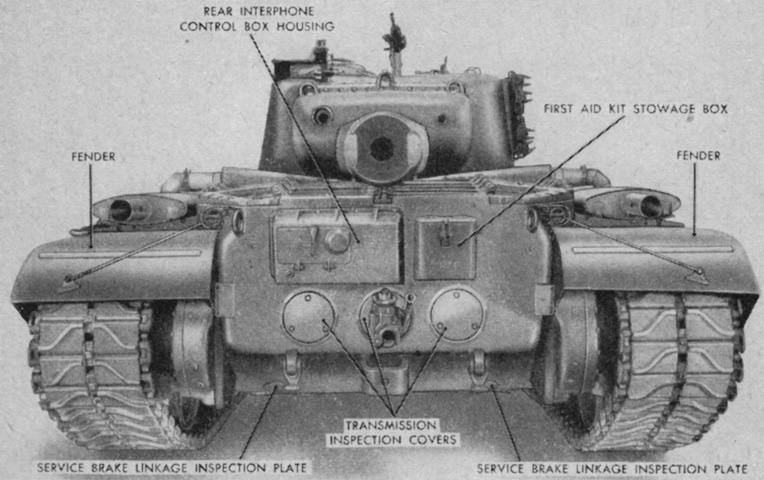
The hull rear plate provides further differentiation from the M26. The round covers in the rear plate are transmission access plates, and the box above these housed an interphone system. The turret on this vehicle is reversed, and the gun is resting in its travel lock.
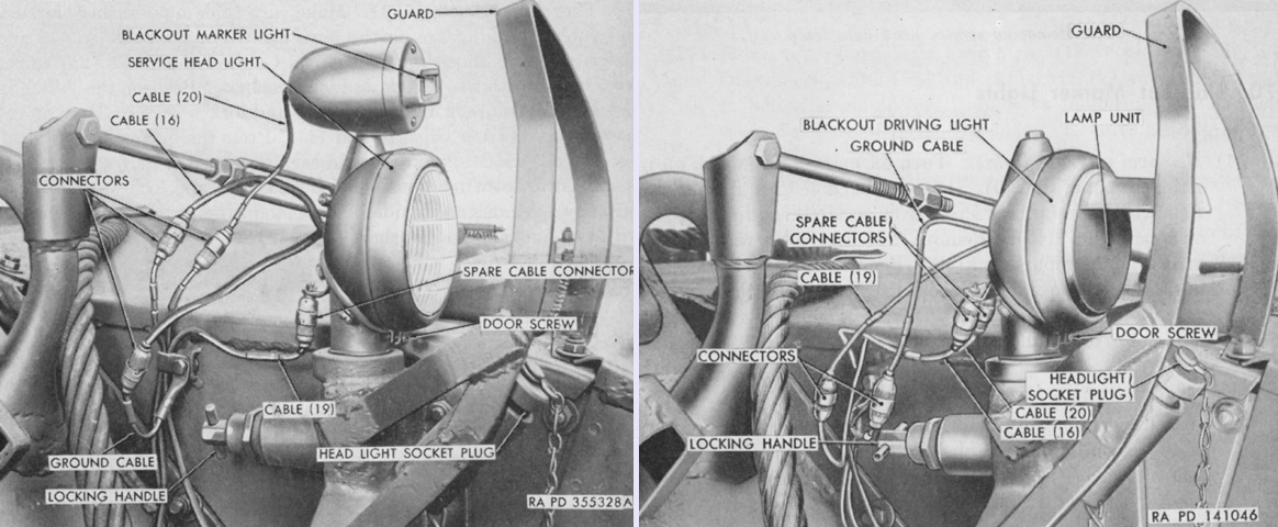
The headlights were mounted on the inner sides of the front fenders. The service headlights were combination-type units that incorporated blackout marker lights as well. These could be removed or exchanged for blackout driving lights as shown on the right. (Picture from TM 9-718 Medium Tanks M46 and M46A1.)
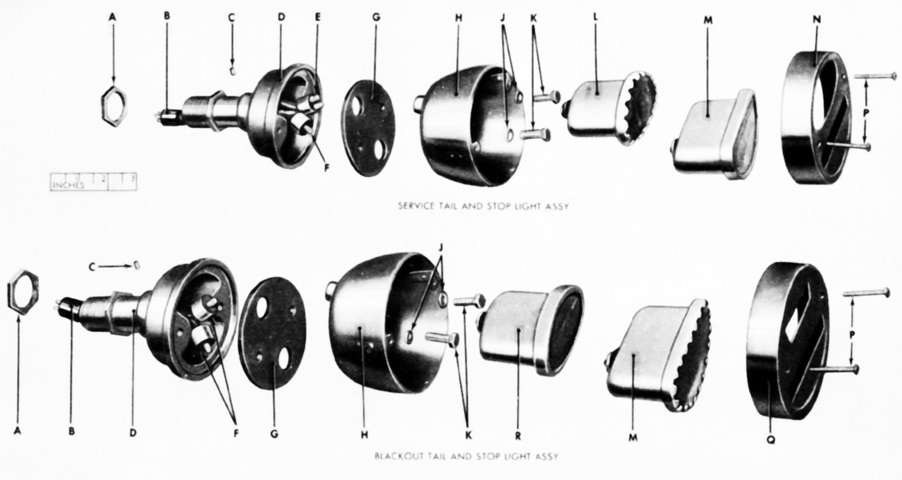
Exploded views of the service tail and stop light assembly and blackout tail and stop light assembly are provided here. (Picture from ORD 9 SNL G-244 List of All Service Parts of Tank, Medium, M46 and M46A1.)
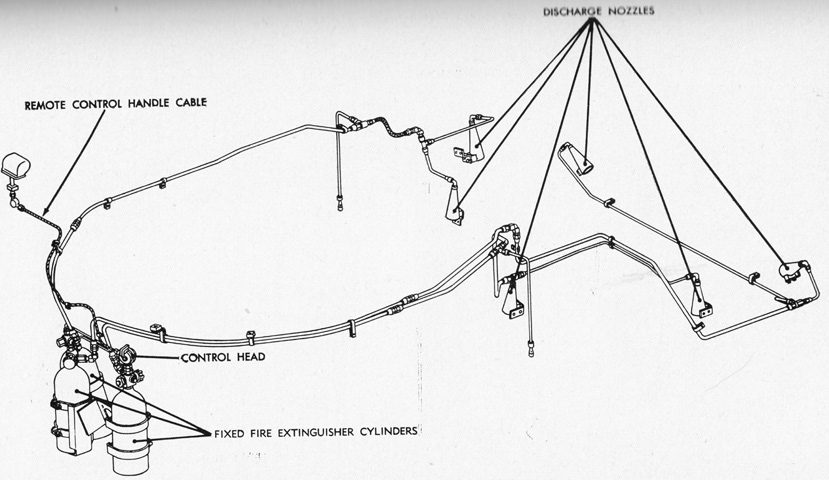
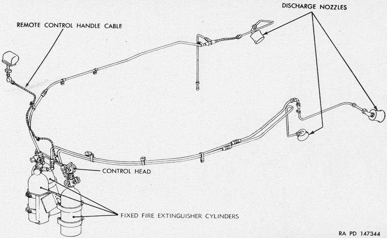
Three 10lb (4.5kg) carbon dioxide fire extinguisher cylinders were mounted behind the drivers and used to smother fires in the engine compartment. Six discharge nozzles were used with the fixed cylinders; in addition, two 4lb (1.8kg) portable fire extinguishers were carried, one to the left of the fixed cylinders and one in the turret bulge. (Picture from TM 9-718 Medium Tanks M46 and M46A1.)
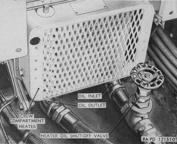
The crew compartment heater was mounted on the floor ahead of and between the drivers, and it used the circulation of hot transmission oil to provide heat. (Picture from TM 9-718 Medium Tanks M46 and M46A1.)
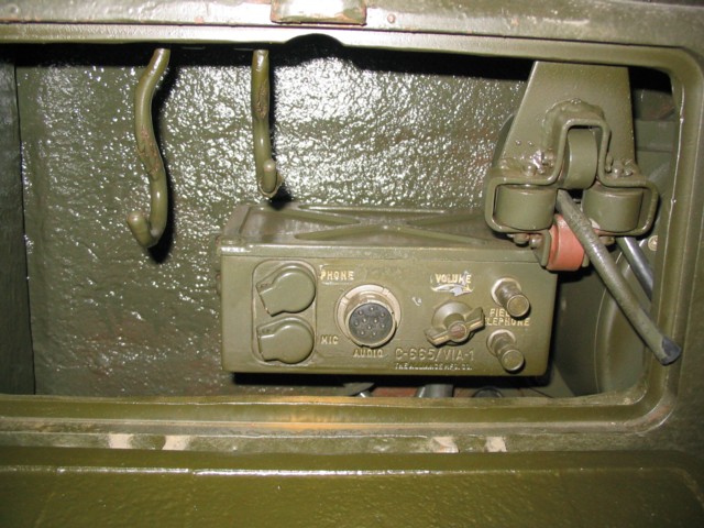
A look inside the external interphone box reveals the handset is missing from this vehicle, but the control box and take-up reel remain. Two vertical hooks are in the left of the box.
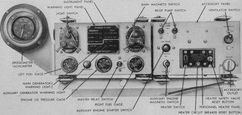
The new driver's instrument panel is labeled in this picture. (Picture from TM 9-718 Medium Tanks M46 and M46A1.)
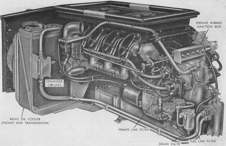
Obvious differences in the AV-1790-5B included the new engine wiring junction box and the additional fuel line filter. Also visible on the right oil cooler is one of the two new oil cooler fan controllers. This one controlled the engine oil cooler fan. (Picture from TM 9-718 Medium Tanks M46 and M46A1.)
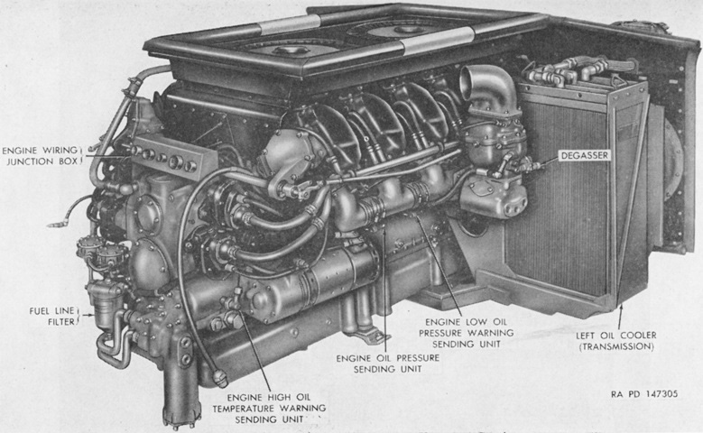
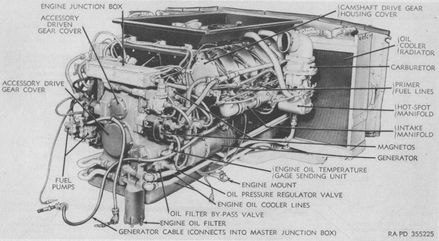
The new engine is seen from the opposite side. (Picture from TM 9-718 Medium Tanks M46 and M46A1.)
The new transmission oil cooler fan controller was attached to the left side of the CD-850-4. While the CD-850-3 transmitted power via both a mechanical path and hydraulically through the torque converter, the CD-850-4 delivered power totally through an hydraulic path. (Picture from TM 9-718 Medium Tanks M46 and M46A1.)
The oil coolers and lines were rearranged: the left cooler's three cores and the rear core of the right cooler were used for cooling the transmission oil, while the forward two cores of the right cooler were used for engine oil. A new gasoline-burning personnel heater was used, and oil lines were consequently not sent into the crew compartment from the coolers. (Picture from TM 9-718 Medium Tanks M46 and M46A1.)
Beginning with M46A1 serial number 1103, the second and fourth return rollers on each side were eliminated, yielding a suspension setup similar to that found on the 90mm gun tank M47. (Picture from ORD 9 SNL G-244 List of All Service Parts of Tank, Medium, M46 and M46A1.)
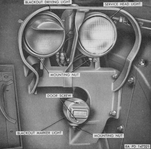
The headlights were mounted directly on the hull: a blackout driving light was mounted beside the service head light, with the blackout marker light below. (Picture from TM 9-718 Medium Tanks M46 and M46A1.)
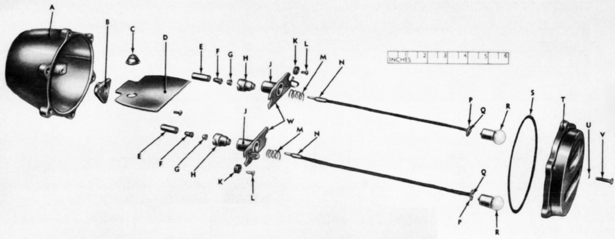
The new taillight design is shown expanded here. (Picture from ORD 9 SNL G-244 List of All Service Parts of Tank, Medium, M46 and M46A1.)
The fixed fire extinguishers in the M46A1 used three discharge nozzles, and the portable fire extinguishers were changed to 5lb (2.3kg) types. (Picture from TM 9-718 Medium Tanks M46 and M46A1.)
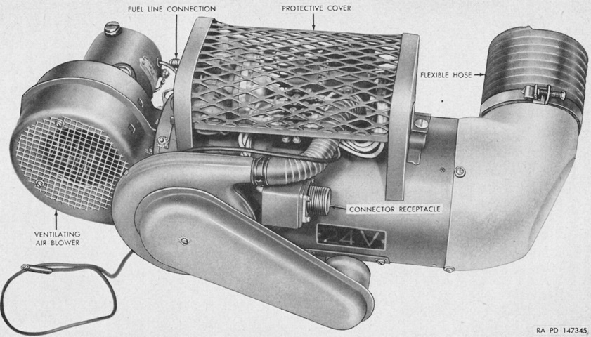
The Stewart Warner 978M-R24 heater replaced the earlier transmission oil-fed crew compartment heater. It burned gasoline from the main engine tanks in a combustion chamber, using 1gal (3.8L) every 4 hours on the high setting and 1gal (3.8L) every 8 hours on low. (Picture from TM 9-718 Medium Tanks M46 and M46A1.)
