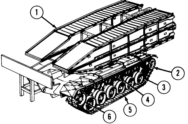
Armored Vehicle Launched Bridge M48A5.
The vehicle is shown here with the bridge stowed. 1. Bridge. 2. Final drive sprocket. 3. Roadwheel. 4. Support roller (either 3 or 5). 5. Track. 6. Compensating idler wheel. (Picture from TM 5-5420-226-10 C9.)
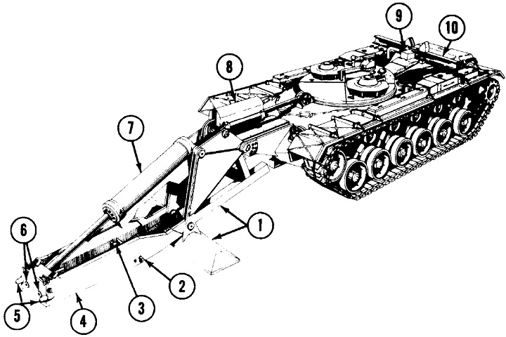
The vehicle is shown here with the launcher extended and bridge absent. 1. Boom and outrigger. 2. Guide pin. 3. Locking cylinder. 4. Tongue. 5. Pintles. 6. Ejection cylinders. 7. Tongue cylinder. 8. Overhead cylinder. 9. Holddown cylinder. 10. Bridge seat. (Picture from TM 5-5420-226-10 C9.)
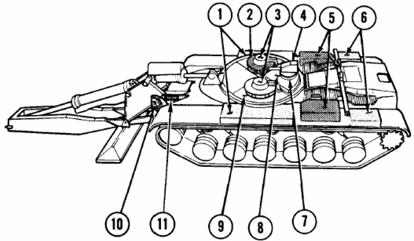
1. Front fender stowage boxes. 2. Commander's cupola. 3. Hatches. 4. Antenna mount. 5. Engine air cleaners. 6. Rear fender stowage boxes. 7. Ventilating blower cover. 8. Hydraulic oil reservoir. 9. Operator's cupola. 10. Smoke grenade discharger. 11. Smoke grenade stowage boxes. (Picture from TM 5-5420-226-10 C9.)
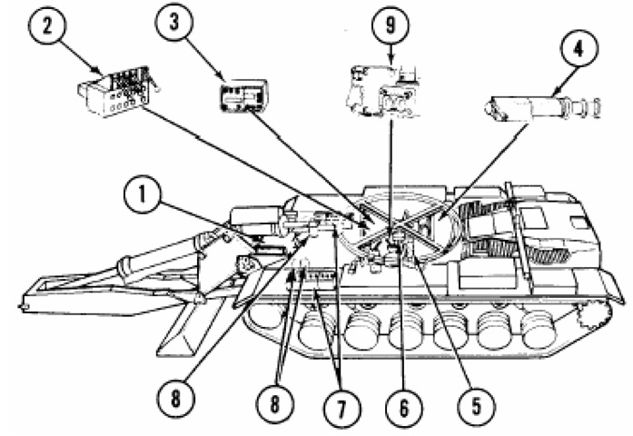
The location of select major components is diagrammed here. Compared to the gun tank, the batteries were relocated to in front of the AVLB's crew compartment. 1. Personnel heater. 2. Valve bank control. 3. Radio. 4. Power take off, pump-clutch assembly, pump-ball valve (hydraulic electrical upgrade). 5. Operator's master control panel. 6. Indicator panel. 7. Batteries (6). 8. Fire extinguishers (3). 9. Grenade launcher controls. (Picture from TM 5-5420-226-10 C9.)
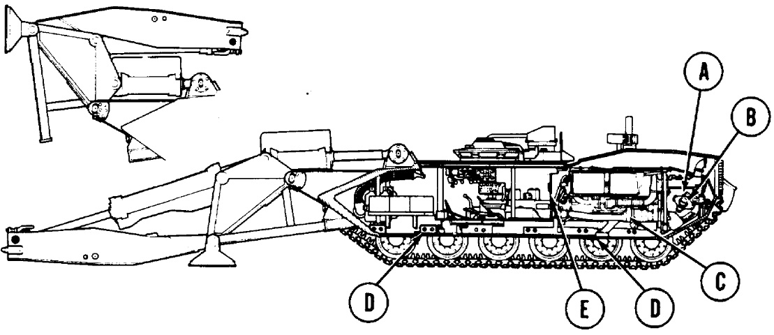
The locations of interior components can be seen here. A. Transmission. B. Universal joint. C. Engine with power takeoff. D. Hull drain valves. E. Engine air cleaner intake. (Picture from TM 5-5420-226-20-1 C8.)
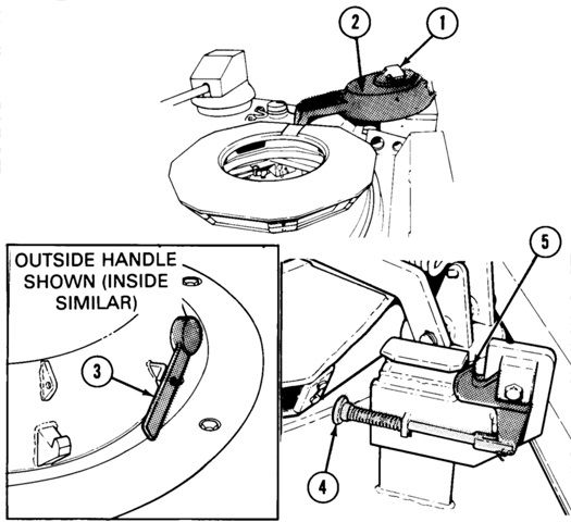
The commander and operator had identical cupolas above their positions. Parts of the late-type cupola are labeled in these sketches. 1. Periscope door assembly. 2. Cupola cover. 3. Cover handles. 4. Release knob. 5. Safety latch. (Picture from TM 5-5420-226-10 C9.)
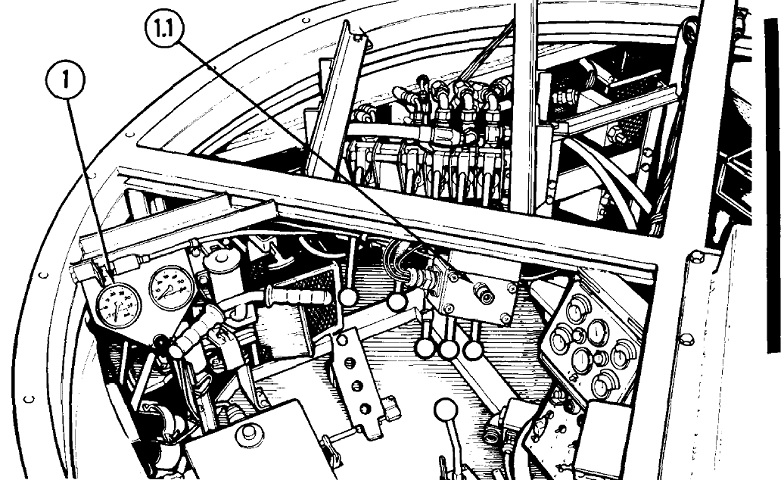
The operator's station is drawn here. 1. Tachometer and hour meter. 1.1. Dust detector warning lamp (if equipped).
The fixed fire extinguisher activation handle is visible above the right-hand grip of the handlebar-like steering control. The perforated accelerator pedal can be seen on the floor, and the brake pedal is diagonally up and to the left of the accelerator pedal, visible between it and the right-hand grip of the steering control. The headlight dimmer switch is to the left of the accelerator pedal, and the transmission shift lever is to the driver's right in the lower right of the image. The five handles facing the driver are the bridge operating controls. From left to right, they are the Eject lever, which controls the ejection cylinders; the Lock lever, which controls the locking cylinder; the Scissors lever, which controls the bridge scissors cylinder; the Tongue lever, controlling the tongue; and the Overhead lever, which controls both the overhead and holddown cylinders. (Picture from TM 5-5420-226-10 C9.)
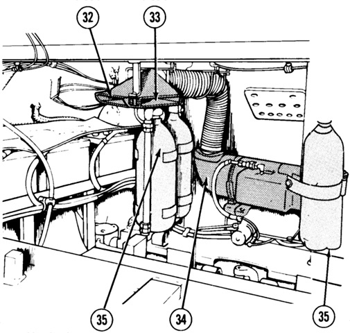
The interior of the front hull is shown in this sketch. 32. Operator's heater vent. 33. Commander's heater vent. 34. Personnel heater. 35. Fire extinguishers.
The portable fire extinguisher was stowed in a bracket behind the operator's seat. Three batteries can be seen on the left of the image; the other three were similarly placed on the right side of the hull. (Picture from TM 5-5420-226-10 C9.)
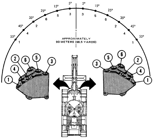
The pattern of launch of the smoke grenades is diagrammed here. Two buttons were provided: pushing the left button activated tubes 1, 2, and 5 from the left launcher and 4, 6, and 3 from the right. The right button activated the opposite tubes, and pushing both buttons fired the complete salvo. (Picture from TM 5-5420-226-10 C9.)
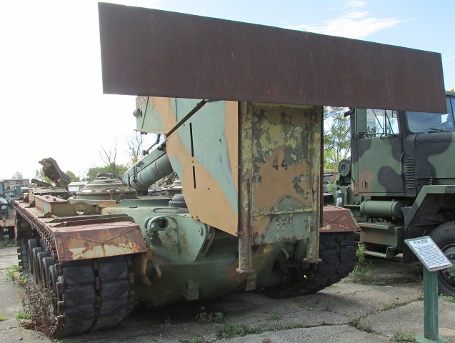
Compared to the above drawings from the manuals, this machine uses an earlier variant of the bridge launching apparatus and earlier cupolas with rear-hinged doors instead of the swiveling hatches. It was originally an M48A2C hull and consequently has three return rollers, but the presence of air cleaners on the rear fenders indicate that is has been upgraded to the diesel engine.
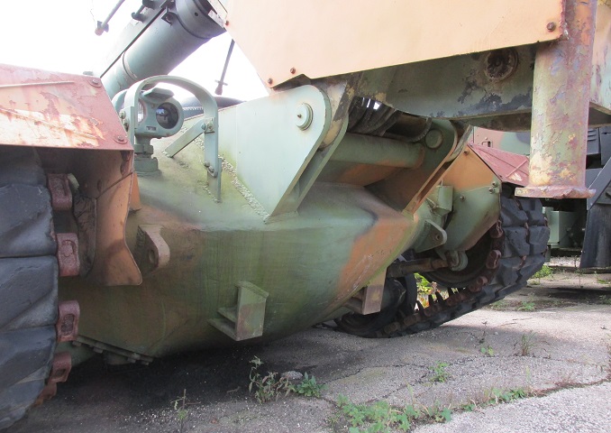
The stout attachments on the hull front for the bridge boom can be seen in this angle, as well as the stops welded to the lower hull front that meet with similar pads on the boom.
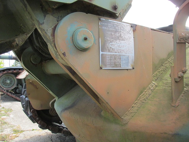
A placard for transportation data was attached to the left-hand mount for the bridge boom.
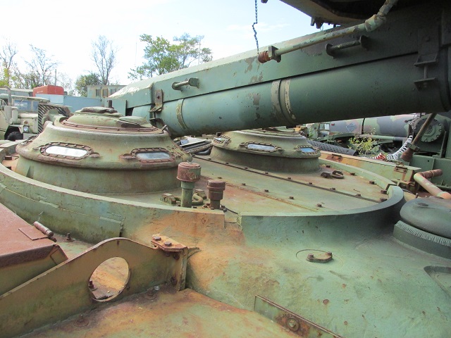
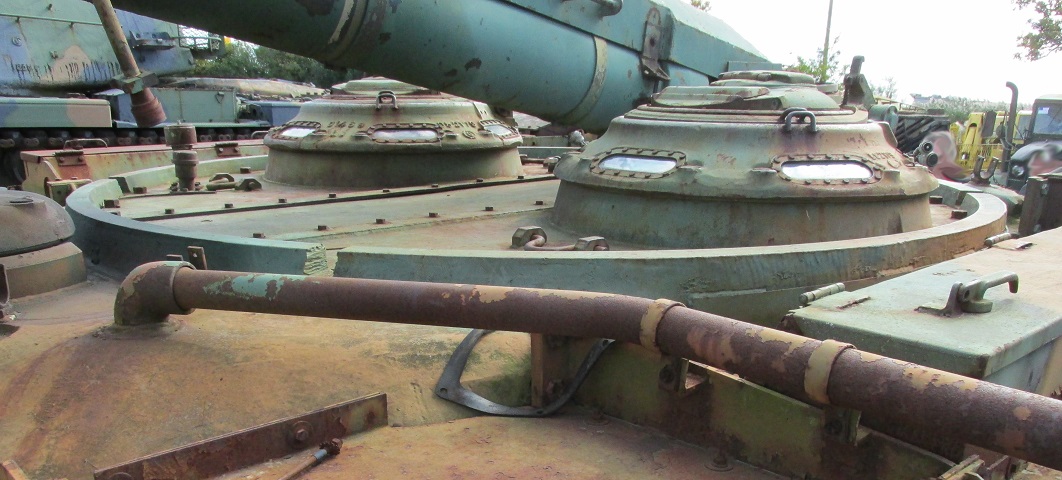
The turret ring was plated over, and the commander and operator were provided with vision cupolas that could accept infrared periscopes. Compared to the drawings above, this earlier design had the overhead cylinder anchored behind the cupolas instead of in front of them. Likewise, a ventilator can be seen on the hull roof where the driver's hatch originally would have been; this was placed behind the cupolas when the launching apparatus was redesigned.
Though upgraded to M48A5 status automotively, this vehicle retains the M48A2C-style personnel heater with its left-side exhaust.
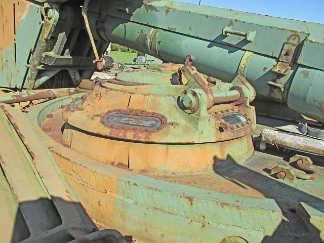
The rear of the operator's cupola is detailed here, with the overhead cylinder beside it. Armor protected the overhead cylinder hose on top.
The ventilator dome replaced the normal driver's hatch, and the periscope openings were also filled in. Just above the hull lifting eye is a guard that houses handles for fire extinguisher activation.
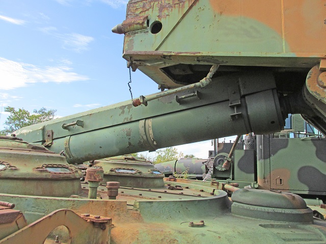
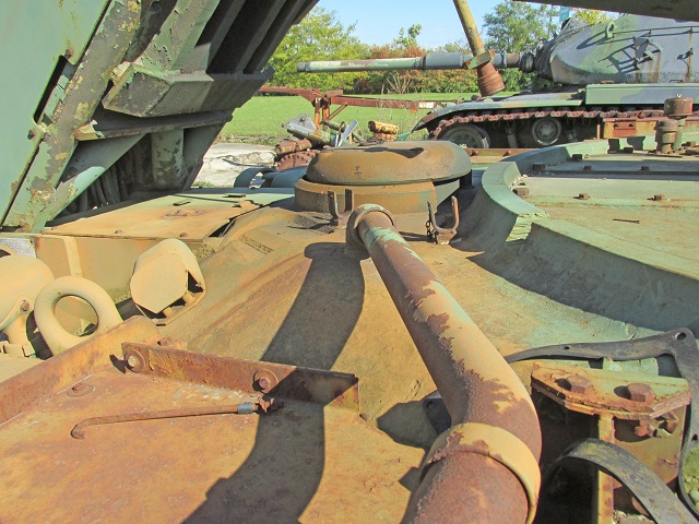
The overhead cylinder and tongue can be seen here. The pyramid-shaped pintles at the end of the tongue meshed with holes in the bridge and ensured that the bridge and tongue were lined up and secure for retrieval. The hoses hanging down on each side of the tongue would be attached to the bridge, and were fitted with quick-release couplings which would allow the launcher to disconnect from the bridge by simply backing away. The plugs would need to be manually attached to the bridge upon retrieval.
Both pintles can be seen from this angle, along with the ejection cylinder that helped free the launcher from the bridge.
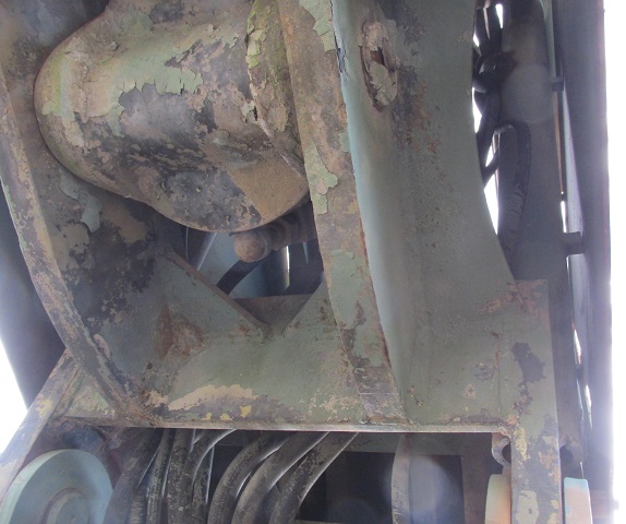
A look up inside the plating around the boom is provided here, showing the numerous hydraulic lines and the base of the tongue cylinder.
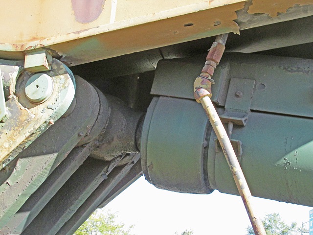
The end of the overhead cylinder is shown in this image, and the tongue cylinder can be seen above.
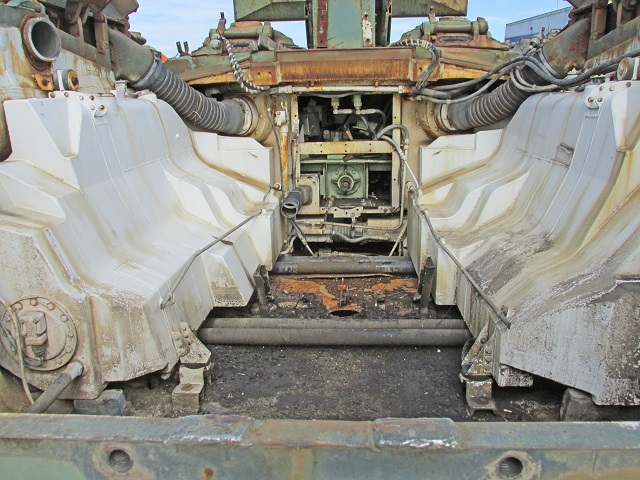
This vehicle had its engine removed for maintenance, providing a view of the empty engine compartment. White fuel tanks occupy both sides, and torsion bars can be seen just above the floor. The road wheels on each side are slightly offset from each other due to the fact that the torsion bars stretch the entire width of the hull. The large black flexible hoses on each side transport air from the crew compartment to the engine air cleaners, thence to the turbocharger elbows. The aperture from the air cleaner can be seen above the fuel tank at the upper left. The firewall has also been removed, and the crew compartment interior can be seen.
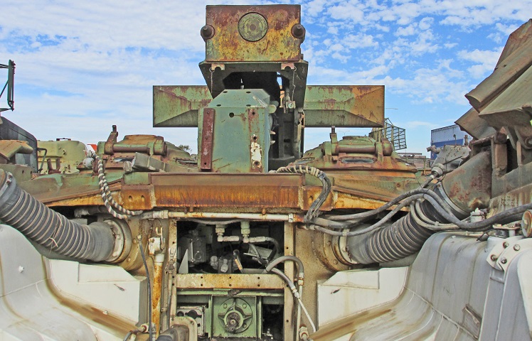
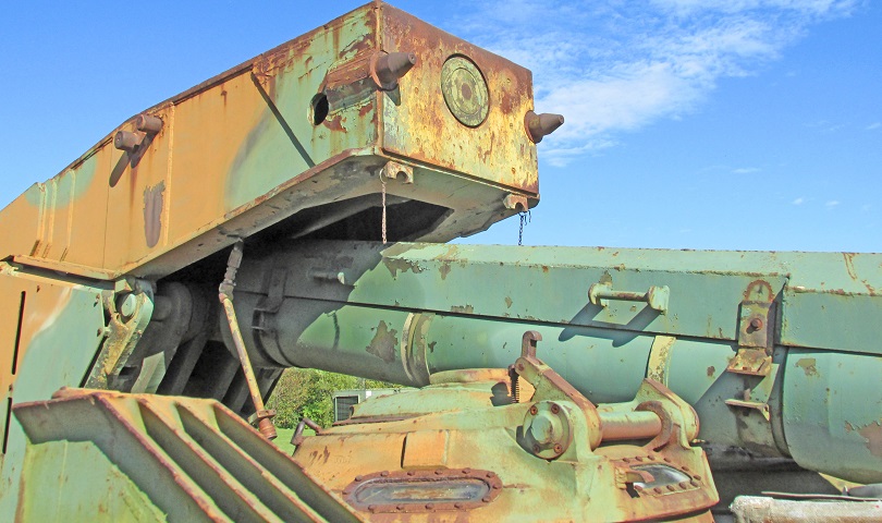
The bridge tongue is visible at the top of this image, with the pintles on each side and the ejection cylinder in the center. The rear of the overhead cylinder hose was also protected by armor.
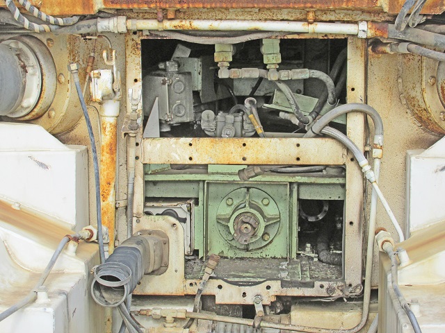
The power takeoff from the engine is centered in the lower portion of the open firewall, and the flexible black hose to the left connected to the engine generator air intake tube.
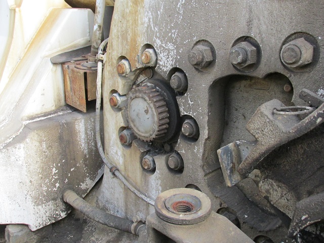
Seventeen studs attached each final drive assembly to the hull; eight of which surrounded the outgoing pinion gear, as seen here. This vehicle has late-model final drives, differentiated by the geared adapter that fits over the inboard end of the pinion gear. The center of the earlier style was open, and the pinion gear itself could be seen inside. The pinion gear meshes with a larger drive gear, which is connected to the output shaft that goes to the drive sprocket hub. A transmission mount can be seen near the bottom of the image.
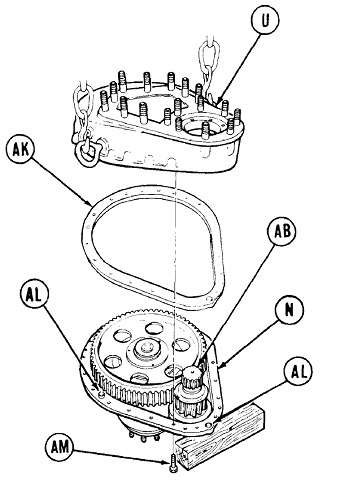
An exploded view of the final drive is shown here, ready for reassembly. The pinion gear referred to above is labeled AB, and the large drive gear with its six lightening holes is unlabeled. U is the case; AK is a gasket; N is the final drive carrier; AL are dowel pins to help align the case; AM are bolts. The nut that secured the drive gear to the output shaft was secured by 1100-1500lb-ft (1500-2000N m) of torque. (Picture from TM 5-5420-226-34 C4.)
