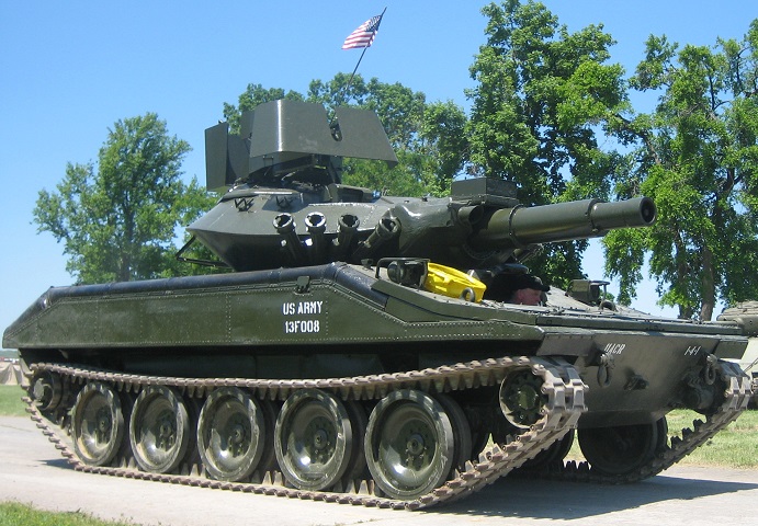
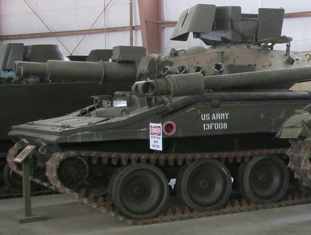
152mm Gun-launcher Armored Reconnaissance/Airborne Assault Vehicle M551 Sheridan.
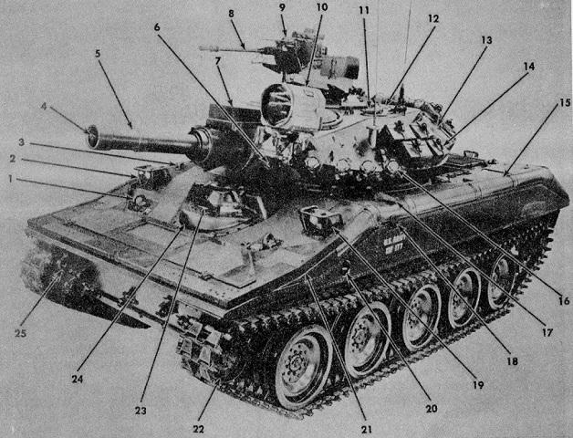
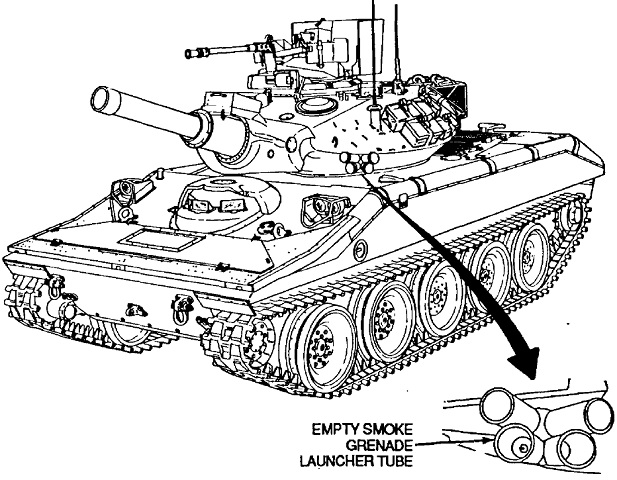
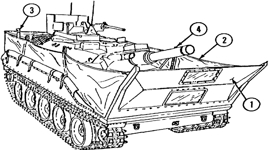
The front of the vehicle is illustrated here. It lacks a bore evacuator and appears to have an applique armor mine kit installed, visible on the bottom of the front hull. Also, note the location of the turret ventilator, visible behind the searchlight. 1. Front lifting eye (2). 2. Right front headlight assembly. 3. Personnel heater exhaust outlet. 4. Muzzle plug. 5. 152mm gun-launcher. 6. 7.62mm coaxial machine gun. 7. Missile subsystem transmitter door. 8. Cal. .50 machine gun. 9. Commander's ballistic shield (TOE kit). 10. Searchlight (TOE kit). 11. Loader's M37 periscope. 12. Loader's hatch cover. 13. Water can. 14. Cal. .50 machine gun ammunition. 15. Left side flotation barrier cover. 16. XM176 grenade launcher. 17. Front bilge pump outlet. 18. Flotation barrier step. 19. Left front headlight assembly. 20. Fixed fire extinguisher exterior actuating handle. 21. Flotation surfboard. 22. Dual idler wheel (2). 23. M47 periscope (3) or M48 periscope (1) in center position for night vision. 24. Driver's rotatable hatch cover. 25. Front tow shackle (2). (Picture from TM 9-2350-230-12.)
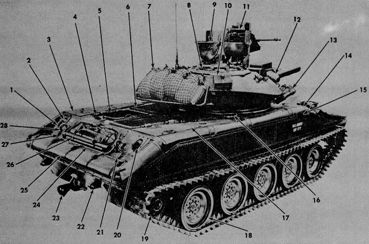
The rear of the machine is detailed in this image. 1. Intercom set access door. 2. Left rear taillight assembly. 3. Engine air cleaner access door cover. 4. Engine exhaust outlet. 5. Engine compartment exhaust grille (2). 6. Engine compartment air intake grille. 7. Turret stowage rack. 8. Vision block (10). 9. Commander's split hatch cover. 10. Cal. .50 ammunition. 11. Night vision sight (TOE item). 12. XM44/E1 periscope ballistic cover. 13. XM176 grenade launcher. 14. Right side flotation barrier cover. 15. Flotation barrier step. 16. Fuel filler cap cover (2). 17. Battery access door cover. 18. Dual road wheel (10). 19. Dual drive sprocket wheel (2). 20. Right rear taillight assembly. 21. Engine compartment bilge pump outlet. 22. Rear towing shackle (2). 23. Towing pintle. 24. Tow cable. 25. Rear flotation barrier cover. 26. Pioneer tools. 27. Engine compartment access cover. 28. Rear lifting eye (2). (Picture from TM 9-2350-230-12.)
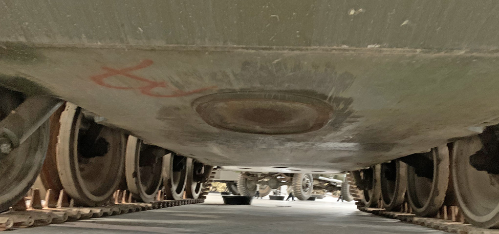
The driver had an escape hatch in the hull floor. Also visible on left of this image is the shock absorber connected to the right front road wheel.
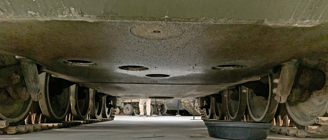
The hull bottom is seen from the rear. Five drain/access plugs were scattered about the hull rear floor, and these as well as the the driver's escape hatch needed to be secured before operating the vehicle in water. Both rear shock absorbers are in the frame.
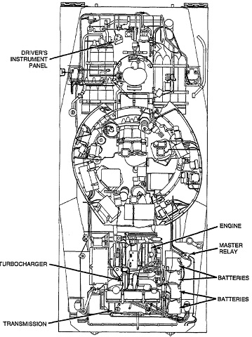
This ghosted view shows the location of various powertrain components as well as ammunition stowage. (Picture from TM 9-2350-230-20-1.)
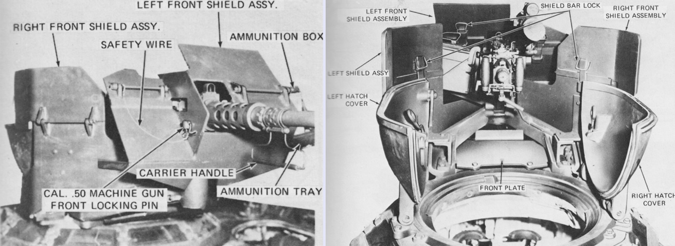
The commander's ballistic shield plates are labeled from the front and rear, respectively. When a cupola with the kit was traversed on slopes, the weight of the kit could cause the cupola to continue rotating after the rotation switch had been released. Momentarily actuating the switch in the opposite direction would stop the cupola and allow the brake to engage. (Picture from TM 9-2350-230-10.)
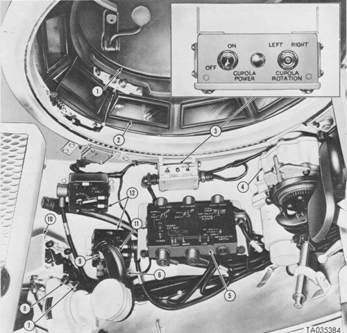
These are the controls for the commander's power-assisted cupola, viewed from outside in the top image and inside in the bottom. The cupola had a rotation switch on the control assembly which was pressed to the left or right to traverse the cupola, and a ratcheting handle was provided for emergency manual use. Some vehicles had left or right buttons instead of the switch. A cupola align switch was added to the M551A1 in order to bring the cupola and attached laser rangefinder into approximate alignment with the gun-launcher. The cupola could only be used continuously for two minutes followed by a ten-minute rest period. 1. Split hatch cover. 2. Vision block (10). 3. Cupola control assembly. 4. Cupola traverse mechanism. 5. AM-1780/VRC audio frequency amplifier. 6. Turret and gun-launcher power control handle. 7. Elevation trim button. 8. Traversing trim button. 9. 152-mm gun/launcher and 7.62-mm machine gun firing trigger. 10. Grenade projector control panel. 11. Palm switch. 12. C-2298/VRC intercom set control. (Picture from TM 9-2350-230-10.)
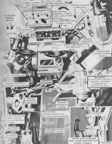
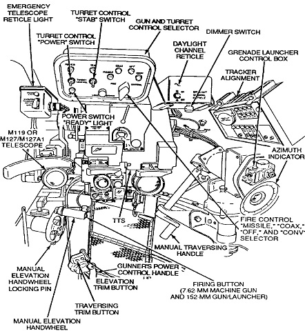
The gunner's controls and instruments are shown in this picture. (Picture from TM 9-2350-230-10.)
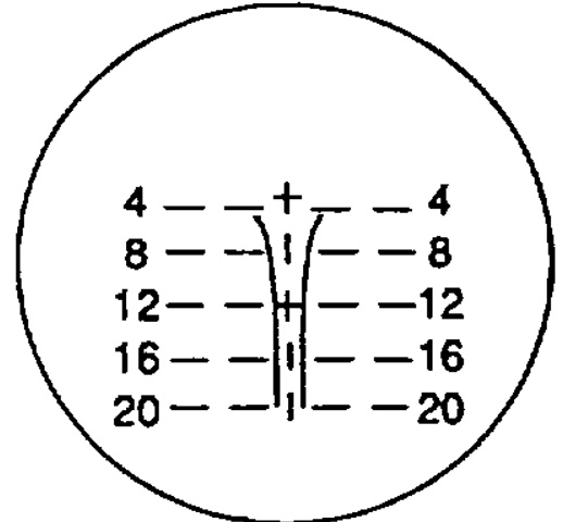
The gunner's passive infrared periscope M44 was used with conventional ammunition only. It offered 9x magnification or a unity window, and its 9x reticle pattern is illustrated here. (Picture from TM 9-2350-230-10.)
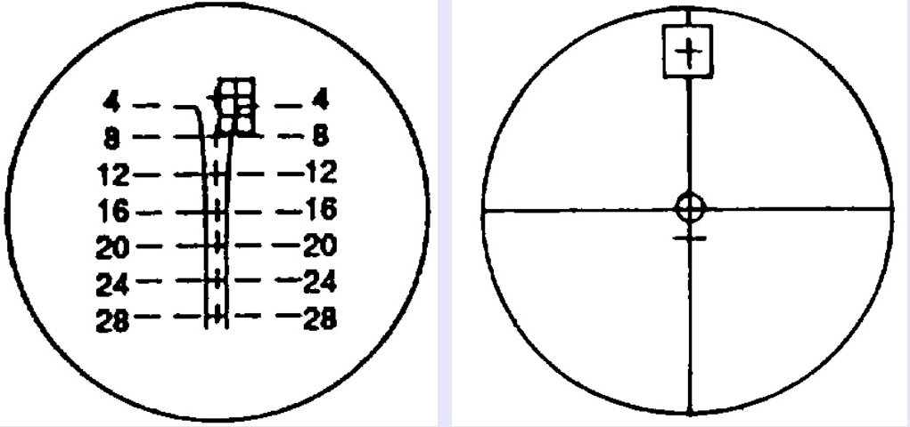
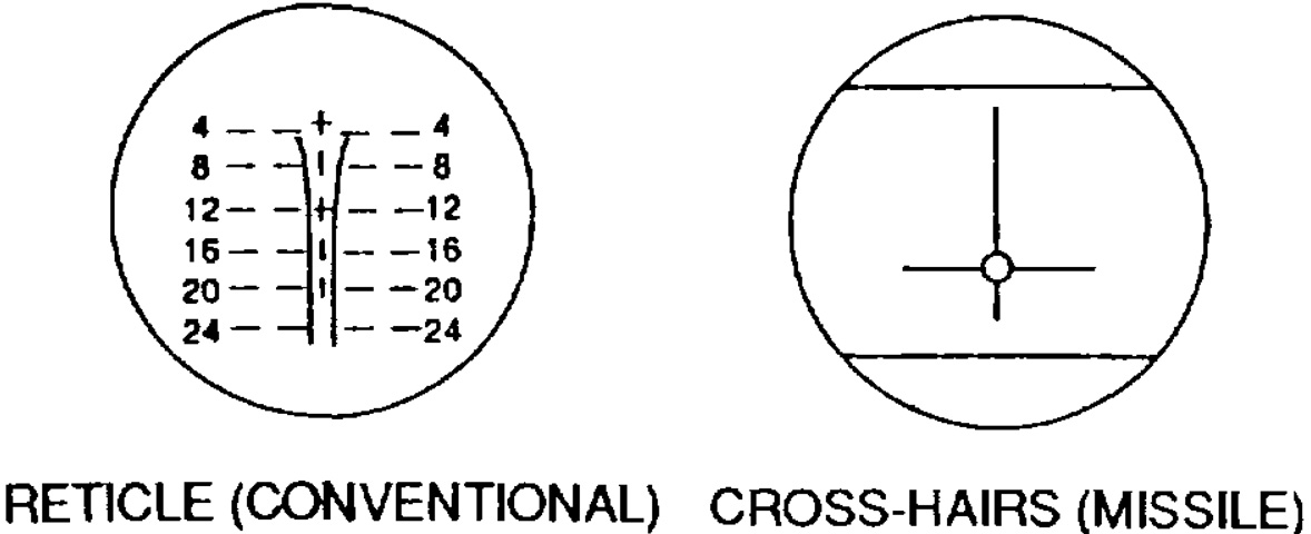
The gunner's telescope M127 or M127A1 could be used at either 8x or 12x magnification, and for either conventional ammunition or missiles. The conventional reticle is on the left; the shape in the upper right was being used to illustrate boresighting procedure. The missile reticle is on the right. The horizontal line below the crosshair on the missile reticle was an interference line. If obstacles appeared above this line or were directly in the line-of-sight, the vehicle was to be moved to another position before the missile was fired. (Picture from TM 9-2350-230-10.)
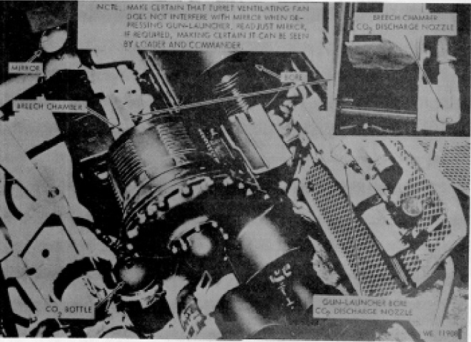
The open-breech scavenging system is shown here. The mirror allowed the loader and commander to visually check the breech for remnants of the combustible casing. The gas nozzles tended to blow any remnants into the fighting compartment, however. (Picture from TM 9-2350-230-12.)
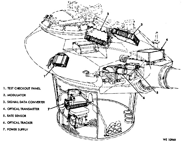
The various missile subsystem units are sketched here. The optical tracker tracked the missile in flight, saw how far it deviated from the light of sight, and sent this information to the signal data converter. The rate sensor tracked the rate of turret traverse and gun-launcher elevation and sent this information to the signal data converter. The signal data converter combined the output from the tracker with turret traverse and gun-launcher elevation rate information taken from the rate sensor in order to calculate corrections to keep the missile on target. These corrections were then sent to the modulator as missile command signals. The modulator converted signals received from the signal data converter to high current output to operate the transmitter. The optical transmitter changed these high current electrical signals to infrared signals, which were transmitted to the missile as a narrow infrared beam. The test checkout panel initiated lamp and meter test, which ensured that all lamps on the test checkout panel and the test checkout panel null meter were operating; transmitter test, which checked the operation of the transmitter and both transmitter lamps; tracker alignment test, which aligned the gunner's telescope reticle and the tracker; and system self test, which displayed a green go lamp or a red no go lamp depending on its analysis of the guidance and control system. (Picture from TM 9-2350-230-12.)
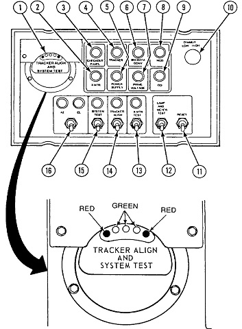
The test checkout panel is detailed here. 1. Electronic null indicator [indicated alignment of checksight source during tracker alignment test; indicated operational condition of rate sensing unit]. 2. XMTR lamp [indicated transmitter was not operational during system self-test]. 3. CHECKOUT PANEL lamp [indicated checkout panel was not operational during system self-test]. 4. TRACKER lamp [indicated tracker was not operational during system self-test]. 5. POWER SUPPLY lamp [indicated power supply was not operating]. 6. SIG DATA CONV lamp [indicated signal data converter was not operational during system self-test]. 7. PRIME VOLTAGE lamp [indicated vehicle power was low]. 8. MOD lamp [indicated modulator was not operational during system self-test]. 9. GO lamp [indicated guidance and control system was operating at end of self-test]. 10. DIMMER control [controlled brightness of all but NO/GO lamps]. 11. RESET switch [turned off all control signals; reset guidance and control system]. 12 LAMP AND METER TEST switch [initiated test of all lamps and null meter on this panel]. 13. XMTR TEST switch and lamp [started transmitter test]. 14. TRACKER ALIGN switch and lamp [started tracker alignment test]. 15. SYSTEM TEST switch and lamp [started system self-test]. 16. AZ/EL switch and lamps [selected azimuth and elevation signals from rate sensing unit for test; indicated azimuth and elevation alignment during tracker alignment test]. (Picture from TM 9-2350-230-10 C2.)
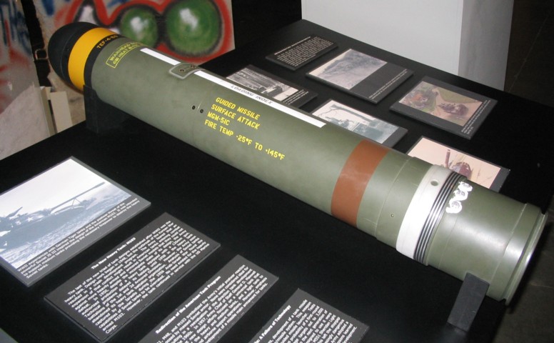
The MGM-51C missile had a range of ~3,000m (~3,300yd), was 41.5" (105cm) long, and weighed ~61lbs (28kg). The shorter key on the MGM-51C (0.075" versus 0.130" [0.191cm versus .330cm])reduced stress on the gun barrel that had been causing fatigue cracks with the earlier, taller keyways. This allowed the gun tubes to be used for 600 conventional round firings, compared to 200 with the taller keyways.
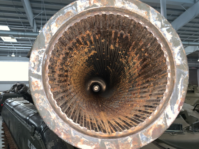
The keyway for the missile's index key can be seen at the 6:00 position on the gun-launcher tube. It is the channel cut straight through the rifling all the way to the breech.
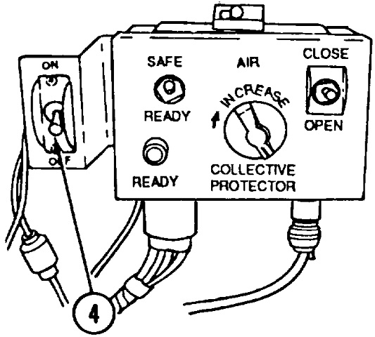
The loader's panel contained the on/off switch for the closed-breech scavenging system (CBSS) compressor (4), the weapon safe/ready switch, the control for the crew's collective NBC filtration system, and the switch to open and close the gun/launcher breech electrically. (Picture from TM 9-2350-230-10 C2.)
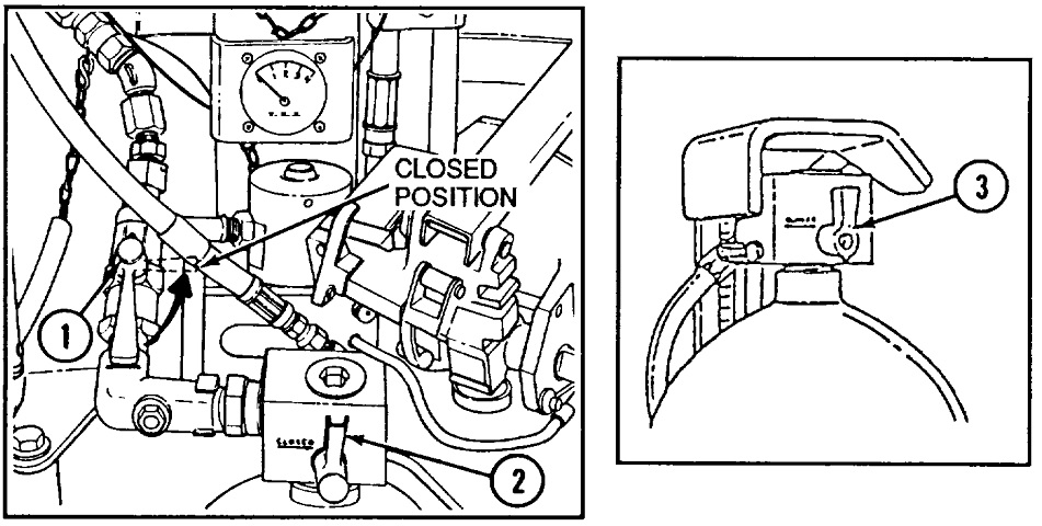
Other CBSS controls included the air shutoff valve (1), and front (2) and rear (3) manifold shutoff valves. (Picture from TM 9-2350-230-10 C2.)
This view shows the M551's unusual driver's hatch in the open position. The hatch rotated around the driver, removing the need for an adjustable-height seat for open-hatch operation, and also eliminating the worry of turret rotation over the driver's exposed head. The black container on the hatch to the mannequin's right is the periscope washer fluid reservoir.
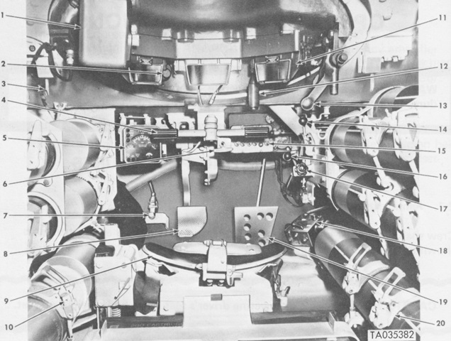
The driver's compartment is illustrated in this image. His seatback is folded forward onto the seat bottom. The water steer lever was pushed forward to the "WATER" setting when entering water, and pulled back to the "LAND" setting upon reaching land. 1. Periscope washer liquid reservoir. 2. Periscope washer pump. 3. Hatch cover hold-open lock. 4. Steer bar. 5. Indicator panel. 6. Parking brake lock handle. 7. Headlight dimmer switch. 8. Brake pedal. 9. Driver's seat. 10. Conventional ammunition stowage rack. 11. M47 periscope (3). 12. Hatch cover handle grip. 13. Hatch cover locking lever. 14. Transmission shift lever. 15. Driver's switch panel. 16. Water steer lever. 17. Hand throttle control knob. 18. C-2297/VRC intercom set. 19. Accelerator pedal. 20. Missile stowage rack. (Picture from TM 9-2350-230-10.)
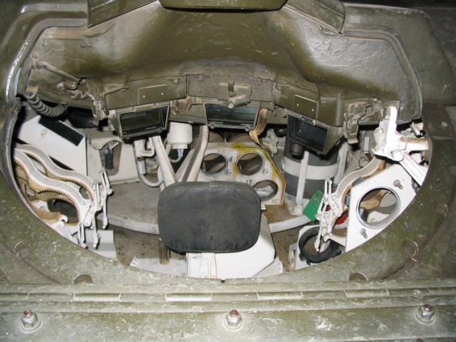
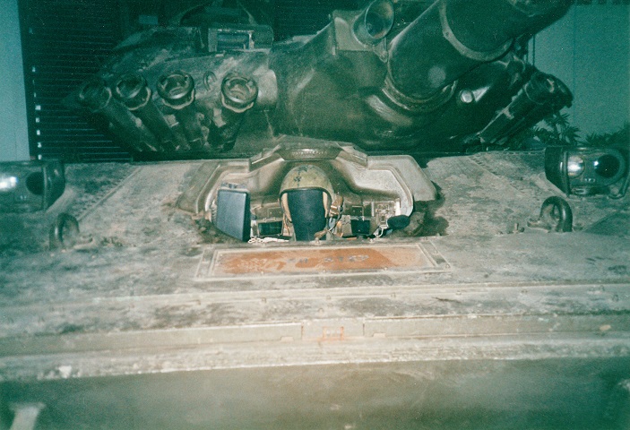
A look inside the driver's position is offered here. The driver's three M47 periscopes are mounted, and the center one could be replaced with an infrared periscope M48. The periscope washer fluid reservoir is now missing from this vehicle. To the driver's left is a conventional ammunition stowage rack, and a missile stowage rack is on his opposite side. The turret floor is visible behind the driver's seat back. The turret horizontal stowage rack for five conventional rounds can be seen on the turret floor.
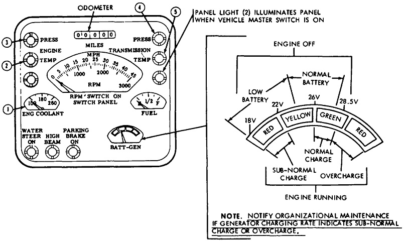
The driver's indicator panel is sketched in this drawing. 1. Engine coolant temperature gage. 2. Engine coolant temperature warning light. 3. Engine low oil pressure warning light. 4. Transmission low oil pressure warning light. 5. Transmission oil temperature warning light. (Picture from TM 9-2350-230-12.)
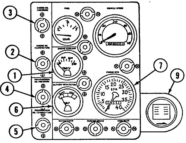
The driver's indicator panel was changed during production to this design. 1. Engine coolant gauge. 2. Engine temperature light. 3. Engine oil pressure light. 4. Transmission oil pressure light. 5. Transmission temperature light. 6. Battery/generator gauge. 7. Tachometer. 9. Air filter restriction gauge. (Picture from TM 9-2350-230-10 C2.)
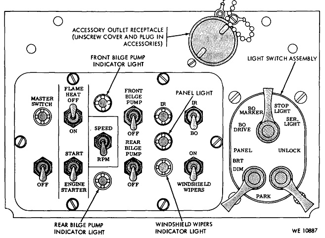
The driver's switch panel is labeled in this drawing. (Picture from TM 9-2350-230-12.)
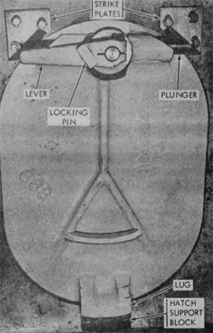
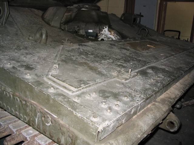
The driver's floor escape hatch was released by unscrewing the locking pin then rotating the lever toward the center of the hatch. (Picture from TM 9-2350-230-12.)
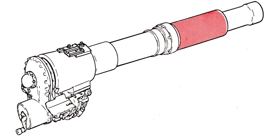
A 152mm gun-launcher M81 Modified is sketched with the bore evacuator shaded red. Its overall length was 116" (295cm), and it weighed 1,125lb (510.3kg) without the bore evacuator. (Picture from TM 9-2350-230-10.)
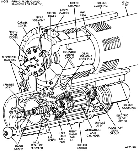
The internals of the gun-launcher breech are drawn here. The breech could be opened manually with the hand crank by snapping the locking lever into the spindle slot at the center of the handle attachment. When opened electrically, the locking lever was to be snapped into any of eight slots in the breech rear cover, which would disengage the hand crank from spinning when the breech opened automatically. (Picture from TM 9-2350-230-35/2 C13.)
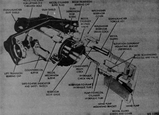
Details of the gun-launcher mount are shown here. (Picture from TM 9-2350-230-12.)
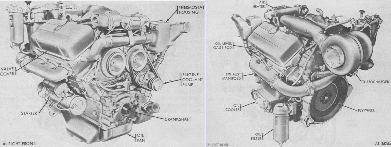
A 6V53T engine with an aluminum cylinder block is seen from the right front on the left and the left rear on the right. (Picture from TM 9-2815-205-34 C2.)
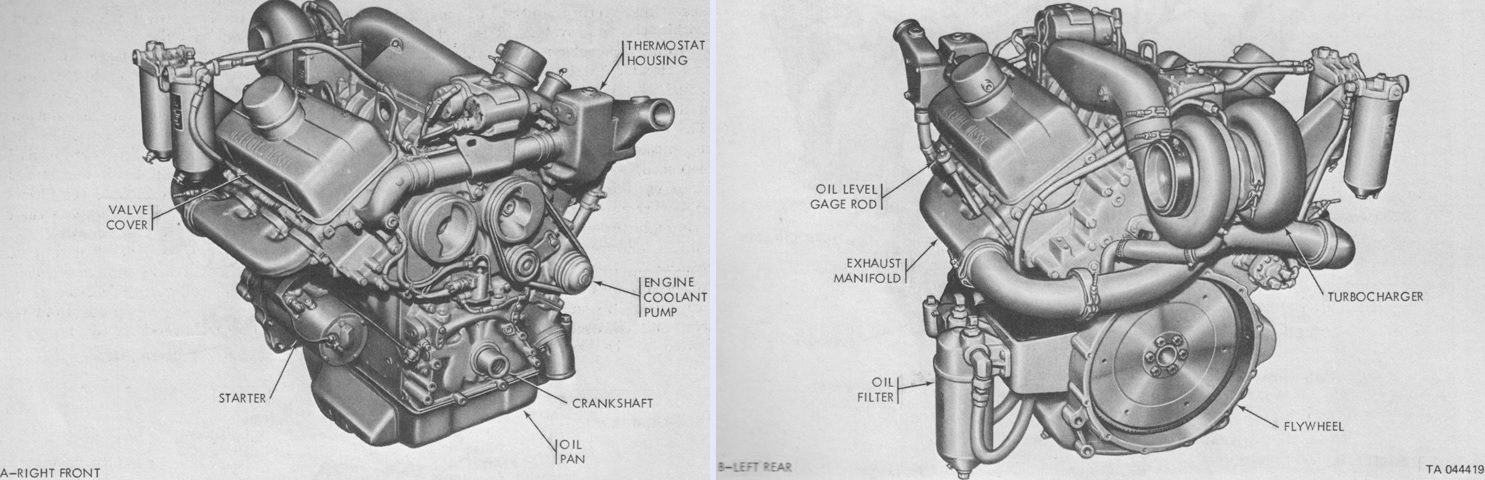
A 6V53T engine with an iron block is displayed from the same angles. The engine was 44⅞" (113.98cm) long, 36⅝" (93.028cm) wide, and 38½" (97.8cm) high. (Picture from TM 9-2815-205-34 C2.)
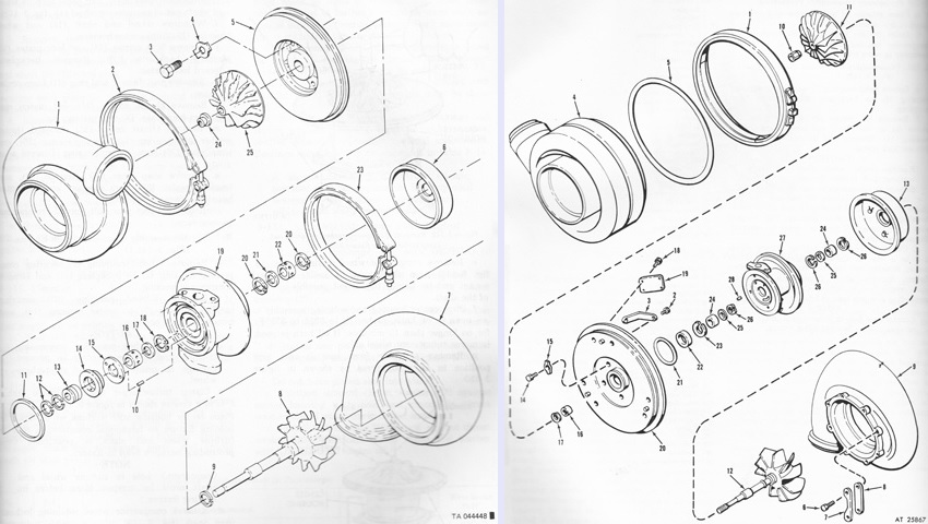
The turbocharger used on engines with a cast-iron block is on the left, and can be contrasted with the one on the right, used with aluminum block engines. The turbocharger compressor minimum discharge pressure for aluminum block engines was 21 inHg (.71 bar), while that for iron block engines was 28 inHg (.95 bar). The legend for the left image is: 1. Compressor housing. 2. Coupling. 3. Bolt. 4. Lock plate (4). 5. Backplate. 6. Turbine wheel shroud. 7. Turbine housing. 8. Turbine wheel and shaft. 9. Turbine end piston ring. 10. Spring pin (2). 11. Seal ring. 12. Piston ring (2). 13. Thrust spacer. 14. Thrust collar. 15. Outboard thrust bearing. 16. Bearing. 17. Wear washer. 18. Retaining ring. 19. Center housing. 20. Retaining ring (2). 21. Washer. 22. Bearing. 23. V-band coupling. 24. Locknut. 25. Compressor wheel.
The legend for the right image is: 1. Coupling. 2. Screw (6). 3. Lock plate (3). 4. Compressor housing. 5. Seal ring. 6. Screw (8). 7. Lock plate (4). 8. Clamp (8). 9. Turbine housing. 10. Nut. 11. Compressor wheel. 12. Turbine wheel and shaft. 13. Wheel shroud. 14. Screw (4). 15. Lock plate (4). 16. Spacer. 17. Seal ring. 18. Drive screw (4). 19. Name plate. 20. Back plate. 21. Seal ring. 22. Thrust collar. 23. Thrust washer. 24. Bearing (2). 25. Bearing washer (2). 26. Snap ring (3). 27. Center housing. 28. Spring pin. (Picture from TM 9-2815-205-34 C2.)
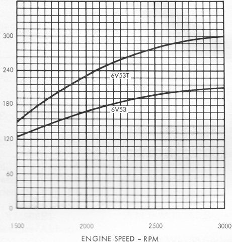
The horsepower performance curve for the 5063-5398 or 5063-5395 6V53T is drawn, alongside that for the naturally aspirated 6V53 found in the M113A1 and M113A2 armored personnel carriers. (Picture from TM 9-2815-205-34 C2.)
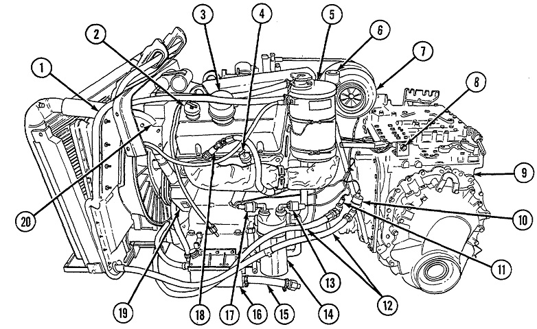
The combined engine and transmission are drawn from the left side. 1. Radiator coolant fan shroud. 2. Engine oil filler cap. 3. Crankcase breather cover. 4. Engine oil level gage. 5. Coolant surge tank. 6. Transmission oil level gage. 7. Turbocharger. 8. Electrical harness receptacle. 9. Transmission. 10. Transmission oil pressure switch. 11. Transmission oil temperature switch. 12. Transmission oil cooler hoses. 13. Engine oil low pressure switch. 14. Engine oil filter. 15. Air box heater drain hose. 16. Engine breather drain collector box. 17. Air cleaner blower relay switch (oil pressure). 18. Engine fuel return hose quick disconnect. 19. Engine coolant pump. 20. Inlet thermostat housing. (Picture from TM 9-2350-230-12.)
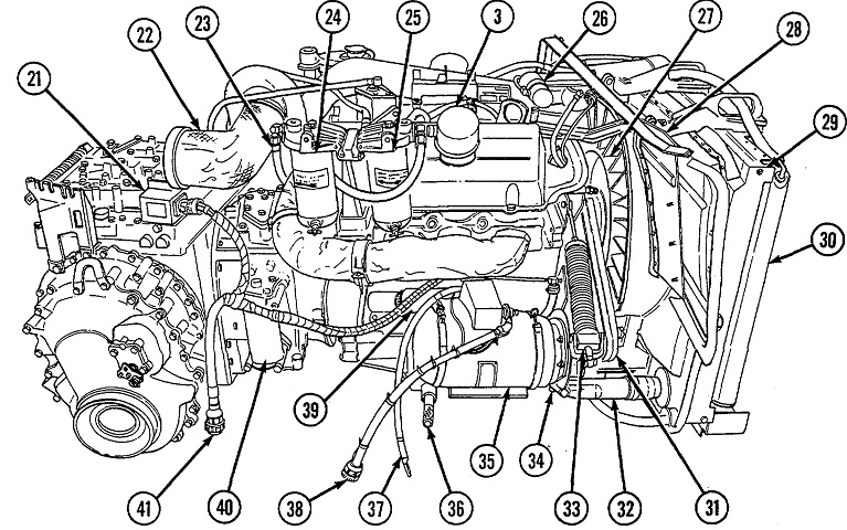
The opposite side of the powerplant is sketched here. 21. Starter relay box. 22. Engine exhaust elbow. 23. Main fuel hose. 24. Strainer. 25. Primary fuel filter. 26. Air box accumulator. 27. Radiator coolant fan. 28. Radiator cooling fan shroud. 29. Transmission oil cooler. 30. Radiator. 31. Generator/coolant fan drive belts. 32. Radiator outlet tube assembly. 33. Belt tensioner. 34. Coolant drain plug. 35. Generator. 36. Engine mount screw. 37. Powerplant to ground cable. 38. Generator-to-voltage regulator wiring harness. 39. Engine starter motor. 40. Transmission oil filter. 41. Starter-to-battery cable. (Picture from TM 9-2350-230-12.)
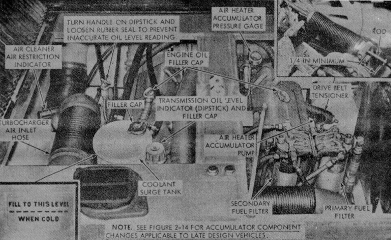
The engine compartment is pictured here. The 6V53T used a 17:1 compression ratio and was supplied with 21 quarts (20L) of oil and 44.5 quarts (42.1L) of coolant. (Picture from TM 9-2350-230-12.)
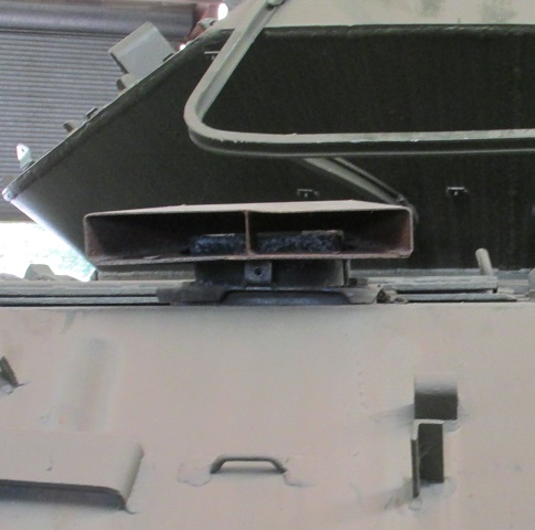
The engine exhaust was provided with a deflector that routed the gases to the rear.
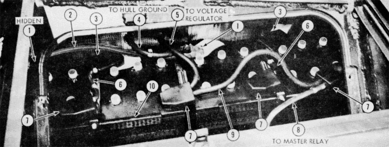
Two sets of two 12-volt batteries in series were connected in parallel to create a 24-volt system. 1. Negative terminal adapter (2). 2. Jumper, negative to negative. 3. Negative terminal adapter w/insulator (2). 4. Hull ground cable #10. 5. Voltage regulator lead #13. 6. Jumper, negative to positive (2). 7. Positive terminal adapter w/insulator (4). 8. Leads #11, #128, and #561. 9. Jumper, positive to positive. 10. Battery hold-down bracket group (2). (Picture from TM 9-2350-230-12.)
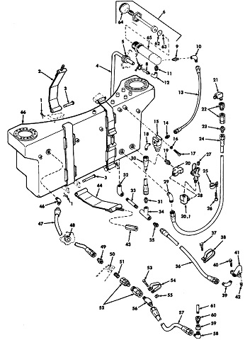
The fuel tank was located at the front of the engine compartment, behind the turret. The tank (66) and fuel lines and fittings are illustrated in this diagram. (Picture from TM 9-2350-230-12.)
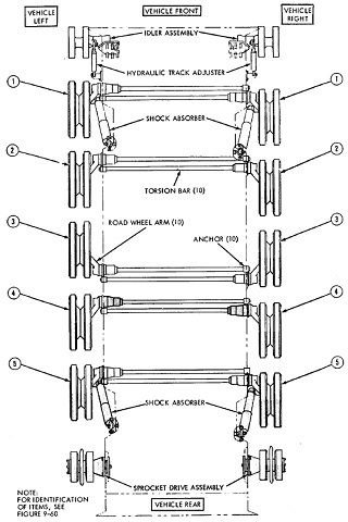
Parts of the suspension system are drawn in this image. The numbers refer to road wheel position. Note the orientation of road wheel number 3 on each side. (Picture from TM 9-2350-230-12.)
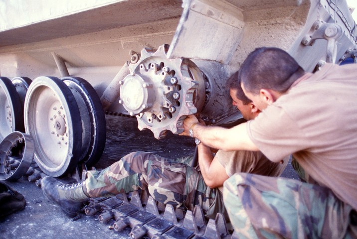
This image shows the Sheridan's center-drive sprocket and dual center guide track. These soldiers are repairing the tank following Operation Just Cause. (Picture taken 1 Dec 1989 by SGT. Joseph Garrison; available from the Defense Visual Information Center.)
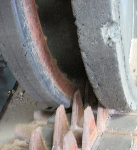
The double center guides of the T138 track are highlighted in this image.
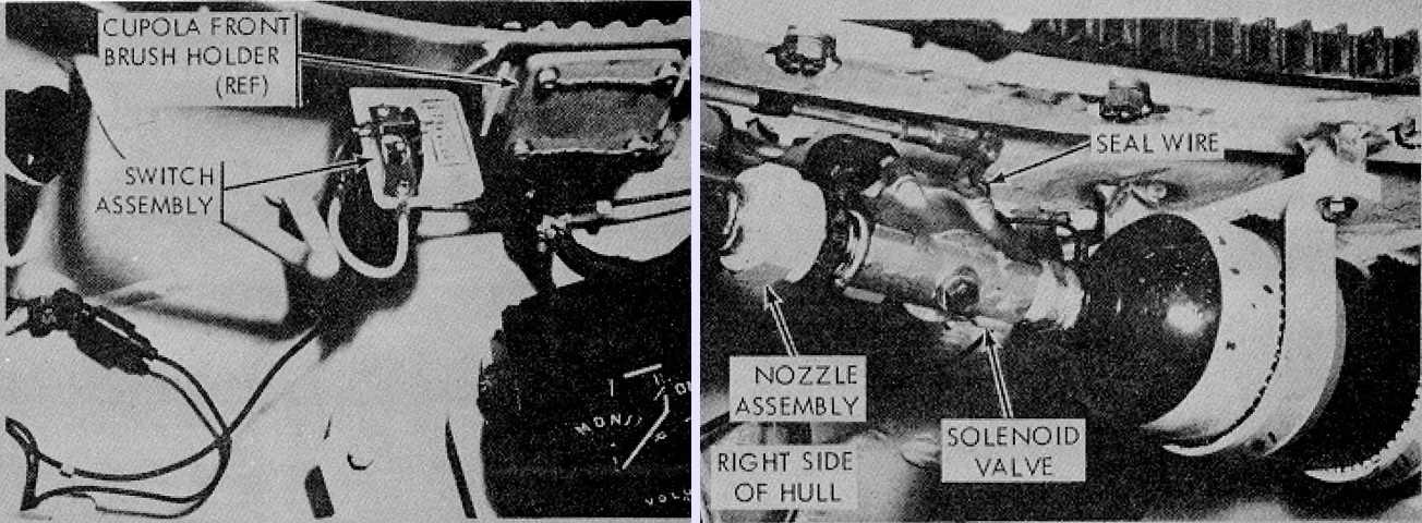
Two fixed fire extinguishers were installed, one for the crew compartment and the second for the engine compartment. The commander had access to an electrical switch that discharged the extinguisher for the crew compartment. (Picture from TM 9-2350-230-12.)
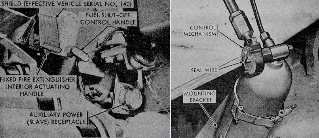
The driver's fire extinguisher actuating handle discharged both the crew compartment and engine compartment extinguishers. In addition, fuel was automatically cut to the engine. The exterior fire extinguisher handle also activated both of these extinguishers, but did not cut fuel to the engine. Besides these, a portable fire extinguisher was also carried in the turret. (Picture from TM 9-2350-230-12.)
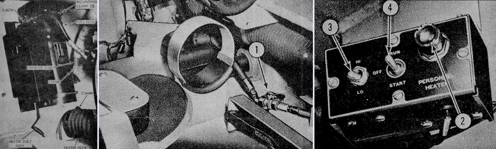
A personnel heater could be emplaced in the hull front to the right of the driver. To start the heater, after the fuel supply valve had been opened (1), the indicator light (2) on the control box was depressed. The lamp lit when depressed, and this ensured electrical continuity. Then the heat selector switch (3) was placed in the HI or LO position, and the heater control switch (4) was held in the START position until the indicator lamp illuminated. This usually took around 90 seconds, but needed longer in extremely cold weather. The heater control switch was then snapped into the RUN position. (Picture from TM 9-2350-230-12.)
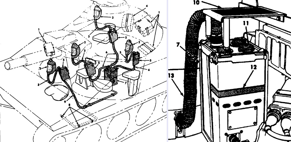
An M8A3 gas-particulate air filter unit provided the crew with protection from toxic gases, biological agent attack, and extremely dusty air. An M2A2 air purifier was installed on the turret floor to the right of the loader's seat, and hoses connected the purifier directly to M25 or M25A1 masks for the three turret crewmen. A fourth hose for the driver's mask was routed through a slip ring. The unit did not protect against carbon monoxide, however, and frostbite to the cheekbone area of the face could result from using the system when the air in the vehicle interior was below 20°F (-7°C).
1. Carrier with protective mask and canister (stowed position). 2. M25 or M25A1 protective mask. 3. Canister to mask hose. 4. Commander's, gunner's and loader's canister-to-air purifier hose stowage bag. 5. Carrier with canister. 6. Canister-to-air purifier hose. 7. Air purifier. 8. Driver's canister-to-air purifier hose stowage clips. 9. Driver's canister-to-air purifier hose. 10. Air purifier foot guard. 11. Airflow control cap (4). 12. Spring clip. 13. Hose, air filter-to-contact ring slip joint. (Picture from TM 9-2350-230-12.)
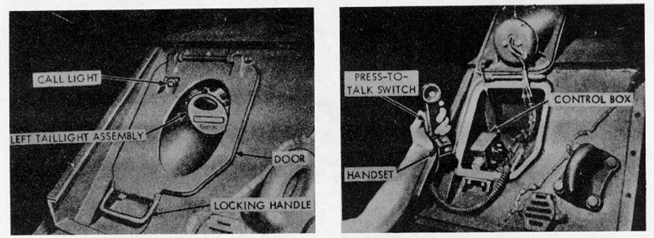
The operation of the infantry phone under the left taillight is shown here. (Picture from TM 9-2350-230-12.)
This earlier machine features the bore evacuator on its 152mm gun-launcher. Note the different shield in front of the .50 caliber machine gun. (Picture courtesy Alison Gerlach.)
The muzzle plug has been removed from this vehicle, and the border of the flotation surfboard can be better discerned lying on the front hull.
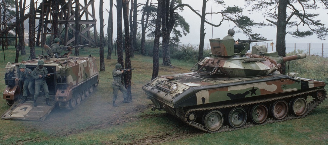
The M551 in this photograph has an AN/VSS-3 white or infrared searchlight mounted to the left of its gun. The tank commander is protected by armored shields that were developed during the Vietnam War. The cupola's split hatch initially provided protection to the sides, but tankers often installed the armored shields from the ACAV M113 to provide more protection. A standardized kit for the Sheridan that provided protection from the front and sides was then developed, and a rear shield was subsequently included. This vehicle is equipped with the later-production smoke grenade launcher installation that lacks the brace running along the bottom of the grenade tubes. This vehicle is also fitted with the later version of the turret bustle stowage rack. The other vehicle in the image is an M113A1 APC. (Picture taken 1 May 1979; available from the Defense Visual Information Center.)
The way that the commander's split hatch integrates with the armor shields when open is better illustrated here.
The surfboard used to prevent swamping and as a front support for the water barrier was folded onto the tank's frontal slope while not in use. Windows were included in the surfboard to allow forward visibility.
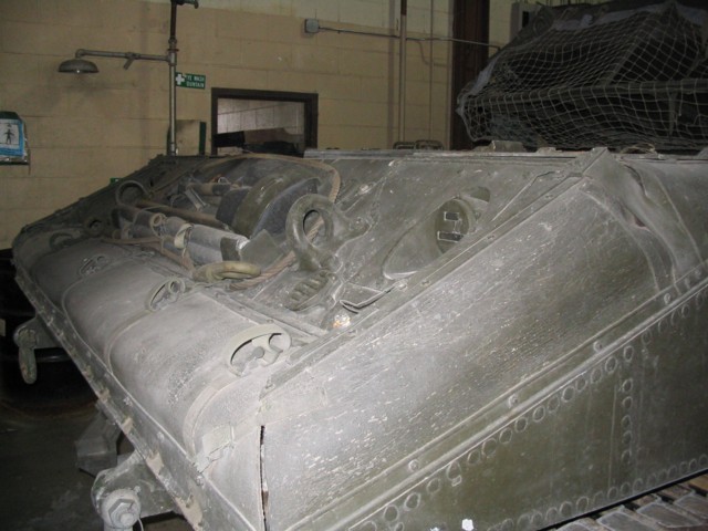
The neoprene-coated nylon flotation barrier was stowed around the edge of the hull under the rounded covers. A pioneer toolkit was stowed on the rear hull.
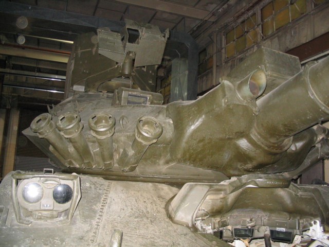
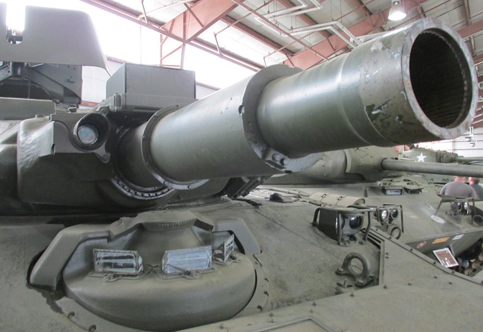
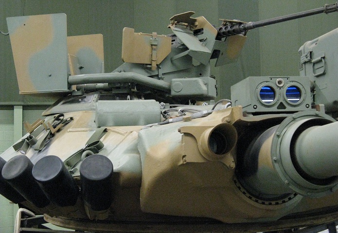
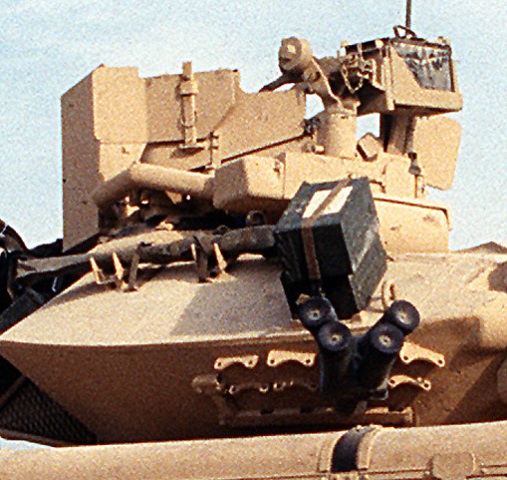
A closer look at the turret front is available here. This vehicle is also equipped with the later-production smoke grenade launchers as well as the TC's ballistic shield kit. The missile transmitter is mounted above the barrel of the gun-launcher, and the gunner's periscope is visible on the turret roof.
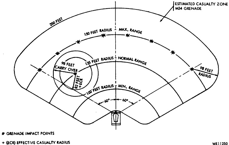
The effective range of the smoke grenades are diagrammed here. (Picture from TM 9-2350-230-12.)
This detached turret is missing its missile transmitter door. When fitted, the door would flip open downward to expose the transmitter optics. The missile tracker is visible to the gun-launcher's right. The laser rangefinder that snakes around the commander's cupola is also obvious when compared with the turret above. This turret is fitted with the later-style smoke grenade launchers and an AN/VVS-3 searchlight.
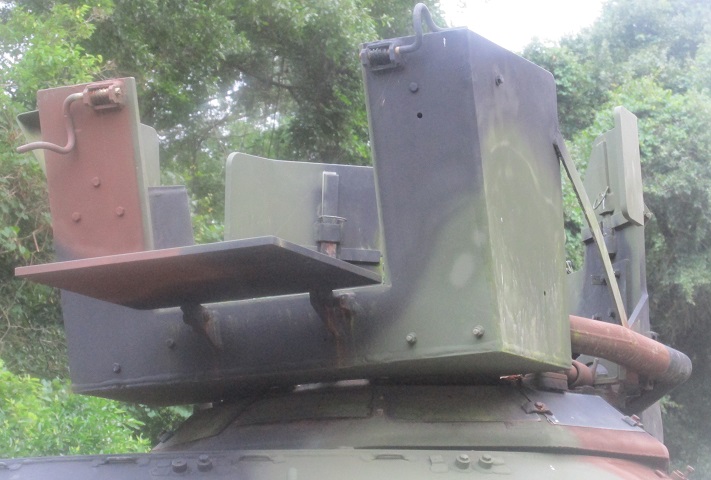
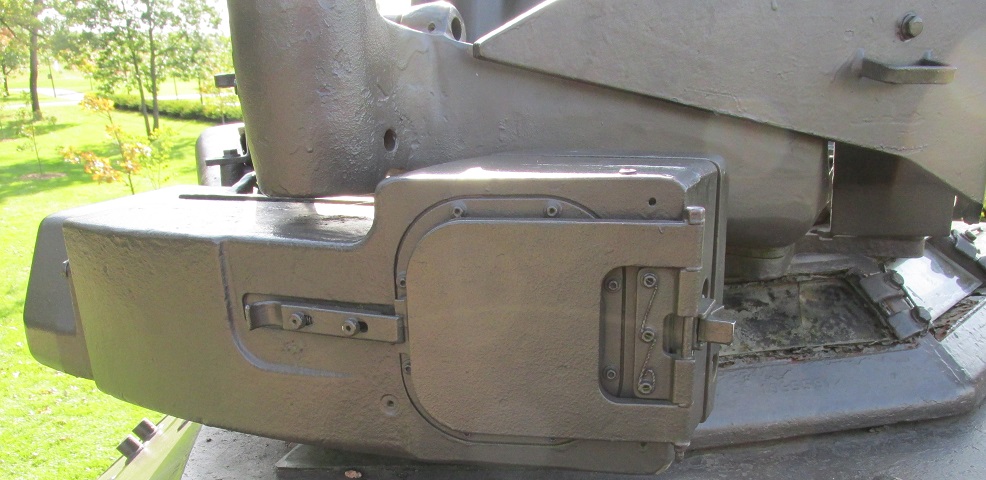
The rear door of the commander's armored shield is open on this machine.
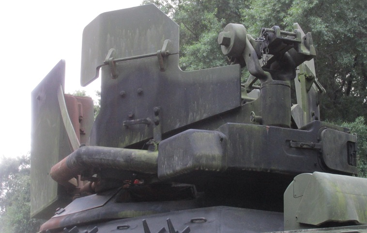
Further details of the laser rangefinder and commander's shield are provided here. The flaps on the front panels are raised. The rangefinder was accurate to within ±10m (±10 yards), and could be used for targets from 200m to 4,000m (220 yards to 4,400 yards) away.
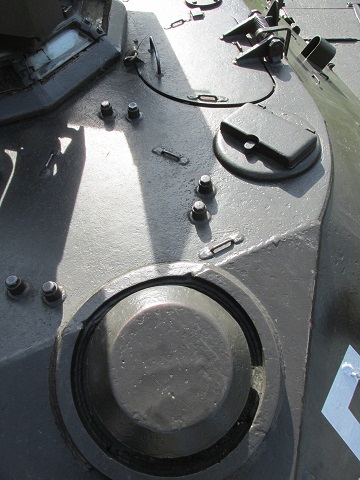
The laser transceiver is highlighted here. The protective cover was hinged on the left so that it opened to the inboard side of the vehicle.
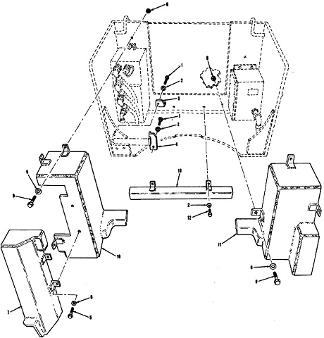
The laser's electronics unit was mounted in the cupola's right rear corner, and the power supply was housed under a similar cover on the opposite side of the cupola. The numbers in the diagram refer to the different fasteners used. (Picture from TM 9-2350-230-25P/2.)
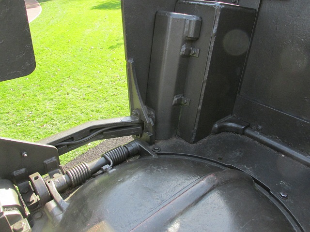
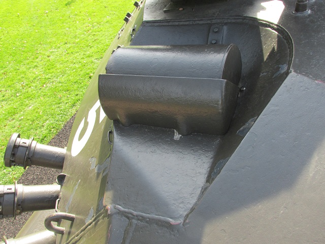
Wiring from the electronics unit can be seen here protected by armor as it makes its way forward to the transceiver.
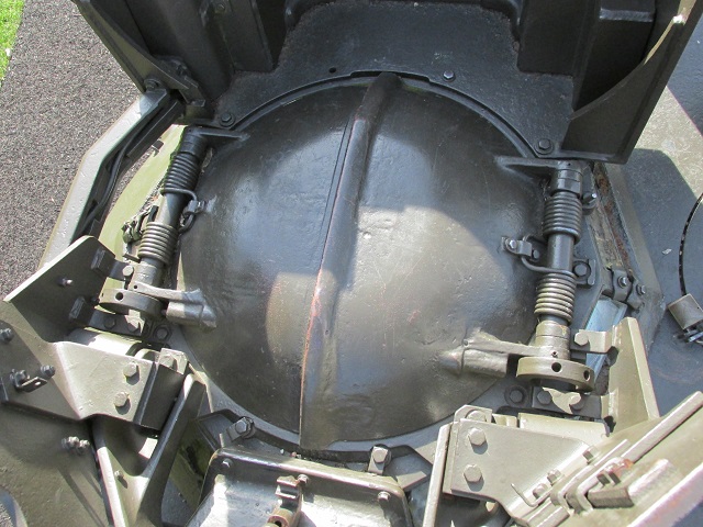
Details of the commander's clamshell door can be gleaned from this image. The electronics unit and power supply are in the rear corners of the cupola armor.
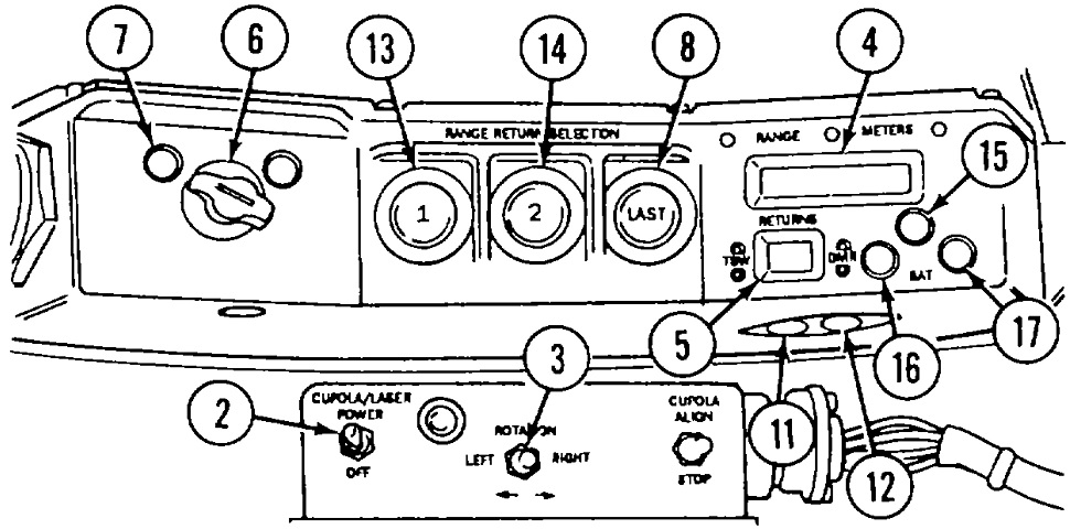
The controls for the commander's laser rangefinder are sketched here. 2. Cupola/laser power switch. 3. Cupola rotation switch. 4. Range readout. 5. Returns readout. 6. Laser mode selector. 7. Test lamp. 8. Range selector last button. 11. TSW test switch. 12. Dimmer switch. 13. Range return selector 1 button. 14. Range return selector 2 button. 15. Malfunction lamp. 16. DR lamp [indicated auxiliary power was being used]. 17 Low auxiliary power supply lamp. (Picture from TM 9-2350-230-10 C2.)
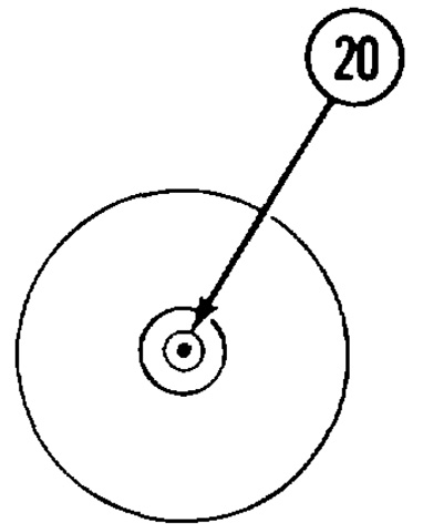
The number 20 is indicating the cross-section for the rangefinder's laser, which was used as the aiming marker for the rangefinder. The circles around the cross-section were 1, 5, and 20 milliradians. The rangefinder could fire 3 times per minute sustained, or 6 times per minute for 2 minutes with 3-minute intervals between each 2-minute ranging period. (Picture from TM 9-2350-230-10 C2.)
The front left corner of the turret roof was home to the ventilator dome as well as the loader's periscope M37. His hatch door is directly behind his periscope. With the introduction of the laser in the M551A1, a rotation stop was added to this periscope to prevent its traverse to the right rear.
The rotating cover for the gunner's periscope M44 is mounted on the outside of the housing; this arrangement would change with the advent of the tank thermal sight. The periscope M44 was typically used for night engagements, with the telescope M127A1 typically used for daylight engagements.
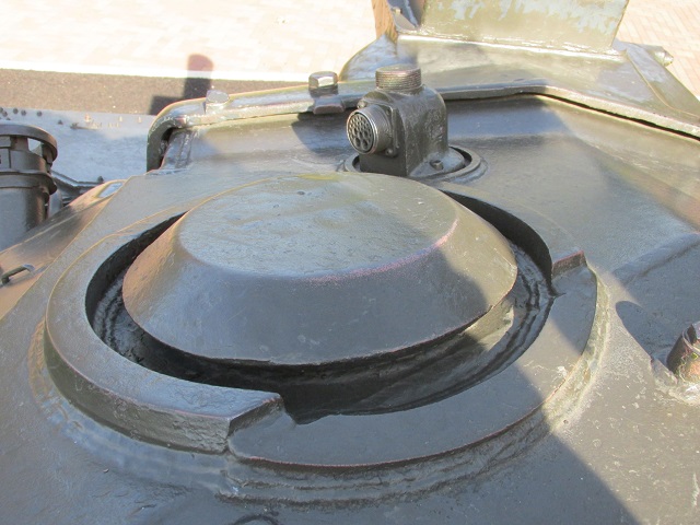
The turret ventilating fan is detailed here, along with the power receptacle for the searchlight. The plug for the searchlight would normally be covered by a cap, which could be threaded onto the top of the receptacle when the plug was in use.
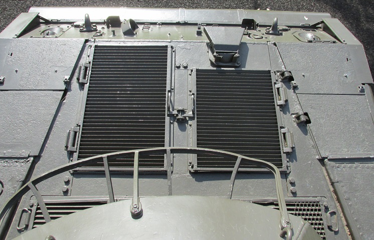
The engine deck is shown here, looking down from the turret. The left-side engine compartment exhaust grille is shorter thanks to the placement of the engine exhaust. Note the hinge above the left-side taillight housing, which allowed access to the intercom set beneath.
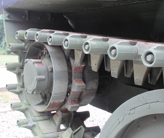
The drive sprocket is the focus of this image.
The original XM176 smoke grenade launchers were replaced by M243 grenade launchers. (Picture from TM 9-2350-230-10 C2.)
The flotation barrier and surfboard are erected in this illustration. When static in the water, there was -2.5" (-6.4cm) freeboard to the top of the hull in front, and +2.5" (+6.4cm) at the rear. When moving in the water, the vehicle leveled out a bit, with -.5" (-1.3cm) freeboard to the front and +.5" (+1.3cm) at the rear. 1. Flotation surfboard. 2. Flotation barrier. 3. Rear bilge pump outlet. 4. Front bilge pump outlet. (Picture from TM 9-2350-230-10 C2.)
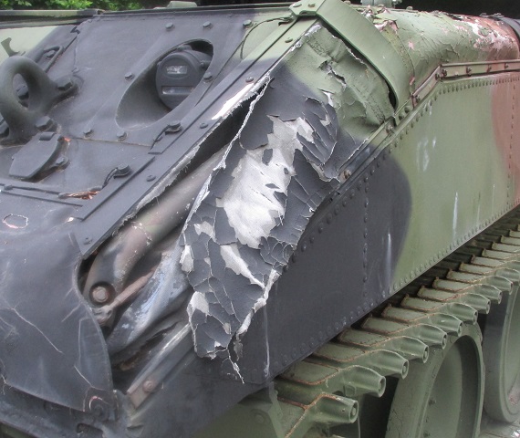
The cover for the flotation barrier on this machine has degraded to the point that a view beneath is provided. The barrier material and support struts are visible.
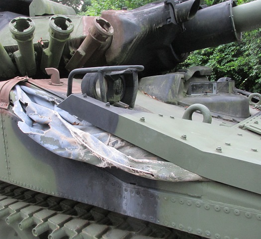
The flotation barrier on the front right corner is visible as well.
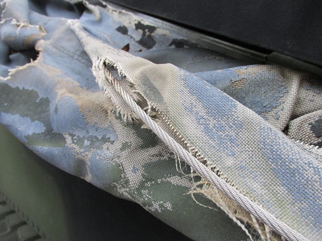
Details of the material, supporting lines, and camouflage applied can be seen in this image.
The gunner's station in an M551A1(TTS) is sketched here. The laser rangefinder remained attached to the commander's cupola, so he continued to operate the rangefinder. (Picture from TM 9-2350-230-10 C2.)
The conventional and missile reticle pictures for the TTS are seen above. (Picture from TM 9-2350-230-10 C2.)
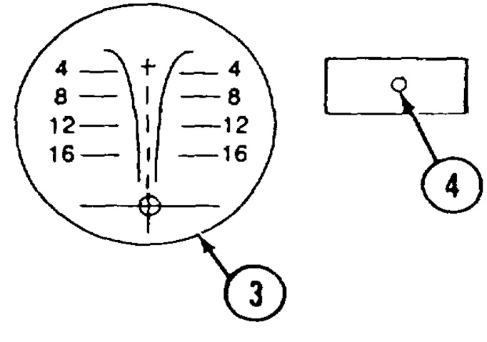
The daylight (3) and unity (4) reticles for the TTS are drawn in these pictures. (Picture from TM 9-2350-230-10 C2.)
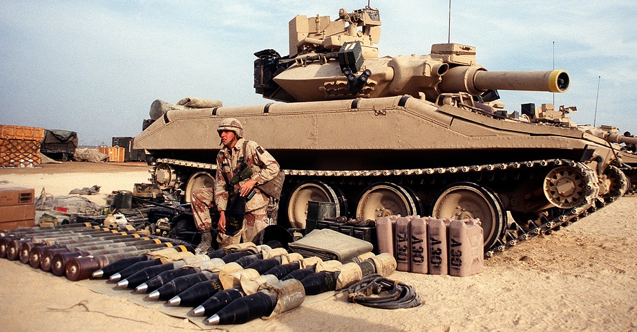
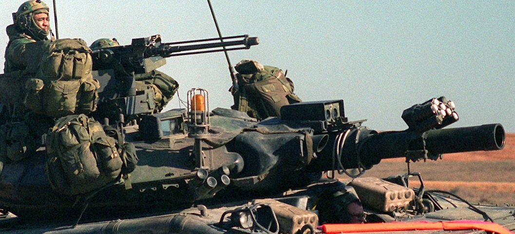
The gun-launcher on this M551A1(TTS) lacks a bore evacuator, so this vehicle is equipped with the closed-breech scavenging system. The commander's weapon station has been fitted with armor protection, and additional machine gun ammunition could be stowed around the circumference of the turret. The laser rangefinder transceiver is visible just above the spare ammunition box, and the cable cover runs around the right side of the cupola. M243 smoke grenade launchers are mounted over the brackets for the older XM176 grenade launchers. One-hundred fifty-two millimeter ammunition is stored with protective bags around the combustible cartridge case; the bag is removed before firing. (Picture taken 1 Dec 1990 by Spc. Henry; available from the Defense Visual Information Center.)
Zooming in on the TTS periscope, it is possible to see the difference in construction of the periscope guard versus the M44 periscopes on the above machines. (Picture taken 19 Mar 1996 by Spc. Henry; available from the Defense Visual Information Center.)
The cover for the tank thermal sight is rotated open on this machine, and the missile transmitter door is open as well. The protective cover for the TTS retracts into the periscope housing instead of around it, and has a straight edge as opposed to the two notches on the cover of the periscope M44. This crew was supporting a training rotation by the 82nd Airborne Division. A blank adapter is fitted to the commander's machine gun, and pyrotechnics are strapped to the gun-launcher barrel to simulate its discharge. (Picture taken 1 Dec 1990 by Raymond Barnard; available from the National Archives.)
