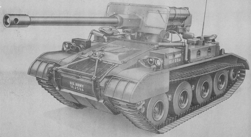
90mm Self-propelled Gun M56.
The driver's window in the blast shield can be seen from this angle. The gun travel lock is secured in its stowed position, and the engine's exhaust pipes snake up and over each fender. Seats for the commander and loader are mounted on top of the radio and right fender stowage box, respectively. (Picture from TM 9-2350-213-10 C9 Operation 90-mm Full Tracked Self-propelled Gun M56.)
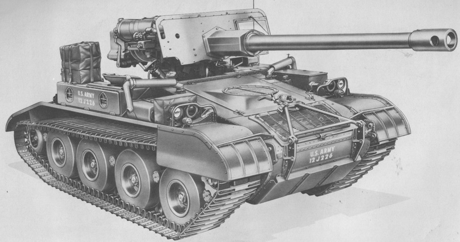
The vehicle is shown from the opposite side, with the aperture for the gunner's telescope visible in the blast shield. (Picture from TM 9-2350-213-20 Organizational Maintenance 90-mm Full Tracked Self-propelled Gun M56.)
This vehicle is fully stowed, showing the location of the towing cable looped around the rear, fire extinguisher on the right fender behind the stowage box, and M1945 canvas packs strapped to the right-side stowage box. (Picture from TM 9-2350-213-10 Operation 90-mm Full Tracked Self-propelled Gun M56.)
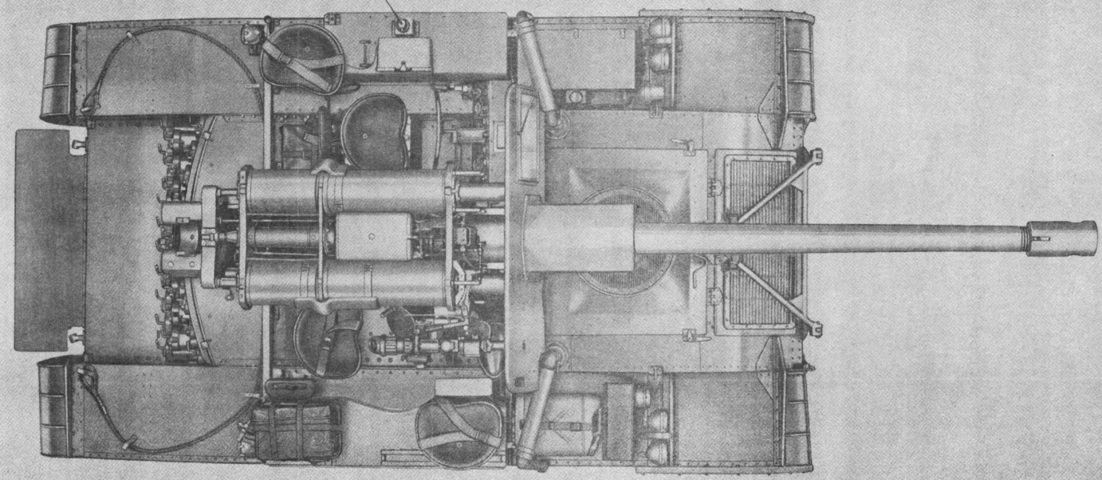
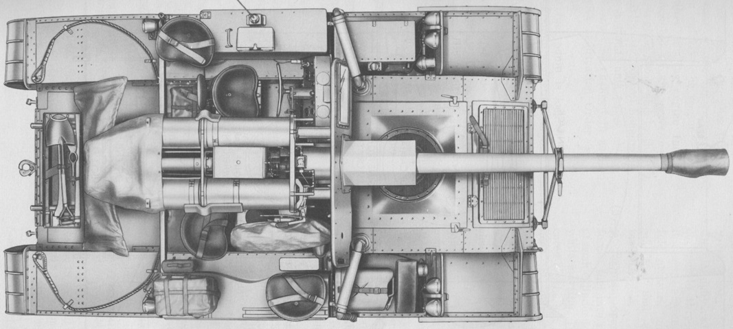
The crew positions are more easily seen from above, with the gunner just to the ordnance's right, the driver on the gun's opposite side, and the commander and loader on the fenders. The extra real estate given by the folding loader's platform at the vehicle's rear is obvious. Note that the 90mm ammunition rack arced across the rear of the hull. (Picture from TM 9-2350-213-10 C9 Operation 90-mm Full Tracked Self-propelled Gun M56.)
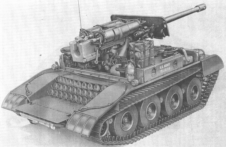
Covers have been installed over the ordnance and ammunition, and the loader's platform has been folded forward, revealing pioneer tool stowage on its underside. (Picture from TM 9-2350-213-20 Organizational Maintenance 90-mm Full Tracked Self-propelled Gun M56.)
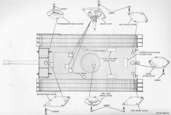
The various covers and plugs on the hull bottom are labeled here. (Picture from TM 9-2350-213-20 Organizational Maintenance 90-mm Full Tracked Self-propelled Gun M56.)
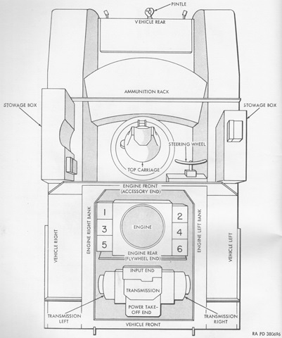
This diagram illustrates the orientation of the engine and transmission as well as the cylinder numbering convention. (Picture from TM 9-2350-213-20 Organizational Maintenance 90-mm Full Tracked Self-propelled Gun M56.)
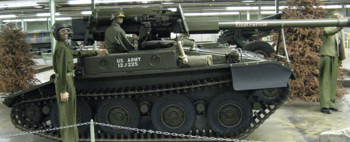
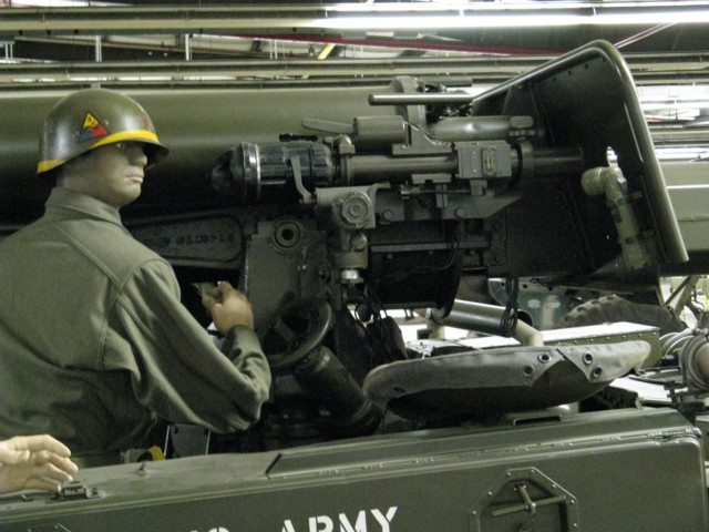
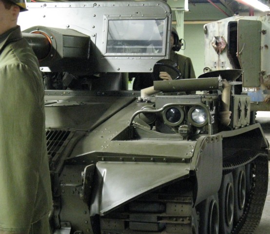
The very basic design of the M56 can be seen in this picture. Creature comforts, and even weather protection, were nonexistent. The mannequin in the vehicle is sitting in the gunner's position, and the seat for the loader is visible on the fender stowage box just in front of the gunner. The right-hand exhaust pipe for the engine can be seen exiting the front slope directly below the blast shield.
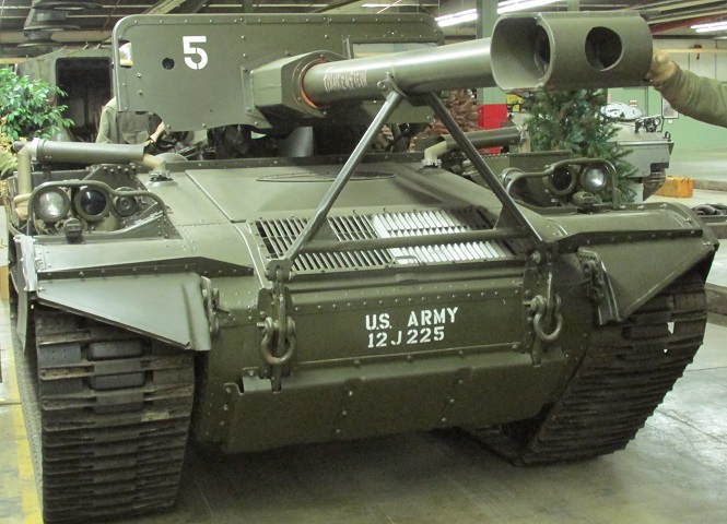
The circular air intake and rectangular air exhaust grilles can easily be seen on the front of the hull. The grille on the very front of the hull covers the transmission, and the engine access door, which would normally have locking handles on its forward corners, is directly behind. The engine exhaust pipes exit to each side of the rear of the engine compartment, and discharge over the fenders. The gun would normally end in a cylindrical blast deflector counterweight instead of the T-shaped muzzle brake present on this machine. The arrangement of the gun travel lock can also be seen.
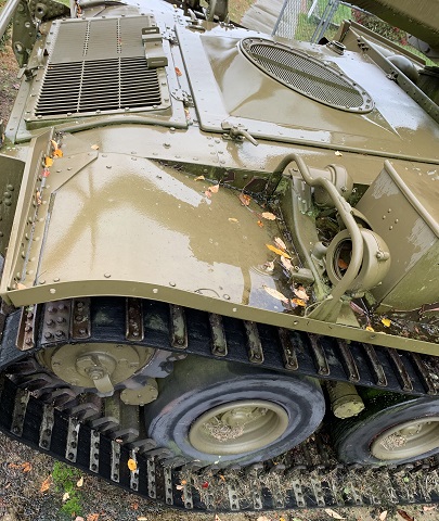
The grilles on the hull can be better seen in this image, and the port for the missing right-hand exhaust pipe is visible on the opposite side of the engine cover.
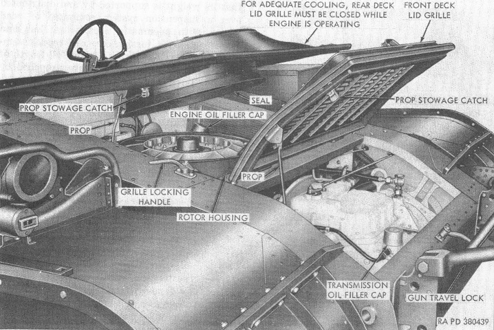
The grilles have been opened in this illustration, providing a view into the engine compartment. (Picture from TM 9-2350-213-10 Operation 90-mm Full Tracked Self-propelled Gun M56.)
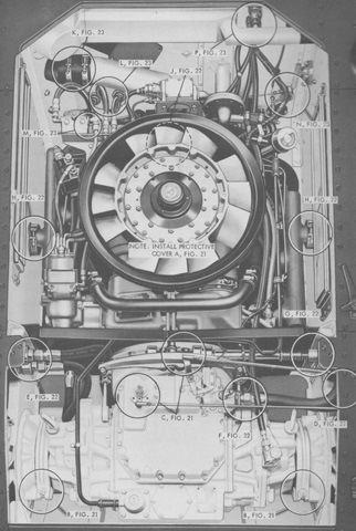
The engine and transmission are shown installed in the vehicle with various disconnect points highlighted. (Picture from TM 9-2350-213-20 Organizational Maintenance 90-mm Full Tracked Self-propelled Gun M56.)
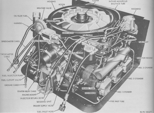
The engine is seen here from the front. Bore and stroke were 4.625" (11.75cm) and 4.000" (10.16cm), respectively, for a displacement of 402in³ (6,590cm³). It was 34.53" (87.71cm) long, 28.53 (72.47cm) high, 37.50" (95.25cm) wide, and weighed 746lb (338kg) dry with accessories. Its compression ratio was 6.9:1, and governed speed was 3,000rpm. (Picture from TM 9-2350-213-20 Organizational Maintenance 90-mm Full Tracked Self-propelled Gun M56.)
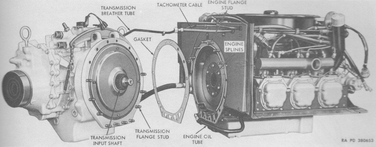
The separated transmission and engine are illustrated. The CD-150-4 was a torque converter, lockup clutch, planetary-geared transmission with hydraulically-applied friction elements that controlled the gear ratios. Overall usable gear ratios were 13.95:1 for low, 6.08:1 for high, and 13.95:1 for reverse. The final reduction ratio was 4.8:1. The transmission weighed 550lb (250kg) and contained ~15 quarts (~14L) of oil. (Picture from TM 9-2350-213-20 Organizational Maintenance 90-mm Full Tracked Self-propelled Gun M56.)
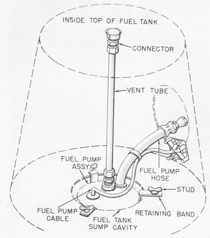
The top carriage for the 90mm gun actually sat atop the vehicle's fuel tank, which is diagrammed in this sketch. (Picture from TM 9-2350-213-20 Organizational Maintenance 90-mm Full Tracked Self-propelled Gun M56.)
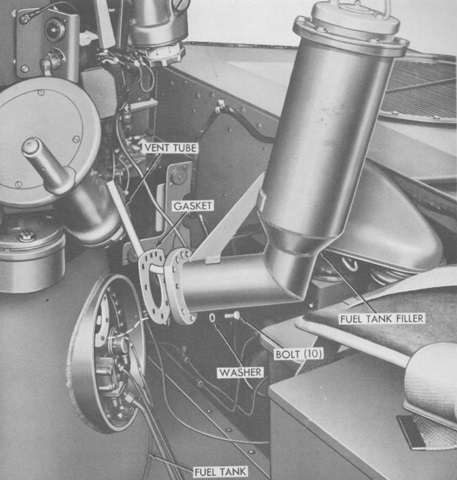
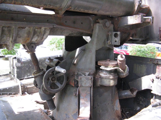
The fuel filler is shown here in the process of installation. The gunner's traverse handwheel and other controls can be seen at the upper left. (Picture from TM 9-2350-213-20 Organizational Maintenance 90-mm Full Tracked Self-propelled Gun M56.)
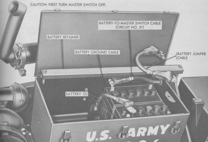
The battery box was located on the left fender just ahead of the driver's instrument panel. Two 12-volt batteries were connected in series to create a 24-volt system. In order to access the batteries, it was necessary to loosen the exhaust pipe clamps and swing the outer exhaust pipe out of the way. (Picture from TM 9-2350-213-20 Organizational Maintenance 90-mm Full Tracked Self-propelled Gun M56.)
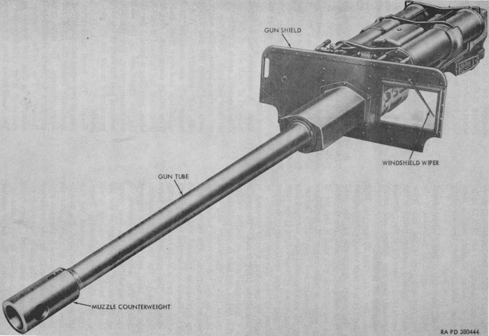
The gun tube was supported by cast-steel rails attached to each side of the top carriage. These rails each carried a bronze guide to support the gun during recoil and counterrecoil. The gun and counterweight weighed 2,440lb (1,110kg), with the tube comprising 1,473lb (668.2kg) of that. The tube's estimated accuracy life was 700 equivalent full charge rounds. (Picture from TM 9-2350-213-10 C9 Operation 90-mm Full Tracked Self-propelled Gun M56.)
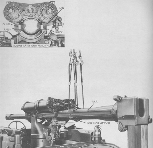
The rails and guides are visible here with the gun in the process of being removed. (Picture from TM 9-2350-213-20 Organizational Maintenance 90-mm Full Tracked Self-propelled Gun M56.)
A closer view of the gunner's position is provided here. The gunner used a telescope T186 for aiming the gun, and his right hand is resting on the traverse handwheel.
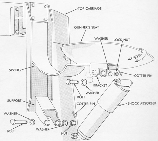
Perhaps in deference to the power of the ordnance versus the weight of the vehicle, the gunner was provided with a sprung seat complete with a shock absorber. (Picture from TM 9-2350-213-20 Organizational Maintenance 90-mm Full Tracked Self-propelled Gun M56.)
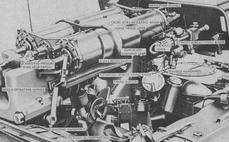
Gun and telescope mount controls and instruments are labeled in this picture. The gun mount weighed 1,868lb (847.3kg) including fluid. (Picture from FM 23-43 90-mm, Full-tracked, Self-propelled Gun, M56.)
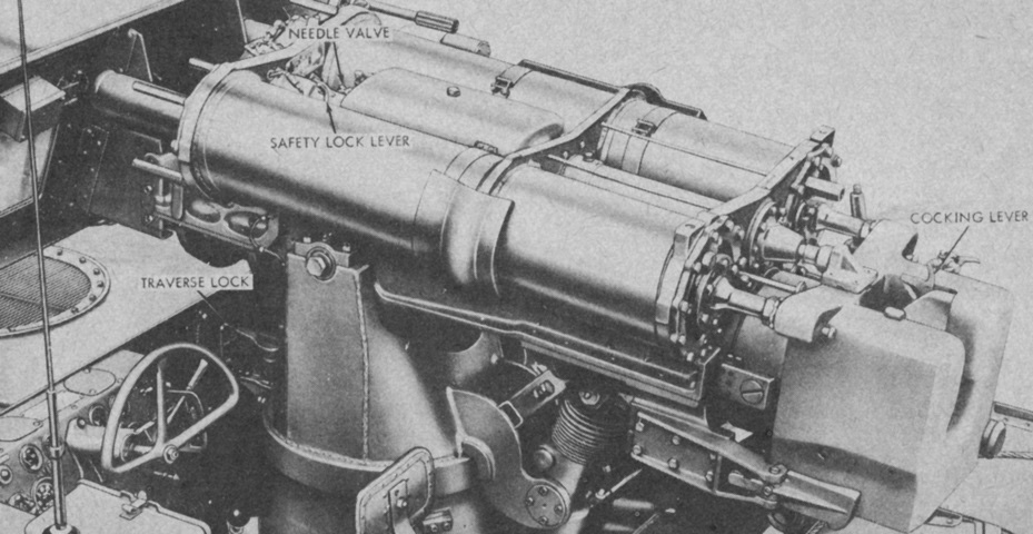
The opposite side of the gun mount is seen. (Picture from FM 23-43 90-mm, Full-tracked, Self-propelled Gun, M56.)
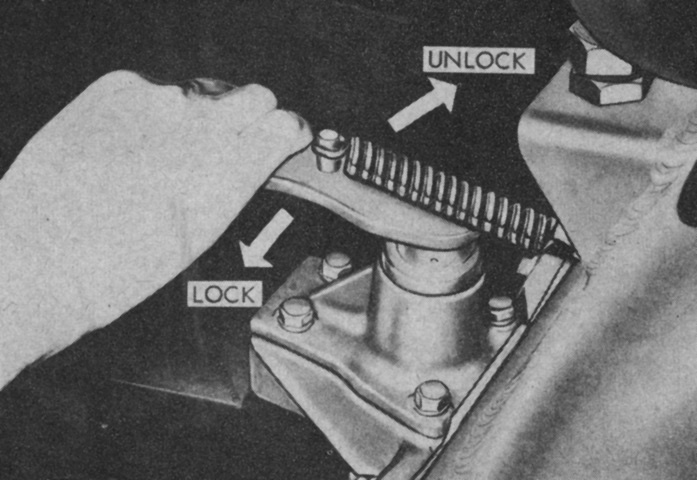
In addition to the gun travel lock mounted on the front hull, the gun mount featured a traverse lock. The traverse lock was used when the vehicle was moving in a tactical situation with the gun not secured in the travel lock. The traverse lock helped reduce vibration-induced wear to the gun mount. (Picture from FM 23-43 90-mm, Full-tracked, Self-propelled Gun, M56.)
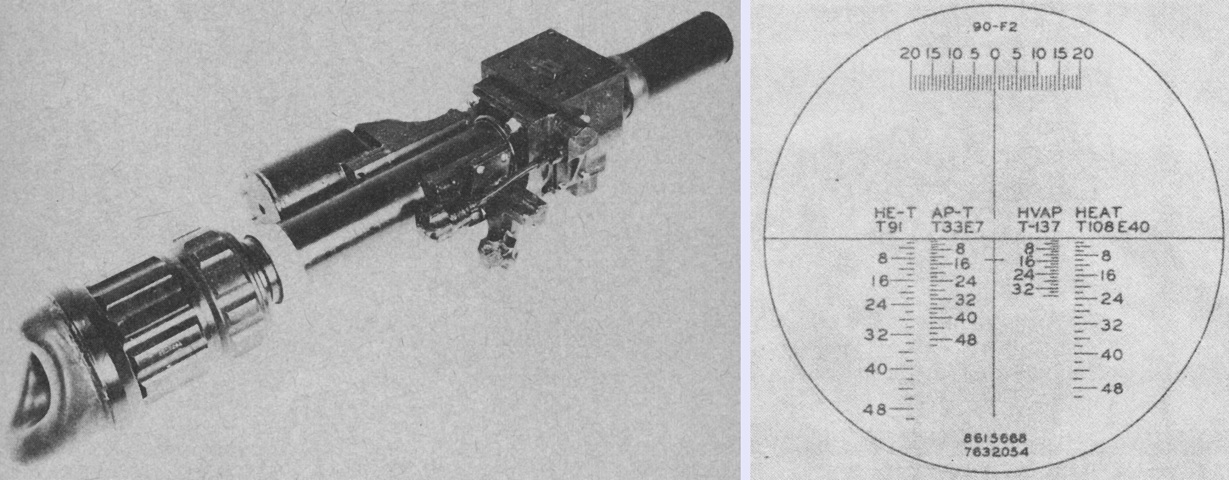
The telescope M91D was a variable 4x to 8x instrument with a cross-level adjustment to account for cant. The large adjustment ring just in front of the eyeshield changed the magnification power, while the thinner adjustment ring in front of this was the diopter adjustment. As seen on the right, its reticle had four range scales graduated in hundreds of yards for, left to right, high-explosive tracer, armor-piercing tracer, hypervelocity armor-piercing, and high explosive antitank. The short horizontal line on the vertical crosshair was the battlesight index used for surprise or fleeing targets. First-round hits were probable at ranges up to those indicated on the range scales at the level of the battlesight index. At the top of the reticle was a lead scale graduated in 1-mil intervals from 0 to 20 mils to the right and left. The horizontal and vertical crosshairs were moved by the superelevation and lead knobs on the underside of the forward portion of the telescope. The superelevation knob faces to the rear and is parallel with the telescope tube, while the lead knob is angled away from the telescope. The gunner would adjust the horizontal crosshair to the appropriate estimated range for the ammunition being used, and the vertical crosshair to the appropriate lead on the mil scale if the target was in motion. The crosshair was then centered on the target to fire the gun. (Picture from FM 23-43 90-mm, Full-tracked, Self-propelled Gun, M56 and TM 9-2350-213-10 C9 Operation 90-mm Full Tracked Self-propelled Gun M56.)
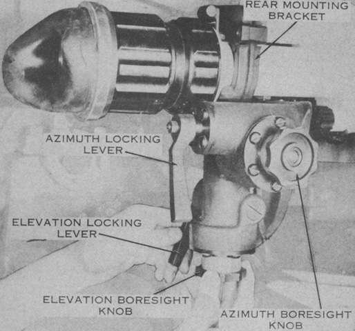
The M91D is installed in the telescope mount M87A1, and the mount boresighting controls are labeled. The horizontal cylindrical cross-level vial can be seen adjacent to the rear mounting bracket above the diopter adjustment ring; the cross-level knob that provided for cant adjustment was on the opposite side. (Picture from FM 23-43 90-mm, Full-tracked, Self-propelled Gun, M56.)
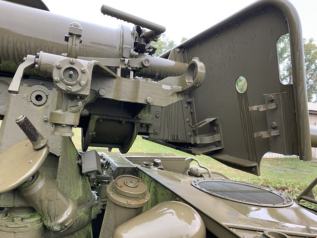
The sight mount and aperture in the blast shield are more easily seen on this example with the sight telescope and flashlight absent. The rearward-facing ninety-degree handle above the telescope mount was the hydraulic hand pressure pump for pressurizing the recoil system if it ran low.
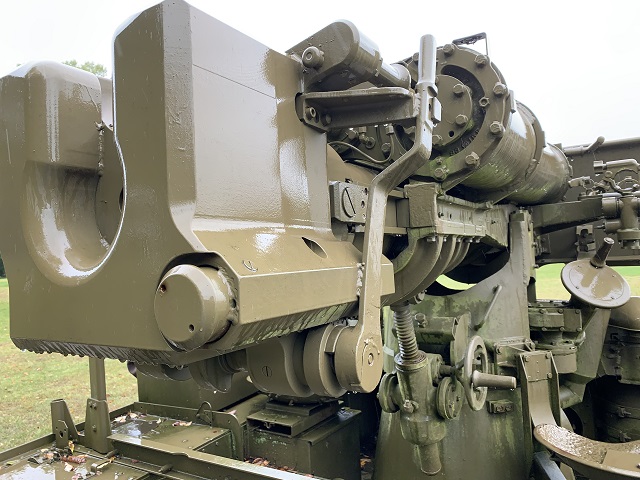
The breech of the 90mm gun is shown here. The operating handle and elevation and recoil mechanisms can all be seen. The breech was opened manually for the first round, and thereafter counterrecoil action opened the breech, extracted the spent case, cocked the percussion mechanism, and locked the breech open.
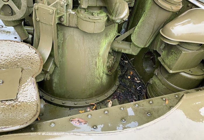
An engine air cleaner occupied the front right corner of the crew compartment. The position of the gunner's seat mount on the gun mount can also be seen.
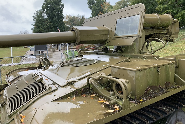
The gunner's seat is present on this machine, and the gun mount's attachment to the fuel tank can be seen.
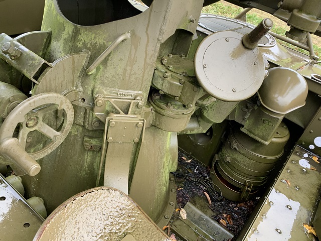
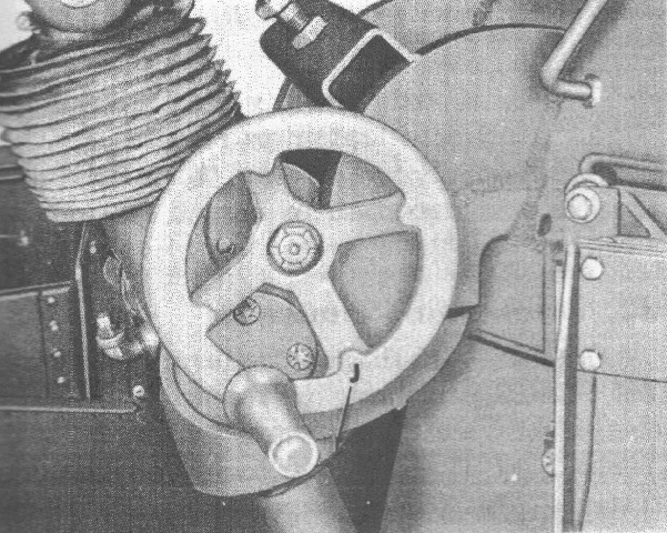
The traverse handwheel was to the gunner's front, and the elevation handwheel was directly to his left. One rotation of the traverse handwheel moved the gun through an arc of 16.21 mils. The firing button is at the end of the traverse handwheel handle.
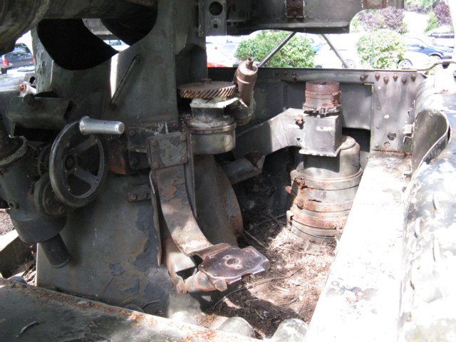
The traverse handwheel has disappeared from this vehicle, providing a glimpse of the gearing used. The elevation handwheel is still present to the rear of the gun mount, although the accordion-like neoprene dust boot that normally protected the elevating screw is gone. A rotation of the elevating handwheel moved the gun through an arc of 3.75 mils.
The protective boot for the elevation screw is present in this picture. (Picture from TM 9-2350-213-10 Operation 90-mm Full Tracked Self-propelled Gun M56.)
The top of the gun mount M88 is highlighted here. (Picture from TM 9-2350-213-10 Operation 90-mm Full Tracked Self-propelled Gun M56.)
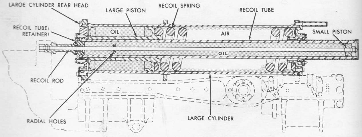
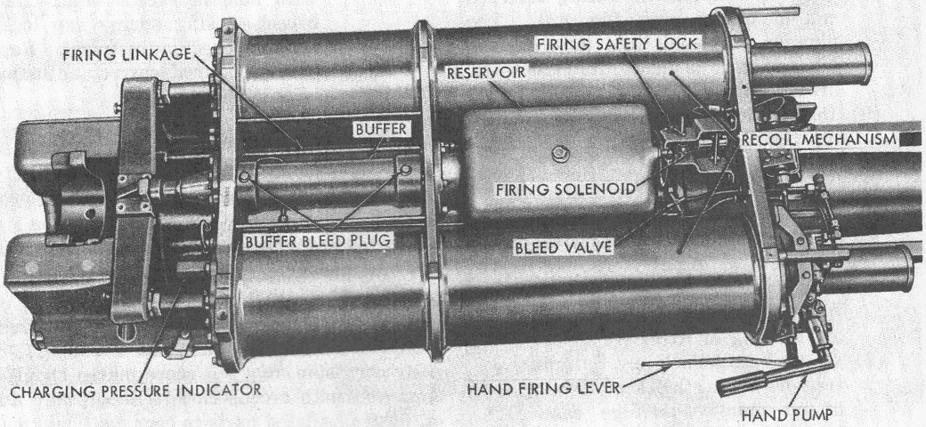
The hydraulic recoil system consisted of two recoil tubes concentrically mounted in the left and right large recoil cylinders. The recoil rod in each tube was attached to the breech ring and, upon firing, pulled the small piston back through the recoil tube. This forced hydraulic fluid out through the tube's orifices and holes in the large cylinder piston, pushing the large pistons into the recoil spring. The recoil action was controlled by the radial holes in the recoil tube and large piston as well as the compound taper on the outside diameter of the recoil tube. The recoil spring then returned the large piston to its original position, returning the hydraulic fluid to the recoil tube and pushing the small cylinder forward and returning the gun to battery. Counterrecoil force was mitigated by a buffer piston which was pulled to the rear upon firing and forced forward through an oil-filled cylinder during counterrecoil. (Picture from TM 9-2350-213-20 Organizational Maintenance 90-mm Full Tracked Self-propelled Gun M56.)
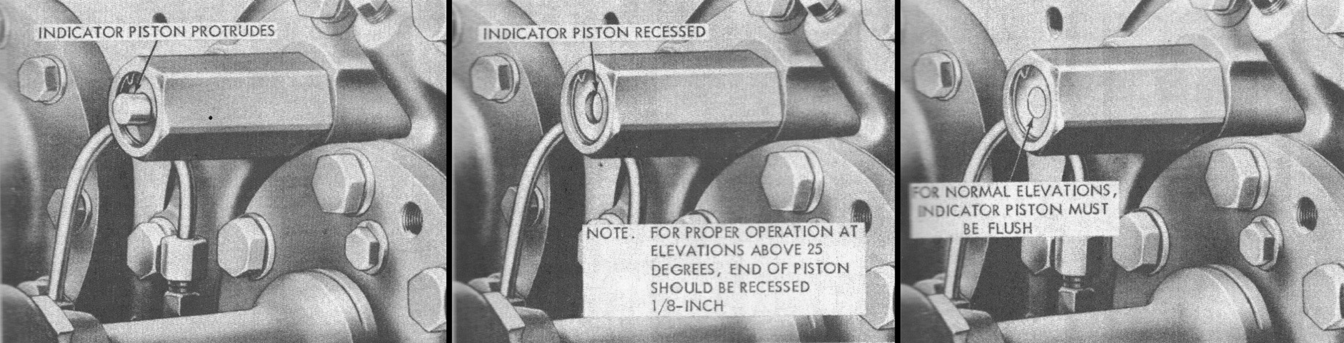
The charging pressure indicator at the right rear of the gun mount showed the status of the recoil system. If the indicator piston protruded from its housing, too little hydraulic oil pressure existed to counter the force of the gun's recoil. If the indicator piston was recessed, the hydraulic pressure would prevent the gun from recoiling properly. The just-right pressure would have the piston flush with its housing (except for elevations as noted in the image). The recoil system had a capacity of 8 gallons (30L) of oil including the reservoir. (Pictures from TM 9-2350-213-10 Operation 90-mm Full Tracked Self-propelled Gun M56.)
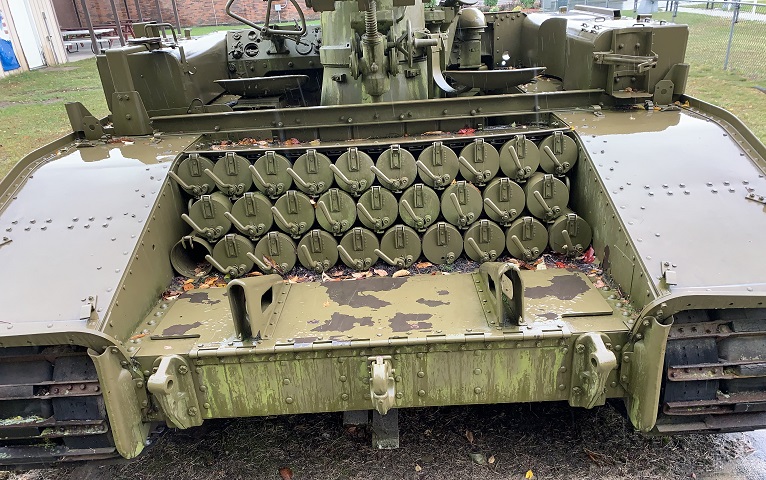
Ammunition stowage for the 90mm gun was provided in the rear of the vehicle, and here the loader's platform is folded forward on top of the hull rear.
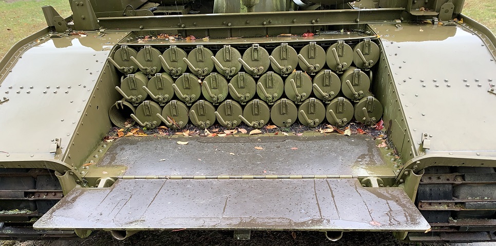
The loader's platform is unfolded in this image.
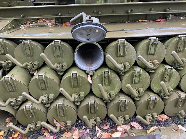
The 90mm ammunition was held in place and protected from the environment by spring-loaded caps.
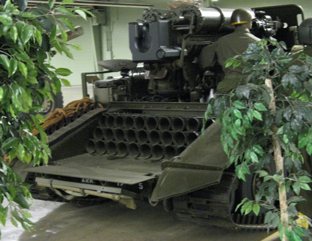
Pioneer tools were stowed on the underside of the loader's platform. Note that this machine is missing the caps for the 90mm ammunition stowage tubes.
The driver's window in the blast shield can clearly be seen in this image. The small hole centered above the window was for a windshield wiper, which is missing on this machine. The vehicle commander's seat is also present on top of the radio box on the left-hand fender, and the engine's left-hand exhaust pipe is also visible.
The driver's side is shown here, with a stowage box on the front fender behind the light cluster.
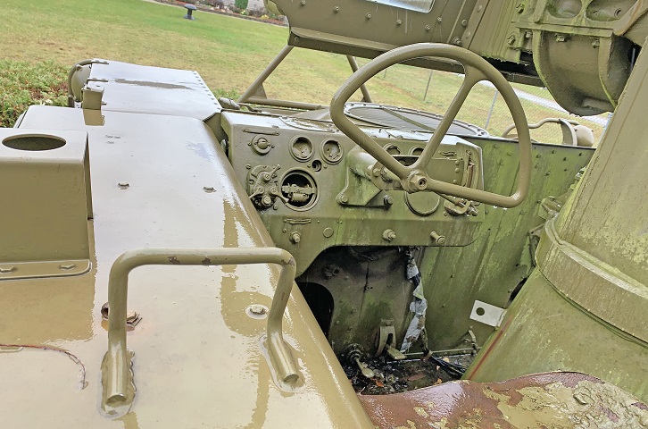
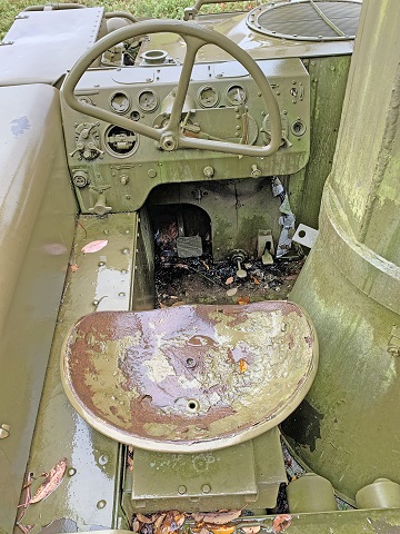
The driver sat in the front left of the hull. The gauges are missing from his instrument panel, but the lighting switches and transmission selector remain behind the steering wheel. An antenna guard for the radio can be seen at the left edge of the frame, and a grab handle for the commander is in the foreground. The driver's seat is at the bottom right.
The driver was confined by the gun mount on the right and the fender to his left. His foot pedals included the large square brake pedal located in the recess to his front, the small foot throttle to its right, and the foot switch for the hull drainage valves to the right of the foot throttle.
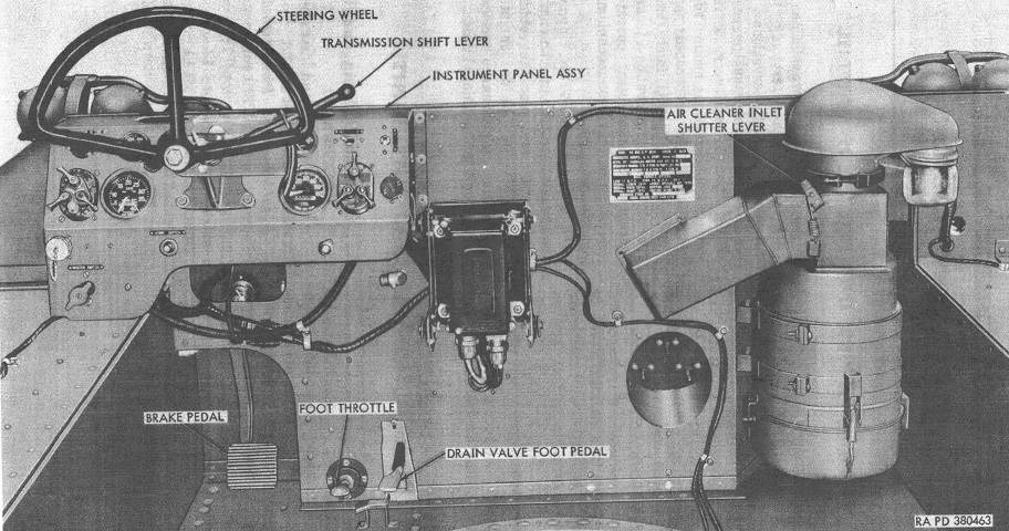
A broad view of the driver's position is provided here with the gun mount absent. (Picture from TM 9-2350-213-10 Operation 90-mm Full Tracked Self-propelled Gun M56.)
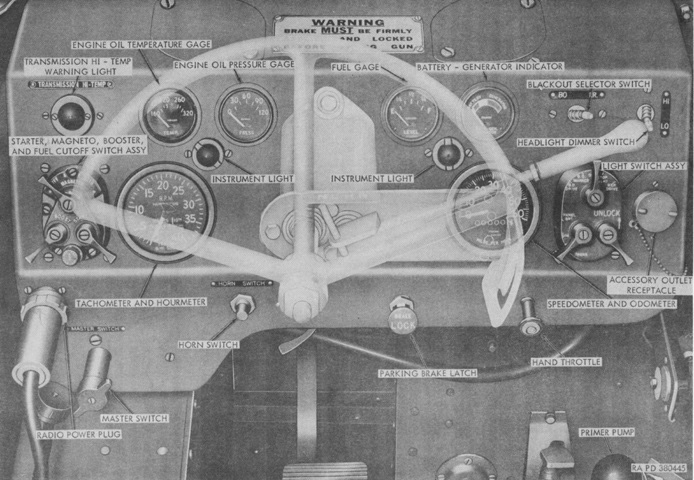
The driver's controls are labeled in this image. (Picture from TM 9-2350-213-10 Operation 90-mm Full Tracked Self-propelled Gun M56.)
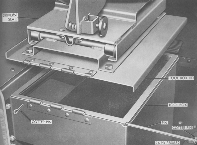
The driver's seat was mounted to the lid of a toolbox, which is shown here being removed or installed. (Picture from TM 9-2350-213-20 Organizational Maintenance 90-mm Full Tracked Self-propelled Gun M56.)
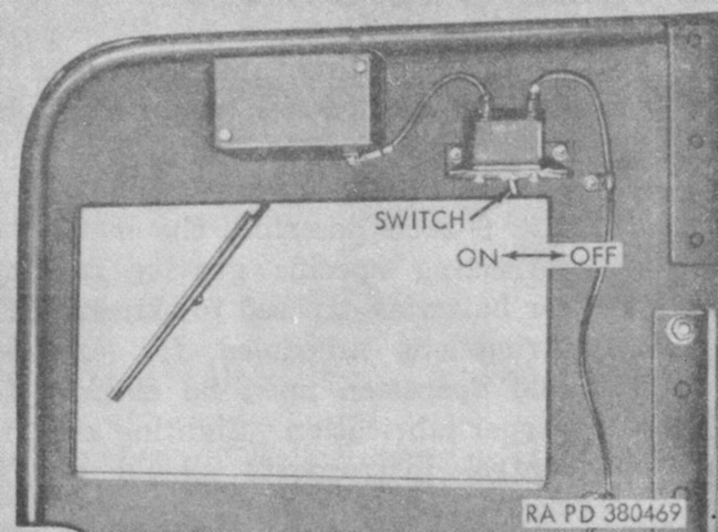
Operation of the control switch for the driver's windshield wiper is shown here. (Picture from TM 9-2350-213-10 C9 Operation 90-mm Full Tracked Self-propelled Gun M56.)
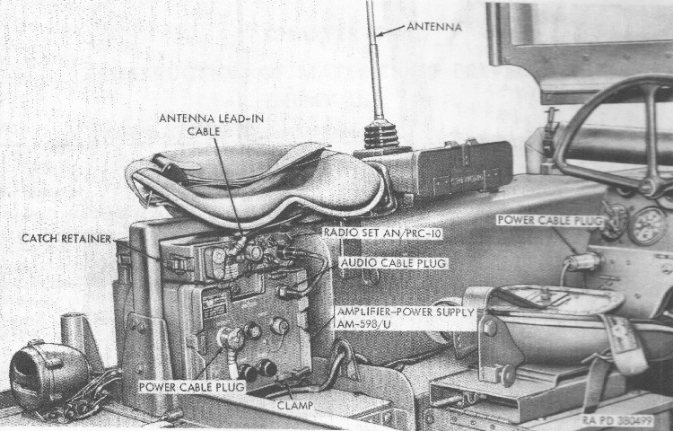
The radio set and commander's seat are shown here. Besides the AN/PRC-10 shown, the AN/PRC-8 or -9 could also be installed in mounting MT-759/PRC, which was made up of four shock mounts in a steel frame. The amplifier power supply AM-589/U adapted the radio sets for use in vehicles, and had an audio amplifier to enable use of a speaker. (Picture from TM 9-2350-213-10 Operation 90-mm Full Tracked Self-propelled Gun M56.)
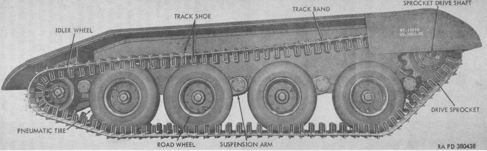
The suspension is labeled in this picture. The front and rear suspension arms had extensions to accommodate the sprocket carrier and idler wheel, respectively. (Picture from TM 9-2350-213-10 C9 Operation 90-mm Full Tracked Self-propelled Gun M56.)
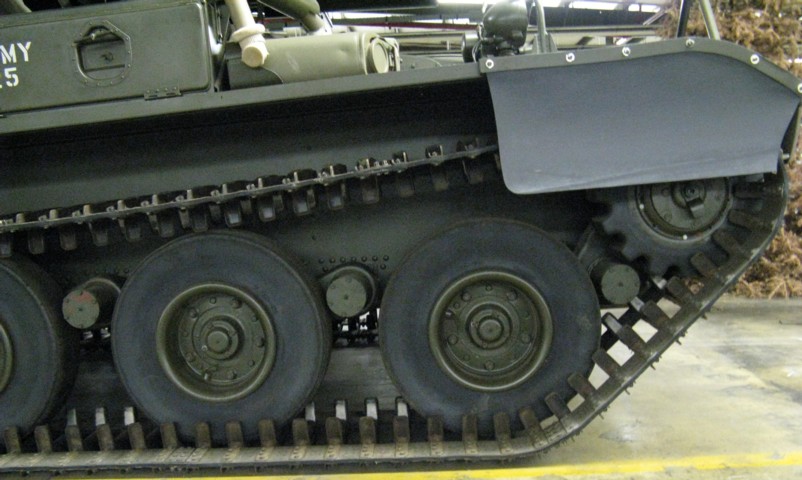
The run-flat pneumatic tires, rubber drive sprocket ring, and band-type tracks were unusual features of the M56.
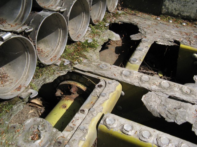
The rusted-through rear platform on this vehicle allows a glimpse of the location of torsion tube-over-bar suspension of the last road wheel station.
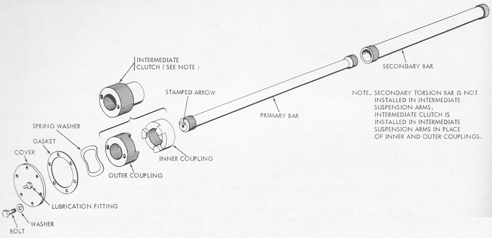
The primary and secondary torsion bars present at the front and rear road wheel stations are shown in this exploded view. The primary torsion bars carried the entire load under normal conditions, but the secondary bars assisted when heavy or shock loads were encountered. The center two road wheels were suspended only by the primary bars as noted, and the intermediate clutch was instead installed on the end of the primary bar at these stations. (Picture from TM 9-2350-213-20 Organizational Maintenance 90-mm Full Tracked Self-propelled Gun M56.)
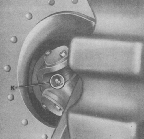
A universal joint was present in the drive shaft that connected to the sprocket on each side. The sprockets were given a degree of movement due to the suspension arm that also connected to the front road wheel. (Picture from TM 9-2350-213-10 C9 Operation 90-mm Full Tracked Self-propelled Gun M56.)
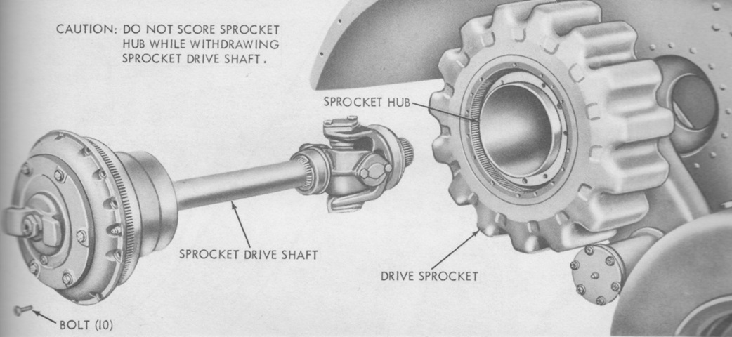
The sprocket drive shaft and universal joint are shown removed from the vehicle. (Picture from TM 9-2350-213-20 Organizational Maintenance 90-mm Full Tracked Self-propelled Gun M56.)
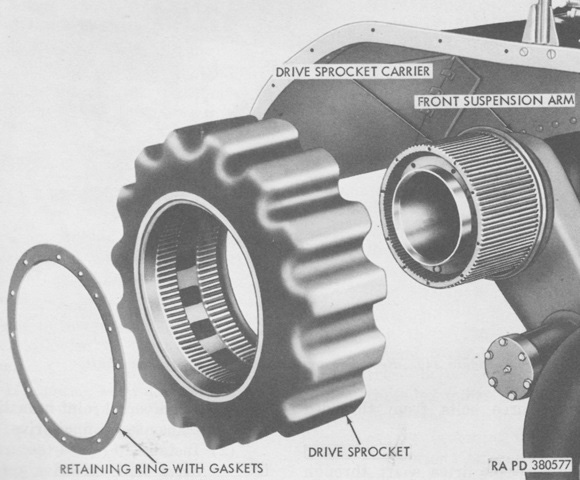
The rubber drive sprocket had a pitch diameter of 19.09" (48.49cm). (Picture from TM 9-2350-213-20 Organizational Maintenance 90-mm Full Tracked Self-propelled Gun M56.)
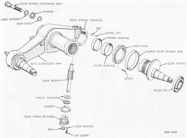
An exploded view of the rear suspension arm and idler spindle is provided here. To adjust track tension, the idler spindle retaining bolt was loosened, then the spindle adjusting wormshaft was turned clockwise to tighten the track or counterclockwise to loosen it. (Picture from TM 9-2350-213-10 C9 Operation 90-mm Full Tracked Self-propelled Gun M56.)
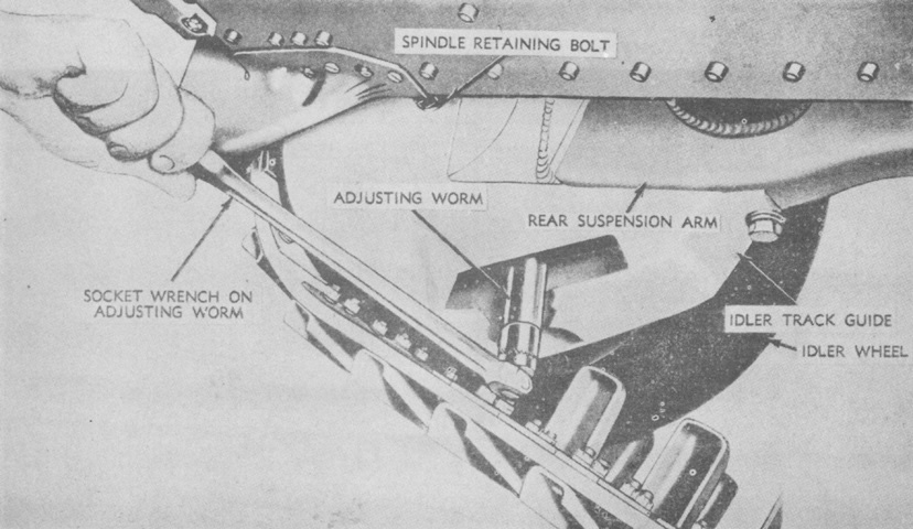
The track tension is shown here being adjusted. (Picture from TM 9-2350-213-10 C9 Operation 90-mm Full Tracked Self-propelled Gun M56.)
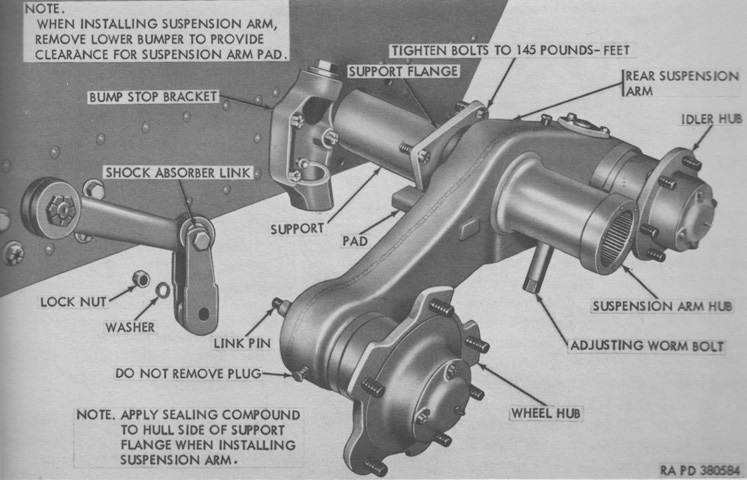
The rear suspension arm is being removed or installed in this image, and the connection between it and the shock absorber link can be gleaned. The double-acting shock absorbers were installed inside the hull on the inner ends of the wheel spindles. (Picture from TM 9-2350-213-20 Organizational Maintenance 90-mm Full Tracked Self-propelled Gun M56.)
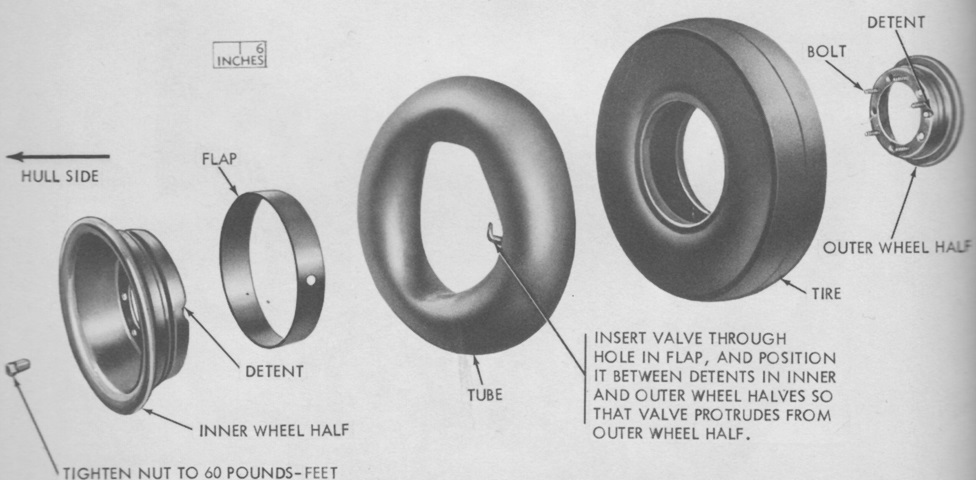
The road wheels were shod with smooth-tread, combat-type 12-ply nylon 7.50x12 pneumatic tires. An exploded view of a road wheel and tire is given in this picture. (Picture from TM 9-2350-213-20 Organizational Maintenance 90-mm Full Tracked Self-propelled Gun M56.)
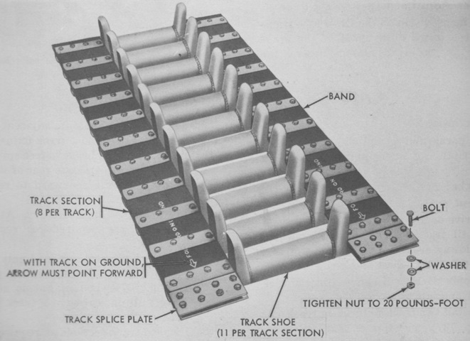
Each section of track was composed of two rubber belts with fabricated steel cables. The track shoes were steel, and ears were welded to the shoes to act as outside guides for the wheels. Rubber blocks were bonded with the outside of the track. (Picture from TM 9-2350-213-20 Organizational Maintenance 90-mm Full Tracked Self-propelled Gun M56.)
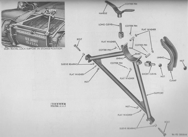
Parts of the travel lock are diagrammed in this image. When stowed, the handle needed to be flat to ensure the gun could achieve its full depression. (Picture from TM 9-2350-213-20 Organizational Maintenance 90-mm Full Tracked Self-propelled Gun M56.)
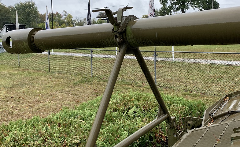
The 90mm gun's travel lock is engaged here, and the blast deflector counterweight is present at the end of the gun tube.
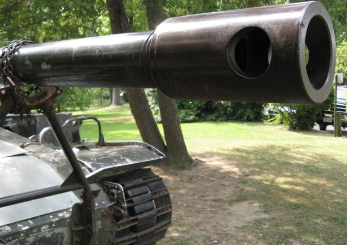
The cylindrical blast deflector counterweight is highlighted here.
