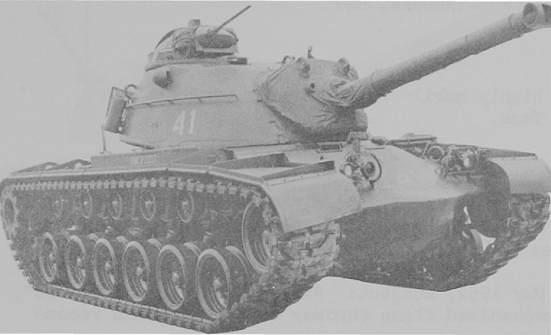
Flame Thrower Tank M67.
Compared to the M48A1 on which it was based, the M67 had a stubbier main armament. This dummy gun tube concealed the flame gun so the flame thrower tanks weren't singled out as targets. The headlight brush guards had flattened tops to allow the tube to clear at its extreme 12° of depression. (Picture from Standard Military Vehicle Characteristic Data Sheets.)
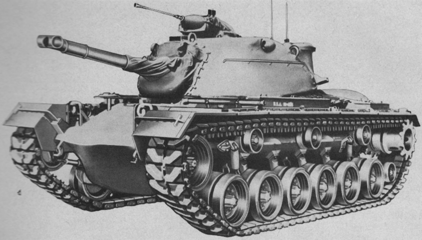
The three return rollers, infrared-suppressing hull rear, headlight clusters and guards, fender cross-section, and single personnel heater exhaust pipe exiting to the driver's left are indicative of the M48A2's parentage of the M67A1. (Picture from TM 3-1040-206-30.)
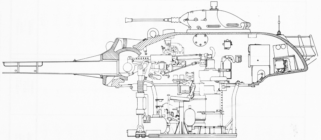
A cross-section of the turret is sketched here. (Picture from TM 3-1040-206-35P.)
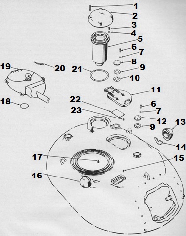
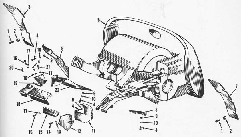
Turret attachments are labeled in this drawing. 1. Screw. 2. Ventilating blower cover. 3. Screw. 4. Washer. 5. Ventilating blower. 6. Bolt. 5. Lockwasher. 8. Antenna base cover. 9. Gasket. 10. Adapter. 11. Loader's hatch. 12. Antenna base cover. 13. Blister. 14. Shield. 15. Dowel pin. 16. Blister. 17. Capscrew. 18. Crash pad. 19. Machinegun mount. 20. Chain assembly. 21. Gasket. 22. Fueling instruction plate. 23. Self-tapping screw. (Picture from TM 3-1040-206-30.)
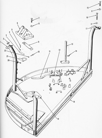
With the flame thrower fuel system replacing the loader, the turret platform was redesigned accordingly. (Picture from TM 3-1040-206-35P.)
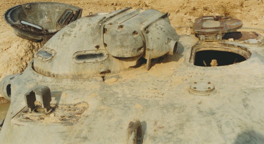
Details of the commander's M1 cupola can be seen here. Although the loader's hatch remained, his position was taken up by the flame thrower's fueling and charging controls. Note that the gunner's periscope guard is a different shape compared to the gun tanks. The M67A1 was fitted with the periscopic sight XM30. (Photo by Richard S. Eshleman.)
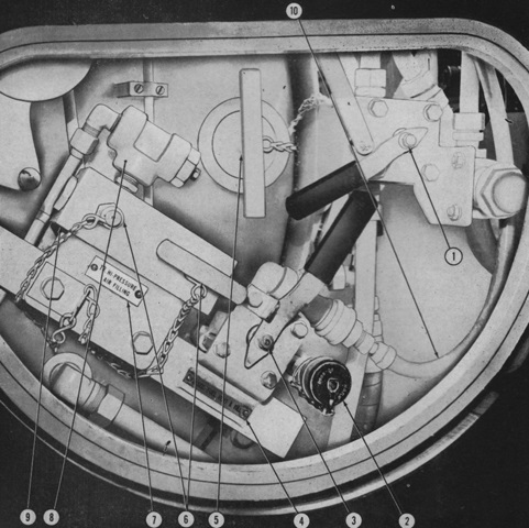
The flame thrower filling and pressure charging connections could be accessed through the loader's hatch. 1. Main fuel vent valve 1. 2. Secondary fuel fill connection. 3. Secondary fuel vent and fill valve 2. 4. Secondary fuel vent and fill nameplate. 5. Main fuel fill plug. 6. High-pressure inlet caps. 7. Hi-pressure air filling nameplate. 8. ½ inch (1.3cm) angle strainer. 9. Air-charging header 13. 10. Secondary fuel container vent hose. (Picture from TM 3-1040-206-30.)
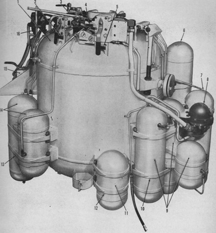
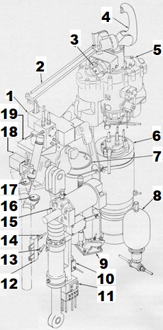
The main fuel and pressure containers are detailed in this picture. 1. Main fuel container. 2. Name plate. [sic] 3. Air charging header assembly. 4. Nameplate. 5. Nameplate. 6. Pressure container. 7. Pressure container. 8. Large volume regulator. 9. Pressure container. 10. Pin and strap. 11. Vertical pressure container. 12. Pin and strap. 13. Pin and strap. 14. Pressure container. 15. Bypass vent valve 15. 16. Relief valves. (Picture from TM 3-1040-206-30.)
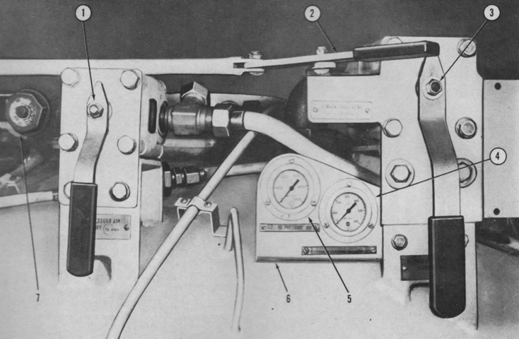
The controls mounted on the main fuel container are: 1. High pressure air shutoff valve 5. 2. Main fuel vent valve 1 remote control handle. 3. Main fuel pressure shutoff valve 6. 4. Fuel pressure setting gage 7. 5. High-pressure air gage 12. 6. Mounting plate. 7. ¾-inch (1.9cm) angle strainer. (Picture from TM 3-1040-206-30.)
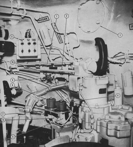
The right side of the turret is shown here, with the fuel pressure regulators and gages labeled. The commander's position is to the right of the image, with his vertically-oriented control handle visible, and the gunner would be seated to the left. Note that the rangefinder normally found in gun tanks is absent, and its apertures have been blanked off. 1. Mounting plate. 2. Secondary fuel pressure gage 10. 3. Sealing plate. 4. Secondary fuel pressure regulator 8. 5. Support bracket. 6. Support bracket. 7. Regulator mounting bracket. 8. Pilot fuel pressure regulator 3. 9. Secondary fuel pressure shutoff valve 9. 10. Fuel air pressure gage 4. 11. Gunner's control switchbox assembly. (Picture from TM 3-1040-206-30.)
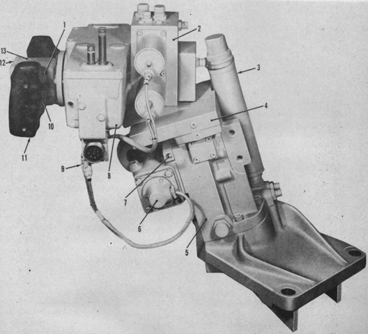
The gunner's control box assembly is detailed in this picture. 1. Trigger firing switch. 2. Hydraulic valve assembly. 3. Hand elevation pump accumulator assembly. 4. Control valve manifold. 5. Riser assembly. 6. Hand elevation pump assembly. 7. Shuttle valve assembly. 8. Housing assembly. 9. Harness assembly. 10. Magnetic brake switch. 11. Handle assembly. 12. Cover. 13. Gunner's control box assembly. (Picture from TM 3-1040-206-30.)
Parts of the elevating and traversing system are labeled in this schematic. 1. Gunner's control assembly. 2. Commander's control linkage. 3. No-back assembly. 4. Commander's control handle. 5. Turret traversing mechanism. 6. Power pack assembly. 7. Main accumulator assembly. 8. Equilibrator accumulator. 9. Hand supercharge pump. 10. Filter. 11. Elevating mechanism. 12. Equilibrator manifold assembly. 13. Shutoff valve. 14. Shutoff valve. 15. Equilibrator. 16. Equilibrator pressure gage. 17. Accumulator pressure gage. 18. Deck clearance valve. 19. Riser assembly. (Picture from TM 3-1040-206-30.)
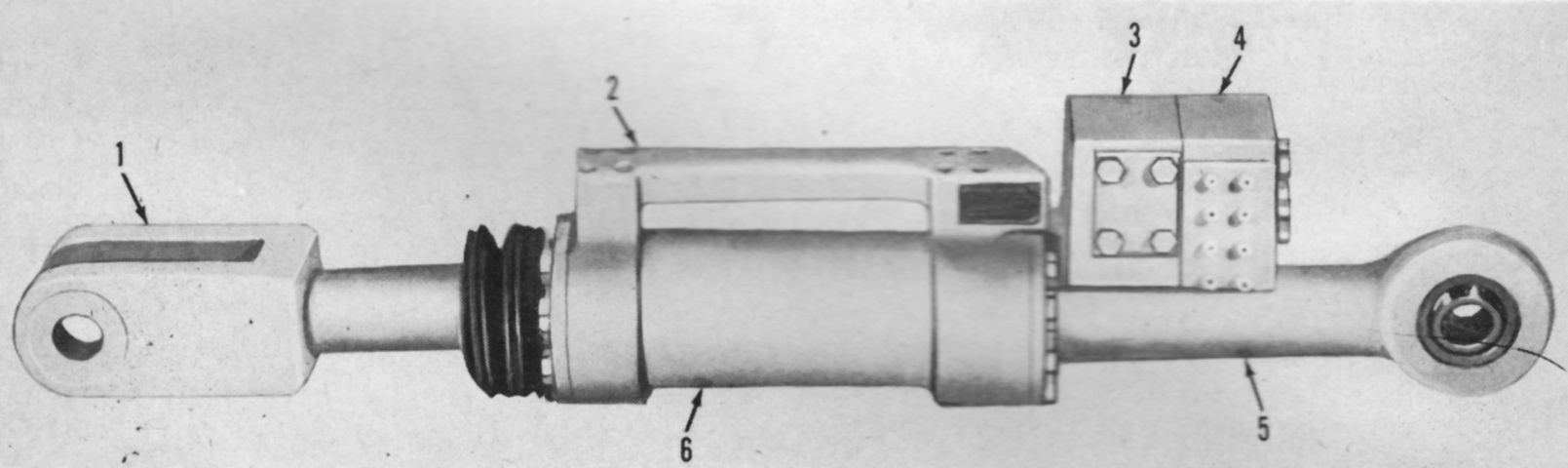
The elevating mechanism itself is shown here. 1. Clevis. 2. Manifold. 3. Relief valve assembly. 4. Lock valve assembly. 5. Sleeve assembly. 6. Cylinder. (Picture from TM 3-1040-206-30.)
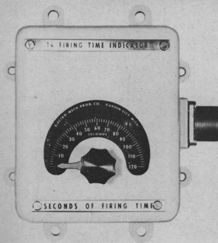
The gunner was provided with an indicator mounted to his left that showed the remaining firing time in seconds. The scale went from 0 to 120 seconds. (Picture from TM 3-1040-206-30.)
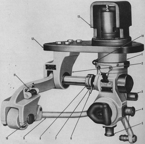
The gunner's XM30 periscope is shown here from the front in its mount XM113. It was a 1.5x magnification unit with a 48° horizontal field of view and a maximum 75° vertical field of view (60° elevation and 15° depression). 1. XM30 periscope. 2. XM113 periscope mount. 3. T25 instrument light. 4. Azimuth (deflection) boresight knob. 5. Elevation boresight knob. 6. Coupling lever. 7. Input coupling. 8. Output coupling. 9. Link assembly. 10. Double eccentric. 11. Level vial. 12. Adapter plate assembly. 13. Ballistic guard. 14. Locking handle. (Picture from TM 3-1040-206-30.)
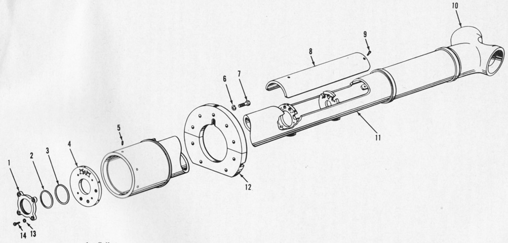
Parts of the dummy gun tube are labeled in this drawing. 1. Collar. 2. Preformed packing. 3. Preformed packing. 4. Rear bulkhead. 5. Setscrew. 6. Lockwasher. 7. Capscrew. 8. Barrel cover. 9. Capscrew. 10. Dummy blast deflector. 11. Dummy gun tube. 12. Flame gun cover. 13. Washer. 14. Screw. (Picture from TM 3-1040-206-30.)
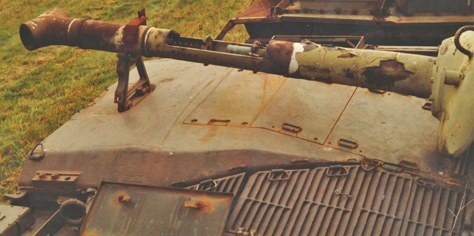
This interesting view shows some details of the flame gun where the barrel cover has been removed. The disc-like bulkhead would normally house the atomizer nozzle near the top, the main fuel nozzle extension through the large central hole, and the carbon dioxide snuffer outlet near the bottom; however, these are all missing from this vehicle. Note the air holes in the barrel shroud forward of the bulkhead and the engine access doors in the top of the insulated rear deck. (Photo by Richard S. Eshleman.)
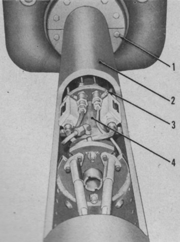
Parts are labeled in this view into the gun tube with the cover removed. 1. Gun shield cover. 2. Flame gun barrel. 3. Setscrew. 4. Main fuel tube. (Picture from TM 3-1040-206-30.)
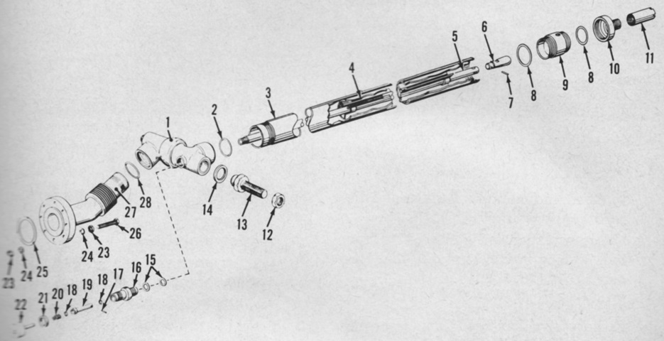
An exploded view of the flame gun is provided here. 1. Ball bearing swivel joint. 2. O-ring. 3. Main fuel tube. 4. Barrel and vane assembly. 5. Pintle rod. 6. Pintle nose. 7. Locking pin. 8. O-ring. 9. Nozzle adapter. 10. Main fuel nozzle. 11. Fuel discharge tube. 12. Nut. 13. Trunnion bearing screw. 14. Thrust washer. 15. O-ring. 16. Air cylinder housing. 17. Locking pin. 18. O-ring. 19. Air cylinder piston. 20. Air cylinder spring. 21. O-ring. 22. Air cylinder cap. 23. Nut. 24. Lockwasher. 25. Copper gasket. 26. Bolt. 27. Expansion joint. 28. O-ring. (Picture from TM 3-1040-206-30.)
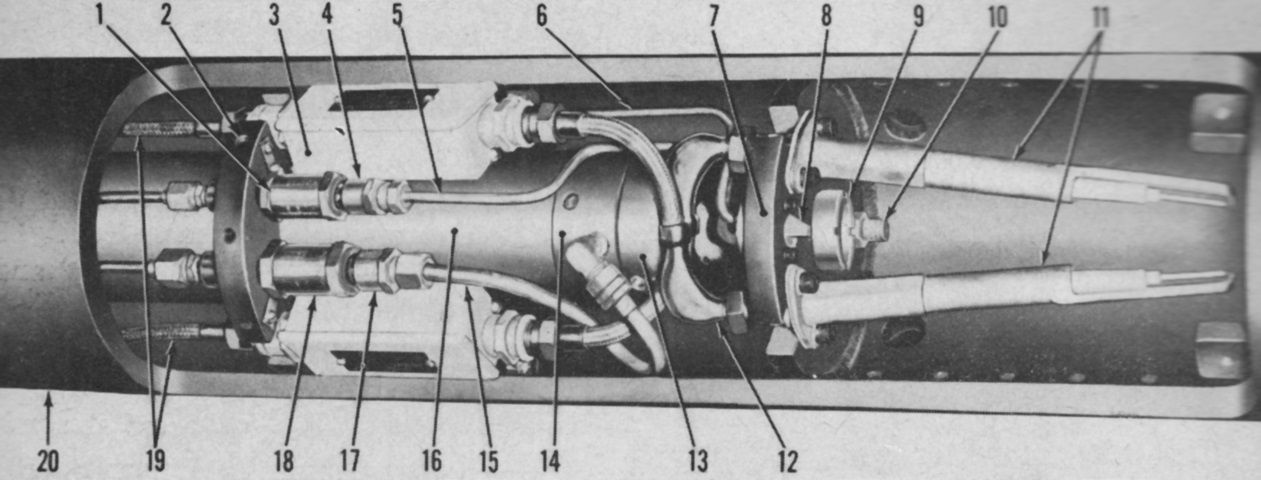
The ignition chamber was found in the forward part of the flame gun barrel, and was separated from the rest of the gun barrel by a bulkhead through which the main fuel line and the two high-voltage (2000 volt AC input to 24,000 volt AC output) spark plugs protruded. 1. Atomize fuel check valve. 2. Setscrew. 3. Compositor. 4. Female body connector. 5. Atomize fuel line. 6. Atomize air line. 7. Front bulkhead. 8. Flame gun nozzle assembly. 9. Main fuel discharge tube. 10. Snuffer outlet. 11. High-voltage spark plugs. 12. High-tension leads. 13. Main fuel nozzle. 14. Nozzle adapter. 15. Secondary fuel tube assembly. 16. Main fuel tube. 17. Female body connector. 18. Secondary fuel check valve. 19. Low tension leads. 20. Flame gun barrel. (Picture from TM 3-1040-206-30.)
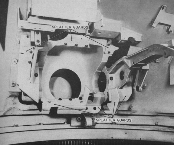
Inside the turret around the flame gun aperture, splatter guards were mounted to protect the crew and interior equipment from bullet and shrapnel splash. Note the cradle and aperture for the coaxial machine gun on the right side of the gun shield. (Picture from TM 3-1040-206-35P.)
The splatter guards are seen installed. (Picture from TM 3-1040-206-30.)
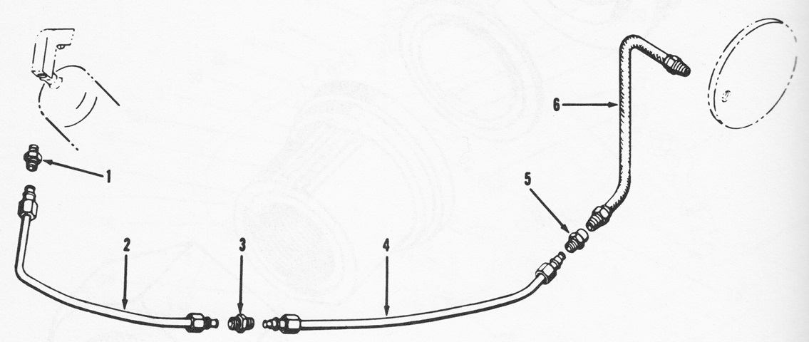
Carbon dioxide was used to snuff out flames in the gun shroud when the fuel was turned off, and the snuffer cylinder and tubing are diagrammed in this drawing. (Picture from TM 3-1040-206-35P.)
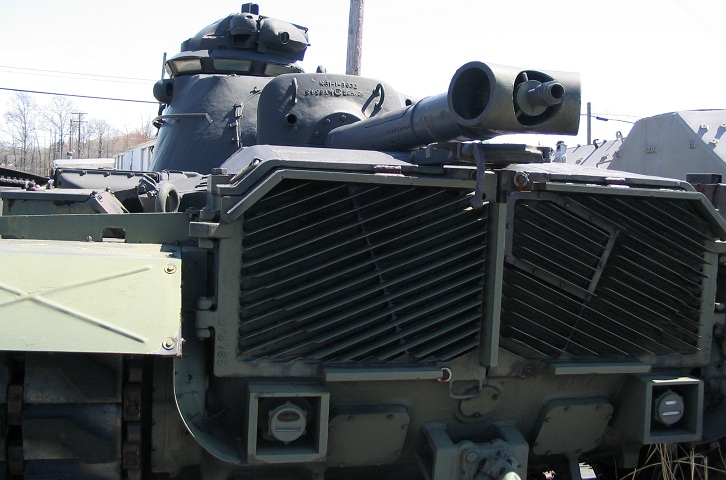
The heritage of the M48A3 tank can easily be seen in this rear view. The TC's cupola has the vision block adapter ring, and the armored boxes around the taillights and armor along the top of the exhaust grille are present. The flame gun nozzle, which could be either .75" (1.9cm) or .875" (2.22cm) diameter, is sticking out of the dummy gun tube. The removable cover on top of the dummy tube can be seen about halfway down, and the holes for combustion air line the lower portion of the tube.
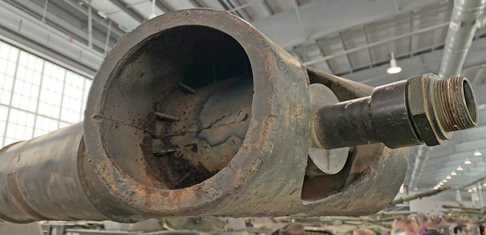
A closer view of the nozzle emanating from the dummy muzzle brake is provided in this image.
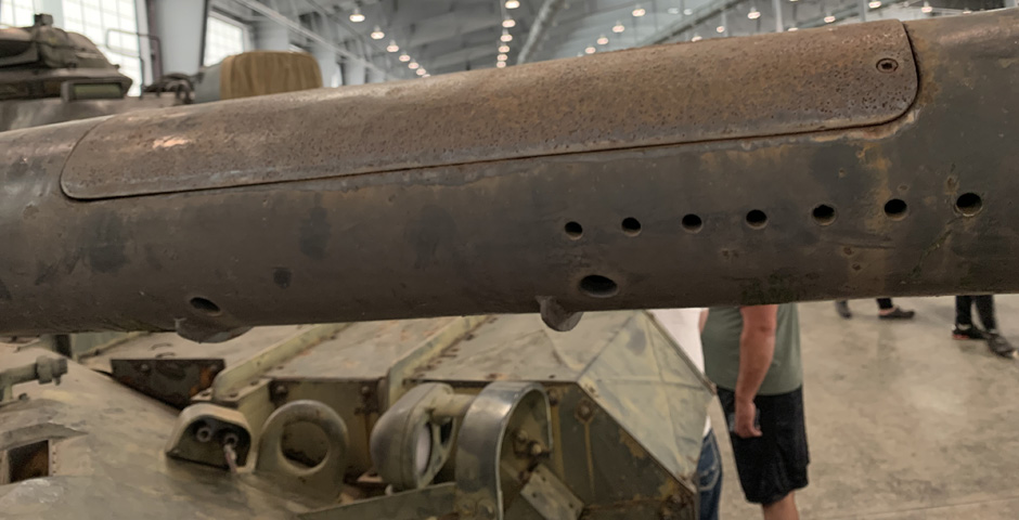
The access cover in the dummy gun tube is in place here, and the combustion and drainage holes and shields are visible on the underside of the tube.
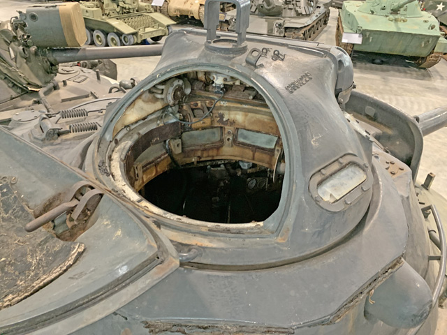
The commander's cupola on this tank is sitting on the vision block riser introduced with the M48A3 (Mod B) gun tank. Though hazy, the vision blocks can be seen through the open cupola door.
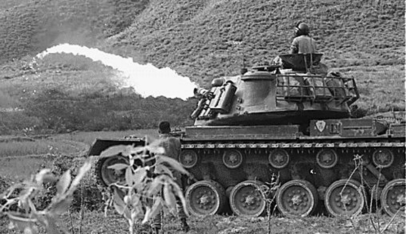
This M67A2 is being used to fearsome effect. (Picture taken Apr 1966; available from the National Archives.)
