Field Artillery Ammunition Support Vehicle M992.
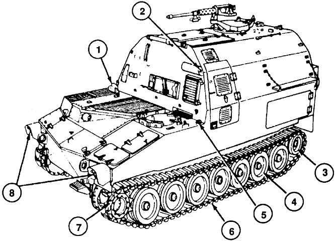
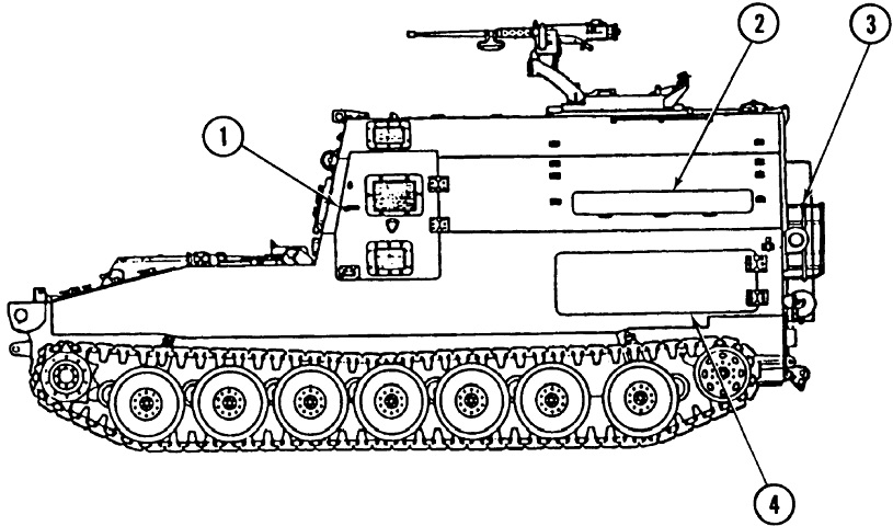
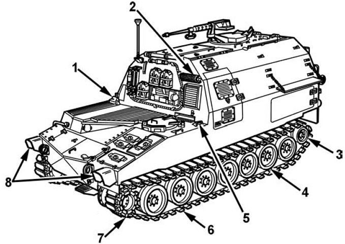
The front of the vehicle is shown here. 1. Main engine exhaust outlet. 2. APU engine exhaust outlet. 3. Idler wheel. 4. Roadwheels. 5. Lanyard cable pull handle [for manual discharge of the fire extinguishers]. 6. Track. 7. Drive sprocket. 8. Headlamps. (Picture from TM 9-2350-267-10 C1.)
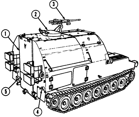
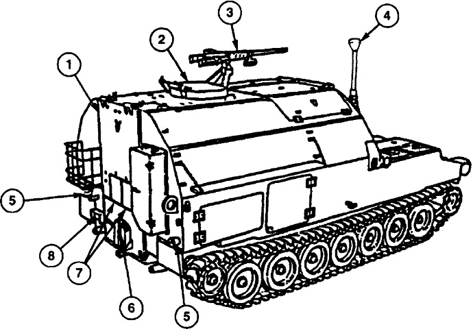
The rear of the vehicle is sketched here. 1. Upper rear door (ballistic shield). 2. Commander's cupola. 3. Machine gun. 4. Taillight/stoplight. 5. NATO slave receptacle. (Picture from TM 9-2350-267-10 C1.)
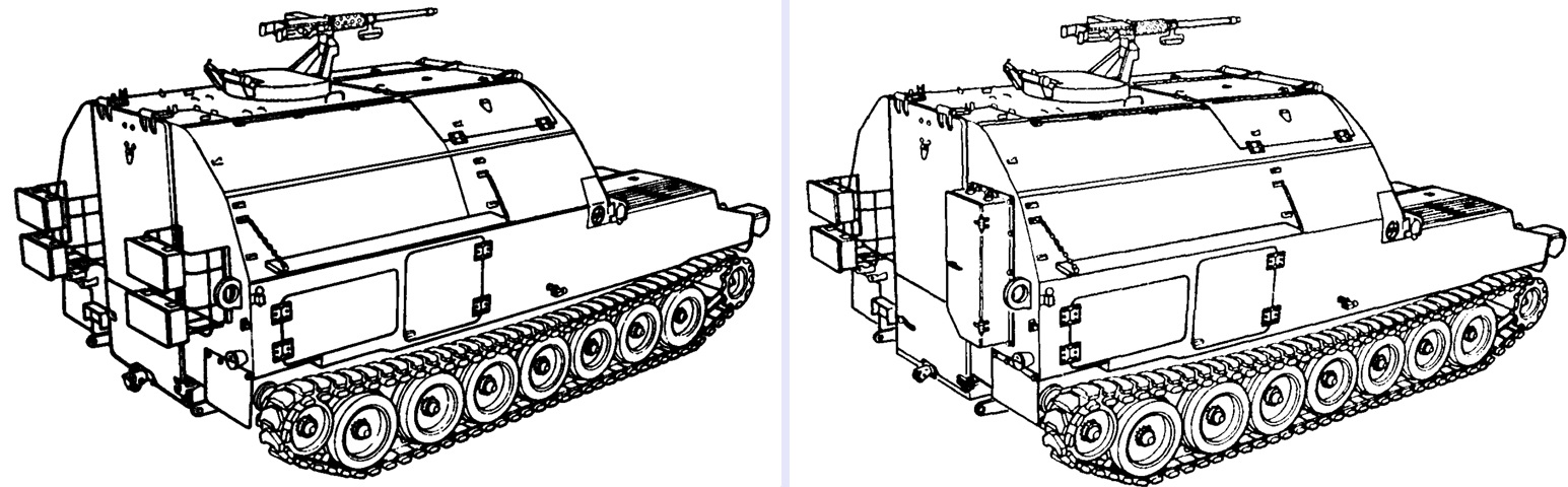
Beginning with vehicle number 345, as shown on the right, the right rear stowage racks were deleted for a new crew automatic fire extinguisher box assembly. (Picture from TM 9-2350-267-10 C1.)
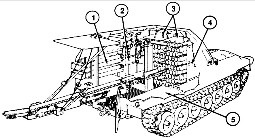
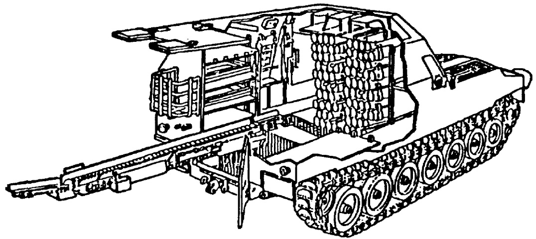
This image shows a cross-section of the interior with the rear doors opened and the conveyor deployed. The numbers show that propellant canisters can be stowed 1. in the left rear shelf area, 2. on left sponson, 3. above projectile racks, 4. in the right front shelf area, and 5. in the right rear shelf area. (Picture from TM 9-2350-267-10 C1.)
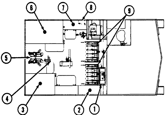
The crew and cargo compartment is shown here, with the vehicle facing to the right. 1. Hydraulic reservoir. 2. Right front charge canister stowage shelves. 3. Right rear charge canister stowage shelves. 4. Commander's seat. 5. Conveyor. 6. Left rear charge canister stowage area. 7. Left front charge canister stowage area. 8. Hydraulic system control panel. 9. Projectile rack assembly. (Picture from TM 9-2350-267-10 C1.)
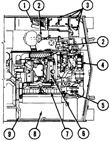
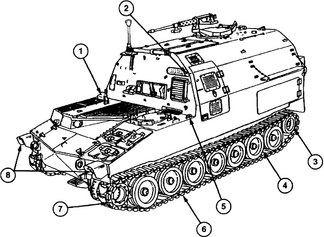
The engine compartment is drawn in this picture, again with the vehicle facing right. 1. Driver's controls and indicators. 2. Driver's steering controls. 3. Batteries. 4. Transmission. 5. Final drive assemblies. 6. Main engine. 7. Cooling fans and radiator. 8. Upper and lower fuel tanks. 9. Main engine exhaust system. (Picture from TM 9-2350-267-10 C1.)
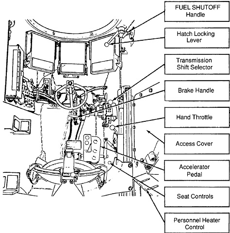
The driver's compartment is detailed in this drawing. (Picture from TM 9-2350-267-10 C1.)
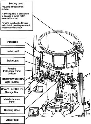
The other side of the driver's compartment is shown. (Picture from TM 9-2350-267-10 C1.)
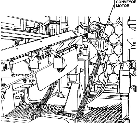
The front of the conveyor is shown here. The ammunition stacker and projectile racks are in the background. (Picture from TM 9-2350-267-10 C1.)
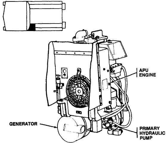
The Onan Model DJEAM auxiliary power unit engine and its location are shown here. The vehicle is facing left in the inset. The APU was an overhead valve, 2-cylinder, 4-cycle 70in³ (1150cm³) diesel engine that made 11.5 horsepower at 2000rpm. (Picture from TM 9-2350-267-10 C1.)
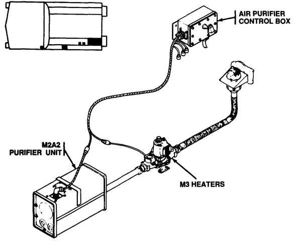
The NBC filter system provided was composed of an air purifier unit M2A2, its control box, four mask hose couplings, and four heaters M3. The air purifier M2A2 contained a particulate filter M13, gas filter M12A1, and an air purifier precleaner M1A1 in a single steel housing. Crew could connect their individual M25A1 face pieces to the system and use the heaters M3 to adjust the air temperature to their liking; due to risk of lung damage from cold air, the heaters had to be operated for at least 15 minutes before connection with the M25A1 masks when the outside temperature was under 40°F (4°C). (Picture from TM 9-2350-267-10 C1.)
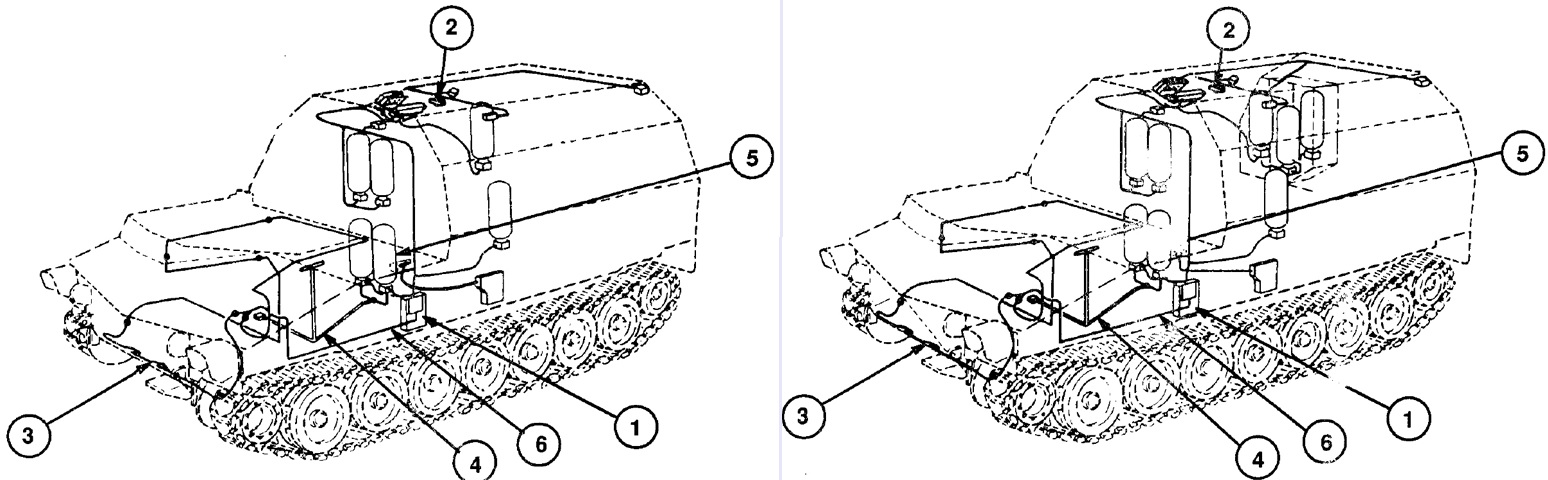
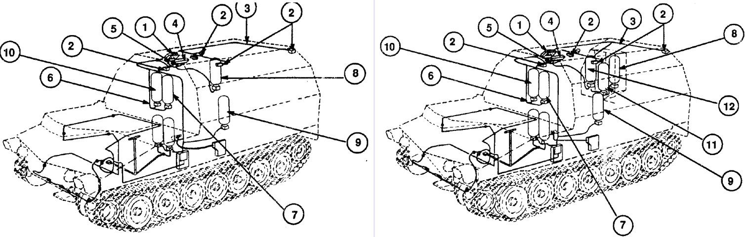
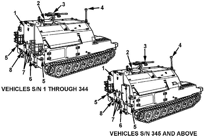
An automatic fire extinguishing system was installed that provided capability to automatically detect and extinguish hydrocarbon fires in both the crew and engine compartments; manual operation was available as well. The engine extinguisher system components are diagrammed here, with the first 344 vehicles to the left and vehicles 345 and above on the right. The two extinguishers were filled with Halon pressurized with dry nitrogen; extinguisher number one was interfaced with the thermal detection system through the engine compartment test/alarm panel, while the other was actuated by pulling the external handle near the driver's hatch. 1. Engine test/alarm panel. 2. Remote sensor indicator. 3. Thermal detection system. 4. Halon distribution system. 5. Engine fire extinguisher no.1. 6. Extinguisher wire harness W4. (Picture from TM 9-2350-267-10 C1.)
The crew compartment fire extinguisher system is labeled here, again with vehicles 1-344 on the left. The crew compartment system had the option of automatically releasing a second shot after five seconds if the fire was not extinguished or if a second fire erupted. The early vehicles had four 10lb (4.5kg) cylinders filled with Halon 1301 pressurized with dry nitrogen, while vehicles 345 and later had six 7lb (3.2kg) cylinders. In each case, two extinguishers were reserved for manual activation by the external handle or the manual electric discharge toggle switch, or automatic discharge if the fire continued or a second fire began. In addition, two portable CF3Br extinguishers were located in the crew compartment, one on the lower rear door and the second on the right-side canister rack. The portable extinguishers would work on fuel as well as electrical fires. 1. Crew test/alarm panel. 2. Optical fire sensing assembly. 3. Optical fire sensing assembly wire harness W1. 4. Standard control electronic amplifier. 5. Standard control electronic amplifier wire harness W2. 6. Extinguisher wire harness W3. 7. Crew fire extinguisher no.1. 8. Crew fire extinguisher no.2. 9. Crew fire extinguisher no.3*. 10. Crew fire extinguisher no.4*. 11. Crew fire extinguisher no.5. 12. Crew fire extinguisher no.6.
*Activated manually or automatically. (Picture from TM 9-2350-267-10 C1.)
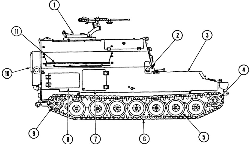
This vehicle can be contrasted to the earlier version above. 1. Main engine exhaust outlet. 2. APU engine exhaust outlet. 3. Idler wheels. 4. Roadwheels. 5. Lanyard cable pull handle [for manual discharge of the fire extinguishers]. 6. Tracks. 7. Drive sprockets. 8. Headlamps. (Picture from TM 9-2350-287-10 C1.)
Note the changes to the rear doors and stowage. The small upper doors allow the conveyor to be deployed with the upper rear door closed. 1. Upper rear door (ballistic shield). 2. Commander's cupola. 3. Machine gun. 4. AN/PSN-11 Precision Lightweight GPS Receiver. 5. Taillight/stoplight. 6. M13 portable decontaminating apparatus. 7. Small upper doors. 8. Rear NATO slave receptacle. (Picture from TM 9-2350-287-10 C1.)
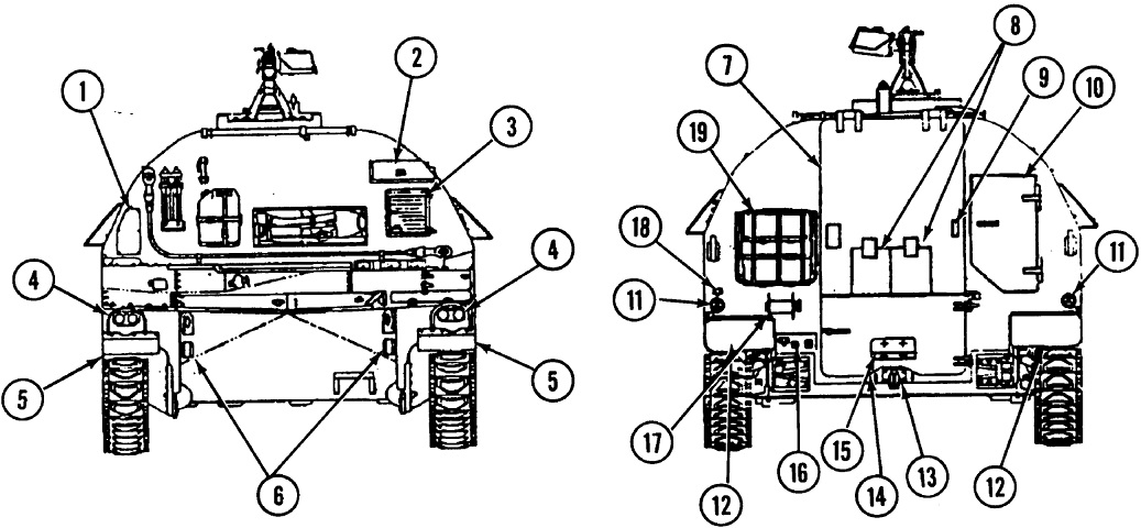
Further details of the front and rear of the vehicle are drawn in this image. 1. Fuel filler access plate. 2. APU muffler. 3. APU air inlet door. 4. Headlights. 5. Fenders. 6. Towing lugs. 7. Upper rear door. 8. Upper rear door small doors. 9. Small door latches. 10. Crew automatic fire extinguisher system fire extinguisher box assembly. 11. Taillights. 12. Fenders. 13. Tow pintle. 14. Lower rear door. 15. M13 decontamination apparatus. 16. NBC terminals, NATO intervehicle slave connector, and trailer receptacle. 17. Telephone handreel. 18. Telephone terminals. 19. Stowage rack. (Picture from TM 9-2350-287-20-1 C1.)
The left side of the vehicle is drawn here. 1. APU door. 2. Duffle bag stowage rack. 3. Stowage rack. 4. Canister door/Copperhead projectiles. (Picture from TM 9-2350-287-20-1 C1.)
1. Commander's cupola. 2. Fuel fill access door. 3. Hull. 4. Drive sprocket. 5. Roadwheel. 6. Track. 7. Personnel side door. 8. Canister side door. 9. Idler wheel. 10. Crew automatic fire extinguisher system fire extinguisher box assembly. 11. Duffle bag stowage rack. (Picture from TM 9-2350-287-20-1 C1.)
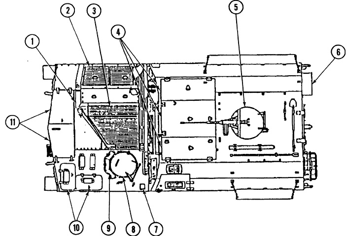
The top of the vehicle is illustrated here. 1. Engine deck access plates. 2. Engine access cover. 3. Air intake grille. 4. Top doors. 5. Commander's cupola. 6. Crew automatic fire extinguisher system fire extinguisher box assembly. 7. Automatic fire extinguisher system manual discharge system lanyard cable pull handle. 8. Driver's hatch. 9. Driver's periscope assembly. 10. Battery access covers. 11. Transmission access covers. (Picture from TM 9-2350-287-20-1 C1.)
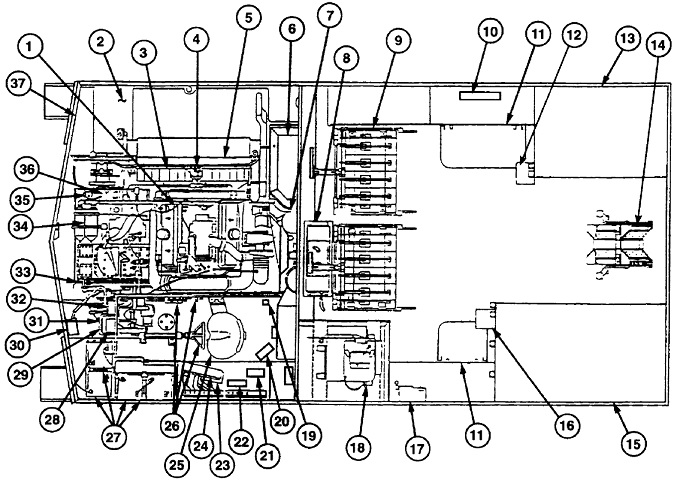
This top-down view details the interior of the vehicle. 1. Engine. 2. Fuel tanks and pumps. 3. Radiator. 4. Generator. 5. Fan assembly. 6. Air cleaner. 7. Personnel heater. 8. Hydraulic fluid reservoir. 9. Projectile rack assemblies. 10. Crew automatic fire extinguisher system test and alarm panel. 11. Crew seats. 12. Precision Lightweight GPS Receiver. 13. Right canister compartment shelf assembly. 14. Conveyor assembly. 15. Left canister compartment shelf assembly. 16. Mounted water ration heater. 17. Hydraulic control panel. 18. APU. 19. Air cleaner restriction indicator. 20. Personnel heater control box. 21. Automatic fire extinguisher system manual discharge system actuator assembly. 22. Engine automatic fire extinguisher system test and alarm panel. 23. Driver's compartment NATO slave receptacle. 24. Main and portable instrument panels. 25. Driver's seat. 26. Driver's controls. 27. Batteries. 28. Voltage regulator. 29. Bilge pump relay. 30. Rectifier. 31. Starter relay. 32. Master relay. 33. Secondary fuel filter. 34. Engine oil filters. 35. Primary fuel filter. 36. Transmission. 37. Coolant surge tank. (Picture from TM 9-2350-287-20-1 C1.)
The conveyor is deployed in this drawing. Note that the small upper rear doors are hinged to the sides. (Picture from TM 9-2350-287-10 C1.)
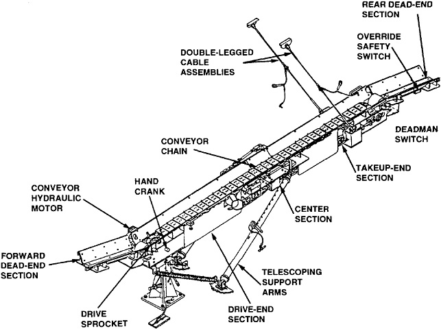
Details of the conveyor mechanism are shown here. (Picture from TM 9-2350-287-20-1 C1.)
Details of the front of the M992A2 are sketched here. 1. Main engine exhaust outlet. 2. APU engine exhaust outlet. 3. Idler wheels. 4. Roadwheels. 5. Lanyard cable pull handle [for manual discharge of the fire extinguishers]. 6. Tracks. 7. Drive sprockets. 8. Headlamps. (Picture from TM 9-2350-293-10.)
The rear is shown in this drawing. 1. Upper rear door (ballistic shield). 2. Commander's cupola. 3. Machine gun. 4. AN/PSN-11 (PLGR). 5. Taillight/stoplight. 6. M13 decontaminating apparatus, portable. 7. Dog doors. 8. Rear NATO slave receptacle. (Picture from TM 9-2350-293-10.)
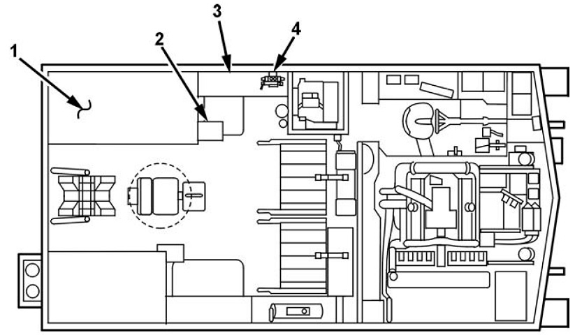
Major internal components can be located with the next two images. Note the differing locations of the personnel heater and hydraulic reservoir when compared with earlier vehicles. 1. Left rear charge canister stowage shelves. 2. Mounted water ration heater (MWRH). 3. Left front charge canister stowage area. 4. Hydraulic control panel. (Picture from TM 9-2350-293-10.)
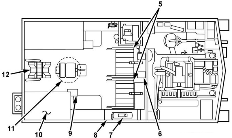
5. Projectile rack assemblies. 6. Hydraulic reservoir. 7. Personnel heater. 8. Right front charge canister stowage shelves. 9. AN/PSN-11 mount assembly. 10. Right rear charge canister stowage shelves. 11. Commander's seat. 12. Conveyor. (Picture from TM 9-2350-293-10.)
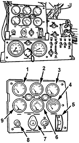
The driver was provided with a portable instrument panel so he could monitor the main engine functions while outside the vehicle. It was stowed in brackets on the main instrument panel. 1. Water temp gage. 2. Engine oil pressure gage. 3. Fuel level gage. 4. Battery gage. 5. Master switch. 6. Transmission oil pressure gage. 7. Master power indicator. 8. Coolant level indicator. 9. Transmission oil temp gage. (Picture from TM 9-2350-293-10.)
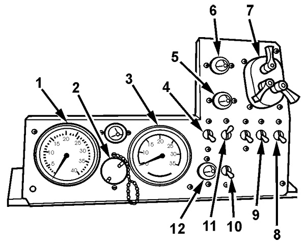
The driver's main instrument panel is sketched in this image. 1. Tachometer/hour meter. 2. Auxiliary outlet. 3. Speedometer/odometer. 4. Fuel prime switch. 5. Hi-beam indicator. 6. Parking brake indicator. 7. Service light switch. 8. Upper/lower fuel gage switch. 9. Bilge pump switch. 10. Starter switch. 11. Glow plug switch. 12. Glow plug indicator. (Picture from TM 9-2350-293-10.)
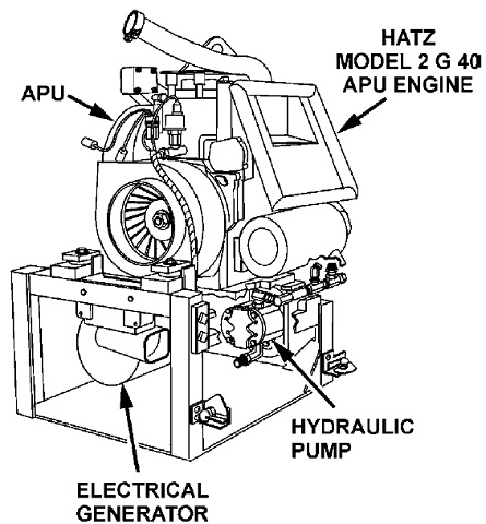
The Onan APU engine was superseded by the Hatz Model 2 G 40, a 2-cylinder, 4-cycle, 13.5-horsepower diesel engine. (Picture from TM 9-2350-293-10.)
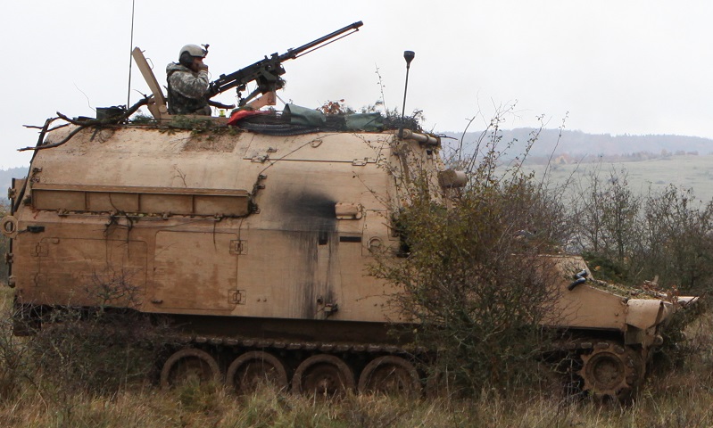
The relation of the FAASV M992A2 to the self-propelled howitzer M109A2 is immediately apparent. The turret of the howitzer was removed, and an armored superstructure was built up from the hull to contain extra howitzer ammunition. The vehicles could be backed up to one another and a conveyor system would transfer ammunition. This vehicle belonged to Charlie Battery, 1st Battalion, 82nd Field Artillery Regiment, 1st Brigade Combat Team, 1st Cavalry Division and was taking part in Exercise Combined Resolve III. Note the blank adapter on the .50cal MG. (Picture taken 6 Nov 2014 by SSG Carol A. Lehman; available from Defense Video & Imagery Distribution System.)
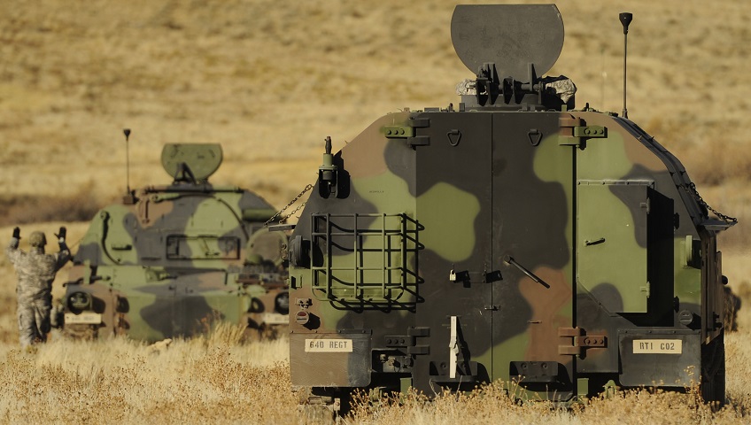
Large rear doors facilitate the transfer of artillery ammunition. The rear door opened upward in the M992 and M992A1 to provide overhead protection, but the doors were modified with the M992A2. (Picture taken 4 Nov 2011 by SSG Devin Doskey; available from Defense Video & Imagery Distribution System.)
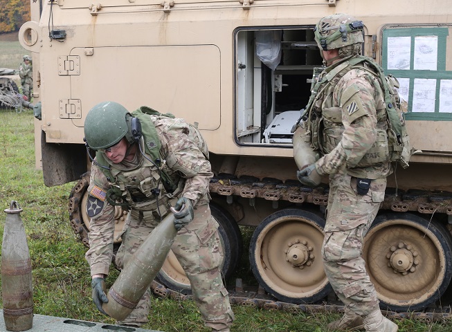
The vehicle was also provided with sponson doors for easier loading. These men are with the 1st Battalion, 41st Field Artillery Regiment, 1st Armored Brigade, 3rd Infantry Division and were taking part in Exercise Combined Resolve V. (Picture taken 25 Oct 2015 by SGT Ian Schell; available from Defense Video & Imagery Distribution System.)
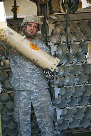
The extensive ammunition racks are illustrated behind this member of Bravo Company, 1st Battalion, 178th Field Artillery Regiment, South Carolina National Guard. (Picture taken 10 Mar 2013 by SGT Brian Calhoun; available from Defense Video & Imagery Distribution System.)
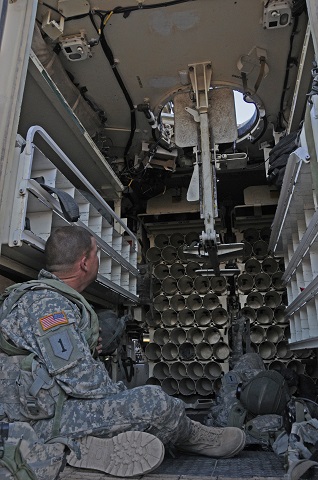
The relatively spacious interior is highlighted in this image. The commander's pedestal and seat and open hatch door can be seen in the roof. (Picture taken 22 Feb 2013 by David Vergun; available from Defense Video & Imagery Distribution System.)
