Multiple Gun Motor Carriage M14.
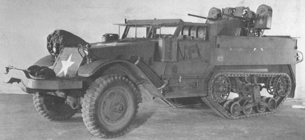
The M14 shares traits with the half-track personnel carrier M5 on which it is based, including the thin fenders and demountable headlights visible on this example. The machine gun turret can be seen in the rear compartment, and the hinged side armor running the length of the top of the passenger compartment is folded down. (Picture from Tank Data, vol. 2.)
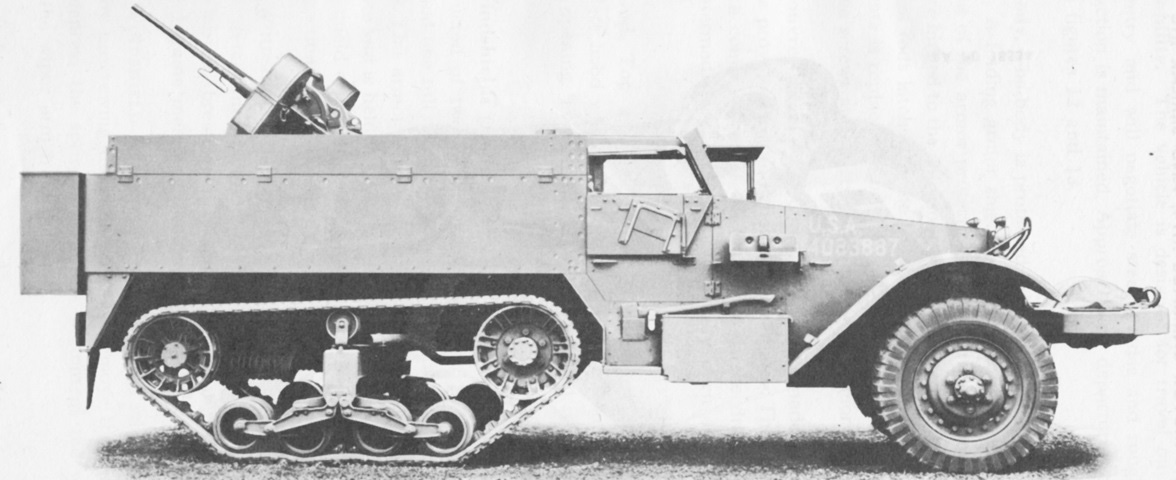
The hinged armor flaps are raised in this image. (Picture from TM 9-707 Basic Half-Track Vehicles (IHC).)
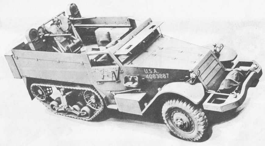
The positioning of the machine gun turret in the rear can be seen here. Absent on this vehicle is the shield that normally enveloped the gunner and lower portion of the machine gun turret. Many M14s were converted into personnel carriers as World War II progressed. (Picture from TM 9-707 Basic Half-Track Vehicles (IHC).)
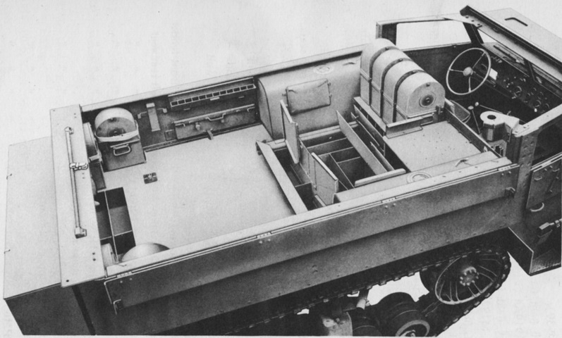
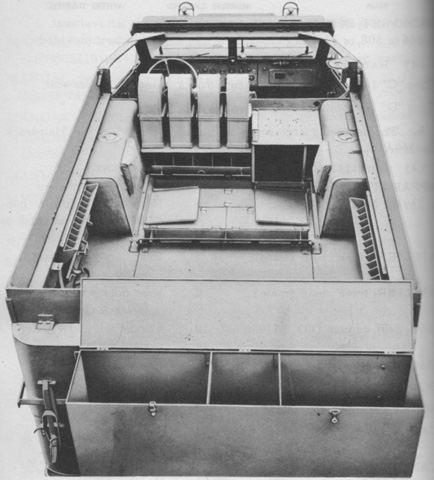
This picture illustrates where extra .50cal ammunition chests and boxes were stowed. The Maxson turret would occupy the large white space in the rear of the passenger compartment. Some underfloor stowage compartments are open to the front of the vehicle, and the hinged armor flaps are lowered on this vehicle. Due to the curved rear corners of the passenger compartment of International Harvester half-tracks, the rear folding armor flap was mounted a few inches inboard from the rear of the vehicle. This contrasts with the MGMC M13, where the rear armor flap is directly atop the rear armor. (Picture from TM 9-707 Basic Half-Track Vehicles (IHC).)
The interior of the rear stowage box can be seen here, as well as the rear and interior ledges around the hinged armor flaps. (Picture from TM 9-707 Basic Half-Track Vehicles (IHC).)
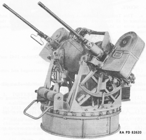
The twin caliber .50 MG mount M33 is shown here without its partial armor plates. The M33 mounted its guns via ring spring adapters; studs on the adapter casings mated with the forward mounting yoke. Guns fitted with the M33's ring spring adapters could be mounted in the quad-gun mount M45, but the M33 would not accept guns from the M45. Compared to the M45 mount, the M33 omitted a motor thermostat, overheat warning light, firing circuit relay, sight interlock switch, and circuit breaker reset button. The M33 was 72" (180cm) wide overall, 72" (180cm) high with the guns at 0° elevation, 78.5" (199cm) with the guns fully elevated, and weighed around 1,500lb (680kg) fully equipped. (Picture from TM 9-223 Twin Cal. .50 Machine Gun Mount M33 and Multiple Cal. .50 Machine Gun Mount M45.)
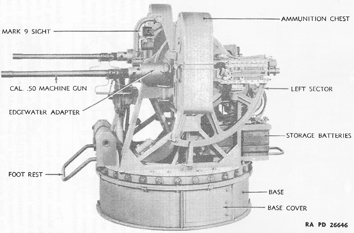
Side details of the M33 mount are labeled here. (Picture from TM 9-223 Twin Cal. .50 Machine Gun Mount M33 and Multiple Cal. .50 Machine Gun Mount M45.)
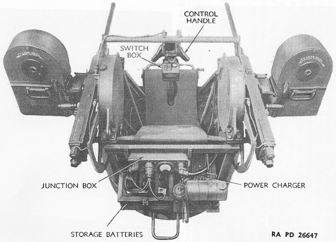
The M33 mount is shown here from above and behind. (Picture from TM 9-223 Twin Cal. .50 Machine Gun Mount M33 and Multiple Cal. .50 Machine Gun Mount M45.)
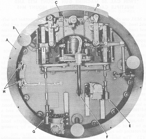
The M33 mount is seen here from its underside. A. Turret ring gear. B. Foot. C. Power drive. D. Guard. E. Elevation gear box. F. Power conduit. G. Azimuth gears. H. Azimuth interrupter switches. (Picture from TM 9-223 Twin Cal. .50 Machine Gun Mount M33 and Multiple Cal. .50 Machine Gun Mount M45.)
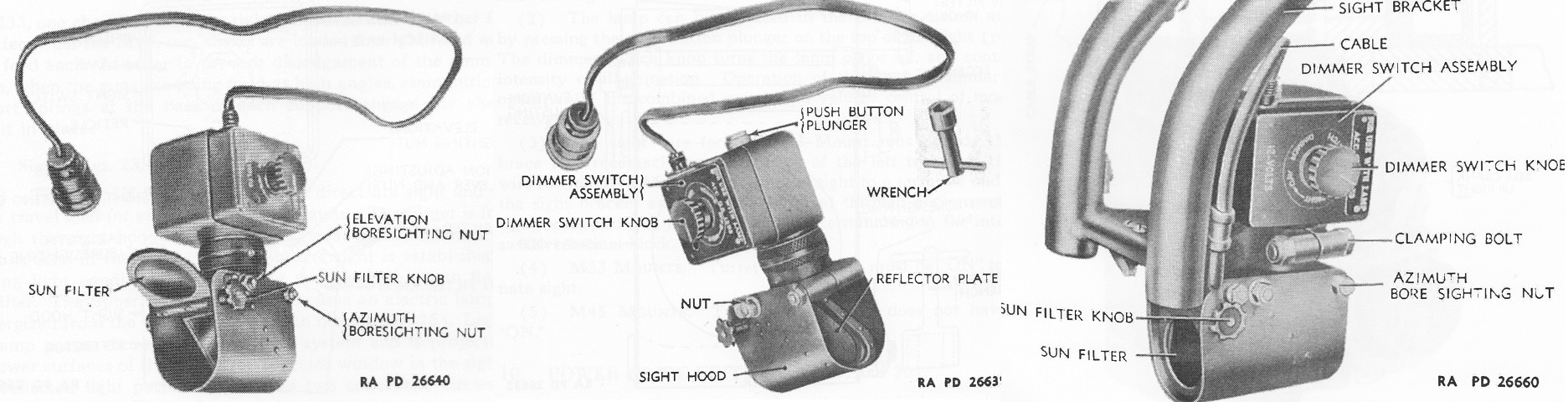
The reflector sight Mk. 9 is seen here respectively from the front, rear, and mounted to the bracket on the machine gun mount. It projected a reticle of two concentric circles and a central dot onto the reflector plate; the dimmer switch adjusted the brightness of the image. The sun filter could be rotated out of view by pressing and turning the sun filter knob. (Picture from TM 9-223 Twin Cal. .50 Machine Gun Mount M33 and Multiple Cal. .50 Machine Gun Mount M45.)
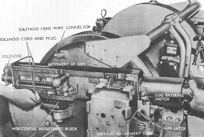
One of the two .50cal MGs is being mounted in this image. The gun was slid forward to mate the securing pin under the receiver with slots in the horizontal adjustment block, then the Edgewater adapter on the barrel was lowered so its lugs settled into the notches of the vertical adjustment yoke. The gun latches on the vertical adjustment yoke were then swung over the Edgewater adapter lugs. The M33 could be modified to accept guns fitted with barrel supports designed for the multiple gun mount M45 instead of Edgewater adapters. (Picture from TM 9-223 Twin Cal. .50 Machine Gun Mount M33 and Multiple Cal. .50 Machine Gun Mount M45.)
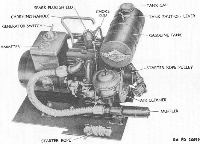
The M33 used a 300-watt, 12-volt, 4-cycle gasoline Briggs & Stratton Model 300 PC-1 for its power charger. This provided energy to the two 6-volt batteries that powered the turret drive motor, firing solenoids, and lights in the reflector sight and firing circuit indicator lamp. It could be started either electrically via its generator or manually via a pull rope. Half a gallon (2L) of fuel was carried in the tank, and if starting with fully-charged batteries, this would enable the turret to operate for 5 hours using a 5-minute on/5-minute off cycle and running the power charger continuously. (Picture from TM 9-223 Twin Cal. .50 Machine Gun Mount M33 and Multiple Cal. .50 Machine Gun Mount M45.)
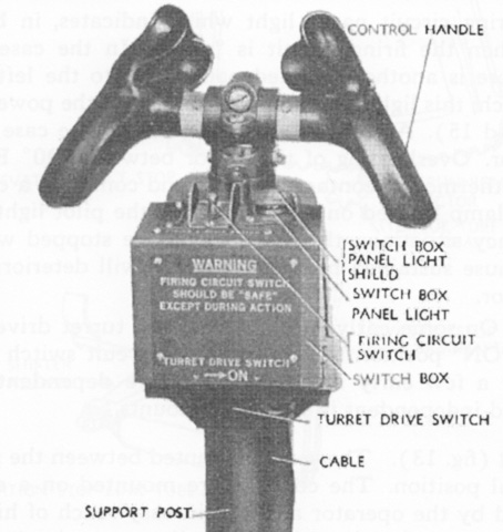
The control handles for the M33 are shown here. (Picture from TM 9-223 Twin Cal. .50 Machine Gun Mount M33 and Multiple Cal. .50 Machine Gun Mount M45.)
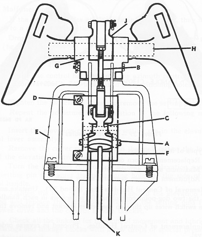
This schematic shows the inner workings of the control handles. A. Azimuth control bearing block pivot. B. Elevation control lever rod. C. Lower elevation control lever. D. Screw. E. Control support. F. Azimuth control arm. G. Azimuth control bracket. H. Elevation control lever pivot tube. J. Upper elevation control lever. K. Long lower elevation control tie rod. (Picture from TM 9-1223 Ordnance Maintenance--Twin Cal. .50 Machine Gun Mount M33 and Multiple Cal. .50 Machine Gun Mount M45.)
