Universal Carrier T16.
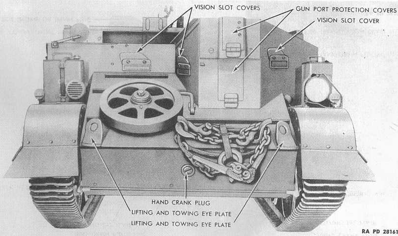
Since the T16 was intended for British use, the driver sat on the right side of the vehicle. The gunner sat beside him on the left, behind the armored shield, and two passengers could sit in the rear. (Picture from TM 9-746 Universal Carrier T16.)
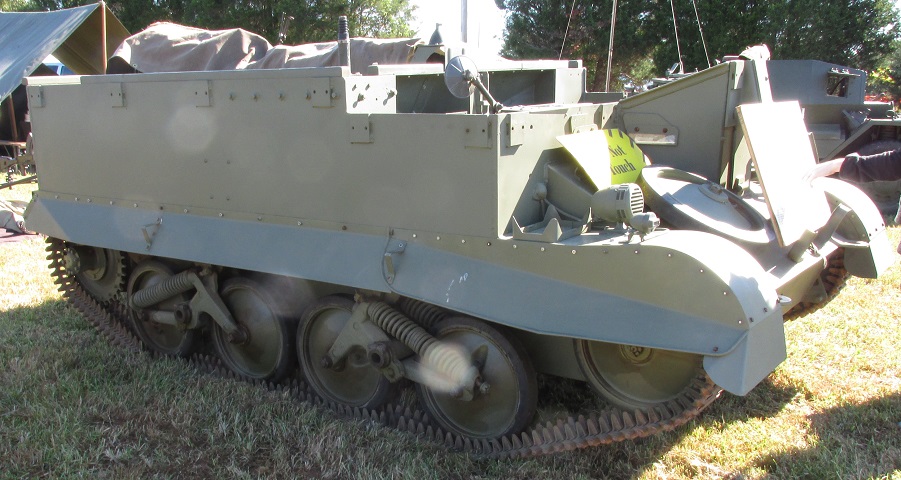
Note the orientation of the suspension springs on this machine; the rear bogie would be reversed on a T16E2. A siren is mounted on the right front fender in both images.
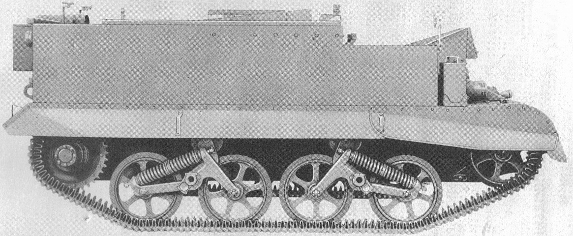
Another side view is provided here, with spoked road and idler wheels. (Picture from TM 9-746 Universal Carrier T16.)
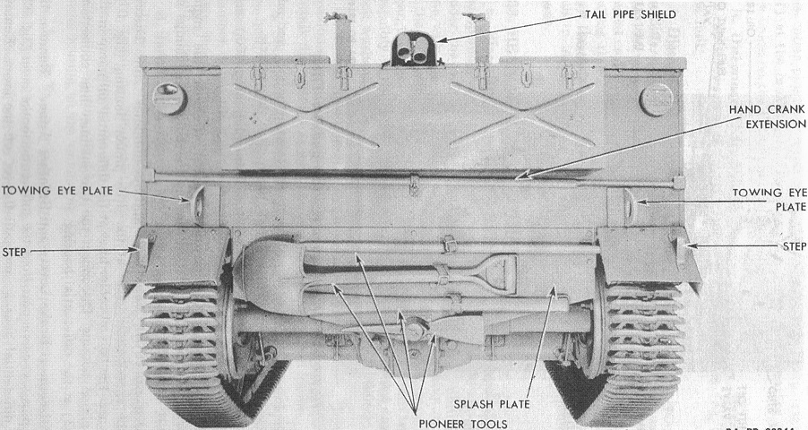
Details of the rear of the vehicle are labeled here. (Picture from TM 9-746 Universal Carrier T16.)
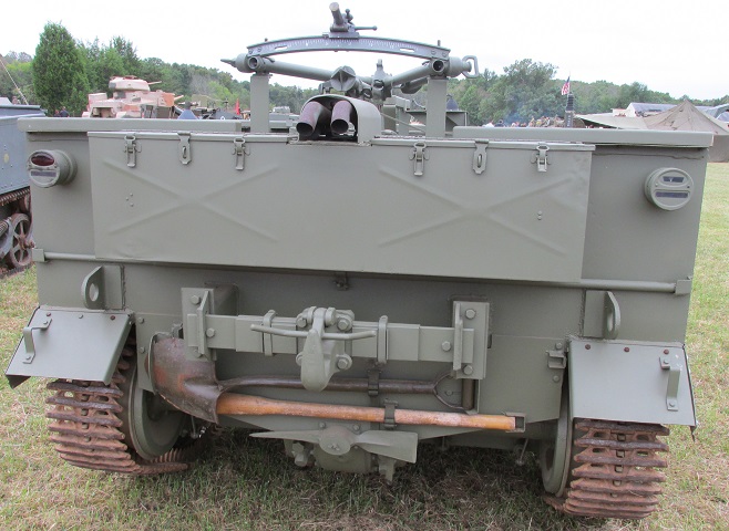
A towing hook assembly has been mounted to this carrier, and a Bren gun tripod is stowed above the stowage box.
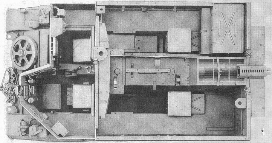
The interior is revealed in this top-down view. (Picture from TM 9-746 Universal Carrier T16.)
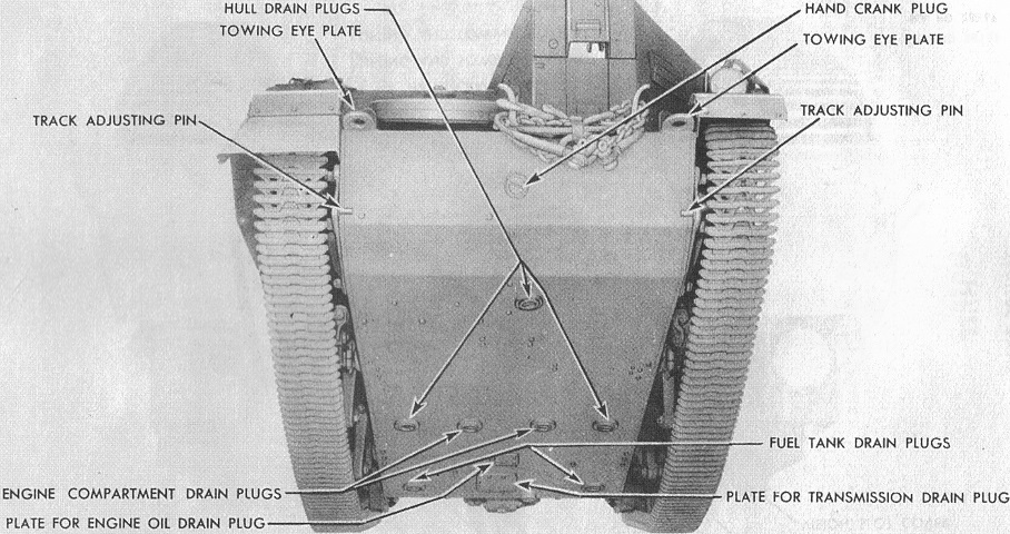
The various drain plugs on the hull bottom are labeled here. (Picture from TM 9-746 Universal Carrier T16.)
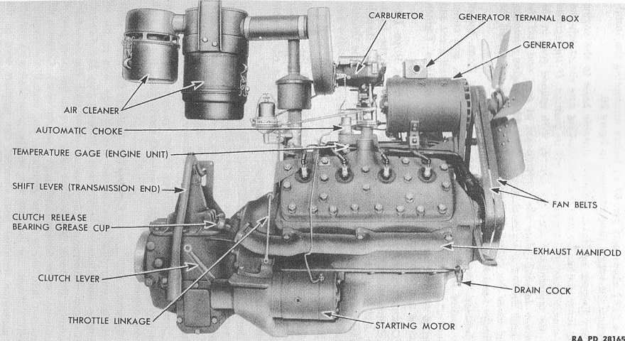
This is the right side of the GAU engine. It was a 90° L-head V-8 that weighed 725lb (329kg) with the transmission and accessories. The cylinders had a bore of 3.187" (8.095cm) and a stroke of 3.75" (9.53cm) for a displacement of 239in³ (3920cm³). Its compression ratio was 6.4:1. (Picture from TM 9-746 Universal Carrier T16.)

The engine is installed in this picture, and the covers have been removed. (Picture from TM 9-746 Universal Carrier T16.)
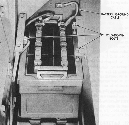
A 12-volt storage battery was installed to the right of the engine at the front of the passenger compartment. It is seen here with the cover removed. (Picture from TM 9-746 Universal Carrier T16.)
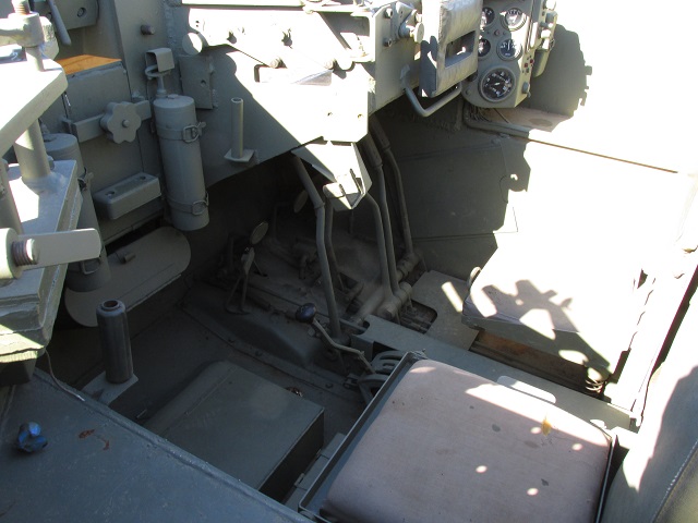
The driver's and gunner's positions are shown here. Both seats were adjustable, and both men were provided with shuttered vision slots. Two cylindrical CCl4 fire extinguishers are stowed vertically to the gunner's front; another was carried on top of the engine.
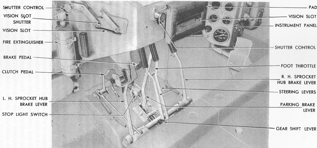
The driver's controls are labeled here. The steering levers applied the brakes to the differential and consequently steered the vehicle, while the sprocket hub brake levers operated the mechanical brakes found in the sprocket hubs and were to augment the foot brake pedal (which controlled these same brakes) when coming to a stop. These could be used to steer the machine in an emergency or upon failure of the differential brakes. The parking brake lever simply held the hub brakes tight after they were actuated by the foot pedal or levers. (Picture from TM 9-746 Universal Carrier T16.)
British universal carriers featured a steering wheel that went along with the track bending system found on those vehicles, but the T16 used a more conventional controlled differential to steer. The gearshift lever is in reverse in this picture. First gear was at the right rear, second at the forward right, third at the left rear, and fourth at the forward left.
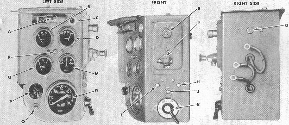
The instrument panel is labeled here. A. Instrument panel light. B. Engine oil pressure gage. C. Utility socket. D. Engine temperature gage. E. Headlamp beam selector button. F. Light switch. G. Generator circuit breaker reset button. H. Circuit breaker reset button for lights. J. Starter button. K. Ignition switch. L. Circuit breaker reset button for siren. M. Ammeter. N. Speedometer. O. Siren switch. P. Fuel gage tank selector switch. Q. Fuel level gage. R. Circuit breaker reset button for instrument. (Picture from TM 9-746 Universal Carrier T16.)

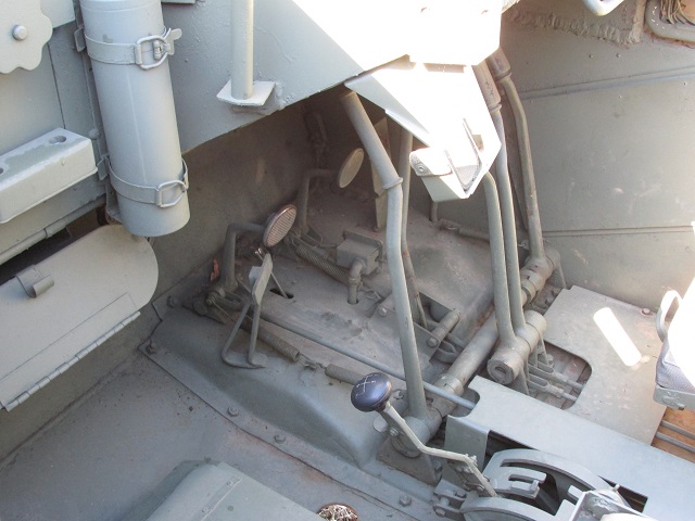
The driver's instrument panel is shown here installed in a carrier.
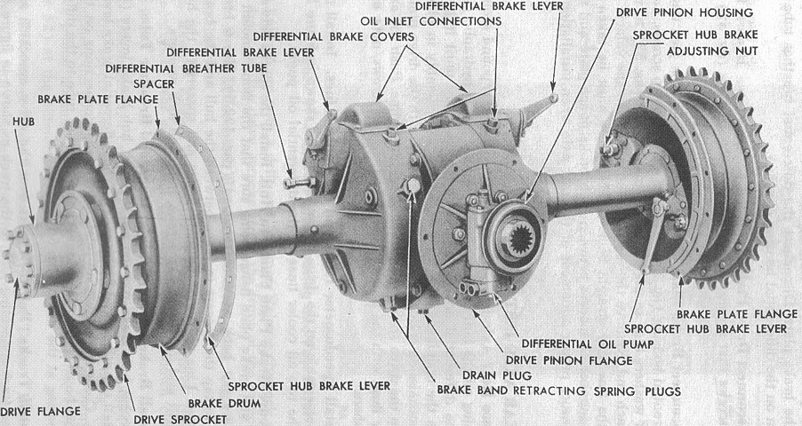
The rear axle was a full floating 1.57"- (3.99cm-) thick steel forging with a controlled differential. It was mounted to the hull rear at the drive pinion mounting flange and to the hull sides at the brake plate flanges. It had spiral bevel drive gears at a 5.83:1 ratio, and planetary differential gears. (Picture from TM 9-746 Universal Carrier T16.)
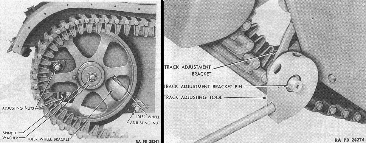
To adjust the track tension, the three idler wheel adjusting nuts were loosened, then the cam adjusting tool was installed on the adjusting bracket pin and turned in the appropriate direction. Proper tension was measured by .5" (1.3cm) sag at a point halfway between the support rollers from the bottom of a straightedge placed on the track between the support rollers. (Picture from TM 9-746 Universal Carrier T16.)
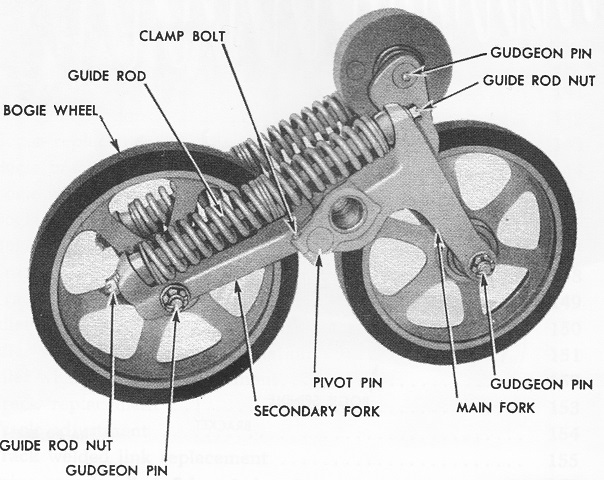
The bogies were also called suspensions in the contemporary nomenclature. (Picture from TM 9-746 Universal Carrier T16.)
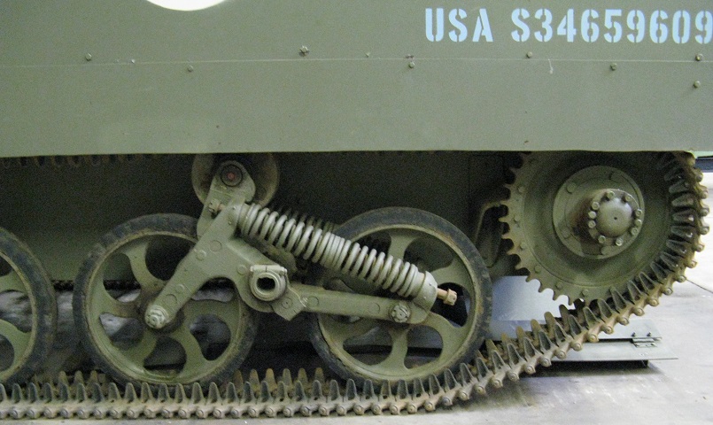
Details of the rear Horstmann-type suspension bogie and drive sprocket can be seen here.
