Heavy Tank M6.
The M6 heavy tank was nothing if not imposing, as this view illustrates. The smooth lines of the cast hull are apparent here. Hidden behind the 3" gun is the coaxial 37mm gun, which was similar to the main armament of the M2 medium tank produced three years previously. A .50cal machine gun is partially hidden by the open turret hatch, and two more .50cal MGs are mounted in a flexible mount in the right bow. Just behind the pistol port for the assistant driver is an antenna mount. (Picture from Development of Armored Vehicles, volume 1: Tanks.)
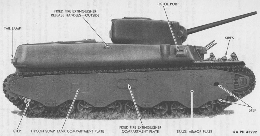
Features of the right side of the vehicle are labeled here. As seen on this tank, the flexible bow machine gun mount initially had the two .50cal machine guns offset in height with the inboard gun higher than the outboard. This was later changed so that both guns were side by side. (Picture from TM 9-721 Heavy Tanks M6 and M6A1.)
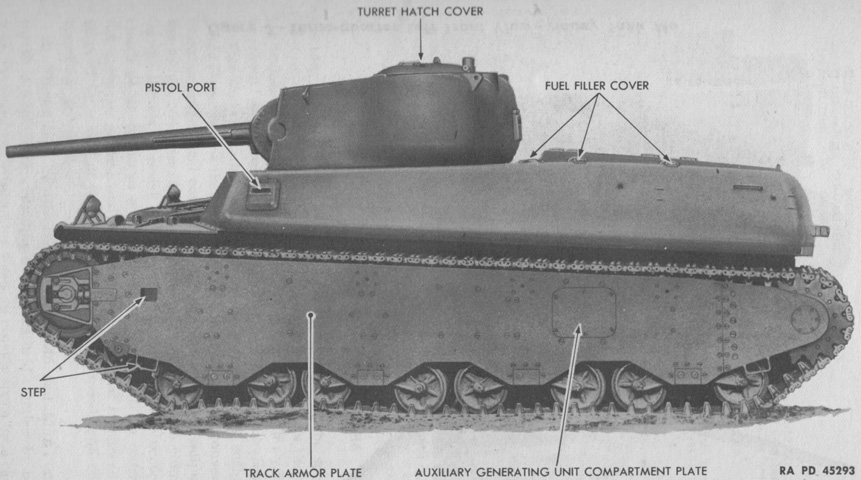
The tank is seen from the opposite side. Contrary to contemporary light and medium tanks, the drive sprockets were at the rear. When the the 3" gun was fully depressed, a fired projectile could strike the rear corners of the hull. Similarly, the depressed 3" gun would foul on the flexible bow .50cal machine guns if they were elevated. The tank commander was provided with a warning gage shaped like the tank with a pointer indicating the position of the main gun. Dangerous traversing areas were highlighted in red on this gage. The bow machine gun rotor was equipped with a warning device featuring a red light that flashed when the 3" gun was traversed above the mount. The bow machine gunner was responsible for depressing the machine guns out of the way. (Picture from TM 9-721 Heavy Tanks M6 and M6A1.)

The position of the tank's weapons are illustrated in this picture. No machine gun was mounted coaxially with the main armament, meaning that the TC had to expose himself to provide machine gun fire to the vehicle's sides or rear. (Picture from TM 9-323 3-inch Gun M7 Mounted in Combat Vehicles.)
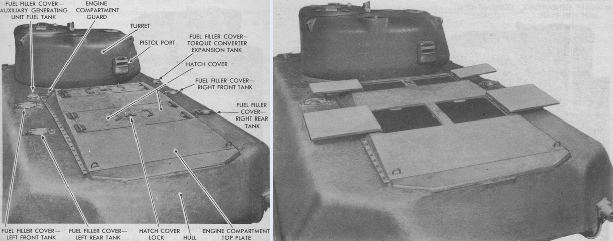
Access covers to the engine and transmission are secured on the left and open on the right. (Picture from TM 9-721 Heavy Tanks M6 and M6A1.)

The driver's controls are shown here, with the seat removed for clarity. The driver was provided with an elevation lever for the bow-mounted .30cal machine gun, and could fire the weapon from his position either by simultaneously pressing buttons atop both Hycon control levers or pulling on firing levers on both manual steering levers. The main gun switch and the gun safety switch on the instrument panel both had to be be activated for the firing switches and levers to work. The Hycon system provided hydraulic assistance to the driver to help steer the tank. The short Hycon control levers on top of the Hycon control box were normally used; the longer manual steering levers could be used when the Hycon system was inoperative. The M6 was driven without a clutch, but the transmission brake pedal needed to be depressed when changing gears to slow the converter turbine and transmission gears. (Picture from TM 9-721 Heavy Tanks M6 and M6A1.)

The driver's instrument panel is labeled. (Picture from TM 9-721 Heavy Tanks M6 and M6A1.)

The .30cal bow machine gun was situated in front of the assistant driver. The bow MG could be fired by the assistant driver in emergencies. (Picture from TM 9-721 Heavy Tanks M6 and M6A1.)
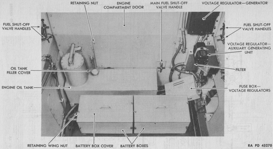
An overall view of the rear of the driving compartment is labeled. (Picture from TM 9-721 Heavy Tanks M6 and M6A1.)
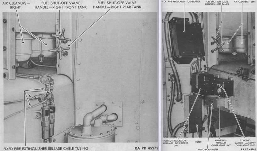
The right and left rear corners of the driving compartment are further detailed on the left and right, respectively. (Picture from TM 9-721 Heavy Tanks M6 and M6A1.)
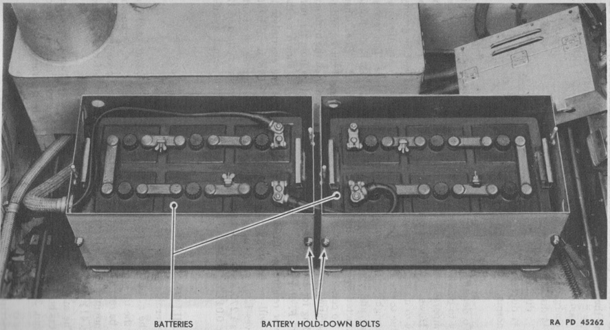
Two 12-volt storage batteries were connected in series to create a 24-volt electrical system. They were mounted in two boxes installed at the rear of the driving compartment. (Picture from TM 9-721 Heavy Tanks M6 and M6A1.)

The accessory side of the Wright G-200 is shown here. The engine displaced 1,823in³ (29,870cm³) with a bore of 6.125" (15.56cm) and a stroke of 6.875" (17.46cm). Compression ratio was 4.92:1, it weighed 1,350lb (612kg), and was 51.93" (131.9cm) long by 55.07" (139.9cm) in diameter. The cylinders were numbered clockwise starting with the top cylinder, and the firing order was 1-3-5-7-9-2-4-6-8. (Picture from TM 9-721 Heavy Tanks M6 and M6A1.)
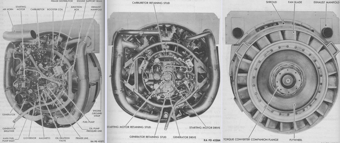
The accessory end of the engine is seen again in the left and center images, with the drive end of the engine on the right. (Picture from TM 9-721 Heavy Tanks M6 and M6A1.)
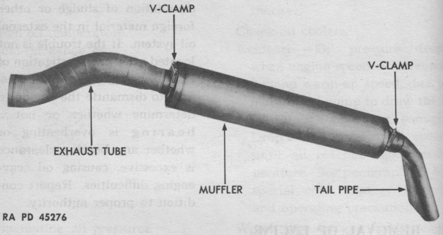
An exhaust tube, muffler, and tail pipe assembly has been removed from the vehicle. (Picture from TM 9-721 Heavy Tanks M6 and M6A1.)
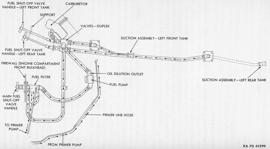
Gasoline for the main engine was carried in four fabric and synthetic rubber tanks, mounted horizontally with a pair in each sponson. A schematic of the fuel system is sketched here. (Picture from TM 9-721 Heavy Tanks M6 and M6A1.)

The auxiliary generator was a 2-cycle, 2-volt, single-cylinder, air-cooled, inverted type gasoline engine that ran at 3,500-3,600rpm. This powered a 30-volt, 1,500-watt generator. The unit was mounted in the left rear sponson, and could be accessed from outside through a removable plate in the left track armor or from inside the engine driving compartment. The control box and voltage regulator were in the left rear of the driving compartment. A 6gal (23L) fuel tank was accessed from the top of the hull, and ⅜ pint (180mL) of SAE 40, 50, or 60 engine lubricating oil was to be mixed with each gallon (3.8L) of gasoline. (Picture from TM 9-721 Heavy Tanks M6 and M6A1.)
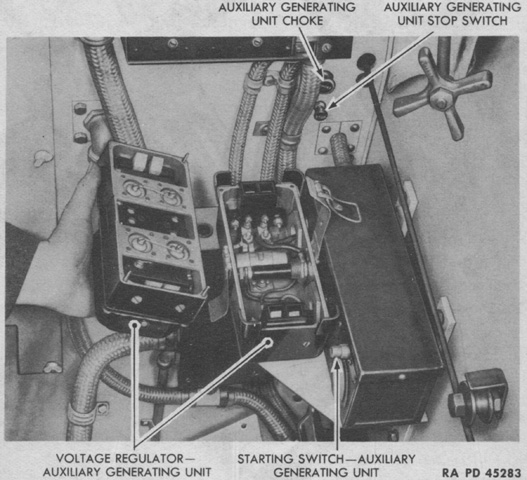
The controls for the auxiliary generator are show here along with the opened voltage regulator. (Picture from TM 9-721 Heavy Tanks M6 and M6A1.)
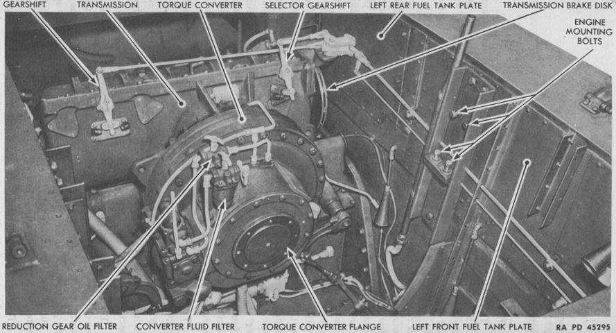
The torque converter was mounted directly behind the engine and connected to it via a flange-type flexible coupling, no propeller shaft being needed. A transmission with 2 forward speeds and 1 reverse was connected to the torque converter to solve limitations imposed by the converter's torque-speed ratio. The final drives were then connected to this transmission. (Picture from TM 9-721 Heavy Tanks M6 and M6A1.)
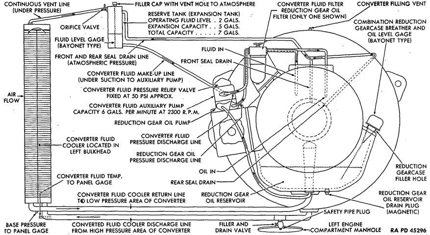
The torque converter fluid system is labeled in this schematic. The recommended fluid for the torque converter was ~35gal (~130L) of No. 1 grade diesel fuel. This fluid was circulated by a 20-blade centrifugal converter pump driven by the engine at ⅔ engine speed. The pump had a peripheral diameter of ~21" (~53cm). Fluid was discharged from the pump into the turbine, consisting of three stages of turbine blades and two stages of reaction blades. A reserve of ~2gal (~8L) of fluid was stored in an expansion tank found in the right sponson behind the air cleaners. (Picture from TM 9-721 Heavy Tanks M6 and M6A1.)

Certain maintenance operations could be performed with the torque converter installed in the tank, but advanced repair required the removal of the assembled torque converter, transmission, and final drive, since the converter could not be removed from the transmission until this entire assembly had first been dismounted from the tank. The torque converter, transmission, and final drive assembly is visible here. (Picture from TM 9-721 Heavy Tanks M6 and M6A1.)
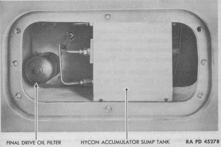
The Hycon hydraulic steering system housed its hydraulic fluid in a 10 ½" (26.7cm) spherical tank in the lower right rear sponson, accessible by removing a plate in the armored skirt or from within the engine compartment. A pump for the Hycon system was found on the right side of the torque converter. (Picture from TM 9-721 Heavy Tanks M6 and M6A1.)
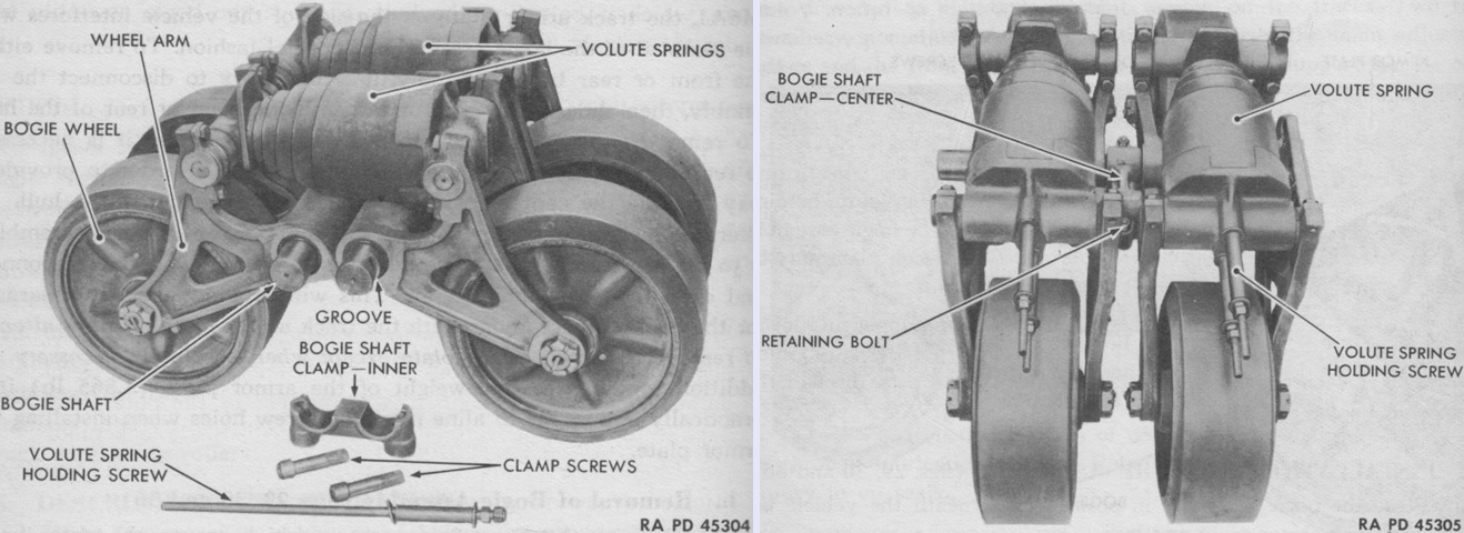
A suspension bogie is the subject of these pictures. Eight bogies, each with four wheels, were bolted to the hull and to the track armor plate. When inserted, the volute spring holding screws ran from one wheel arm to the other through the volute springs, and were used in preparation for removal of the springs, as seen on the right. (Picture from TM 9-721 Heavy Tanks M6 and M6A1.)
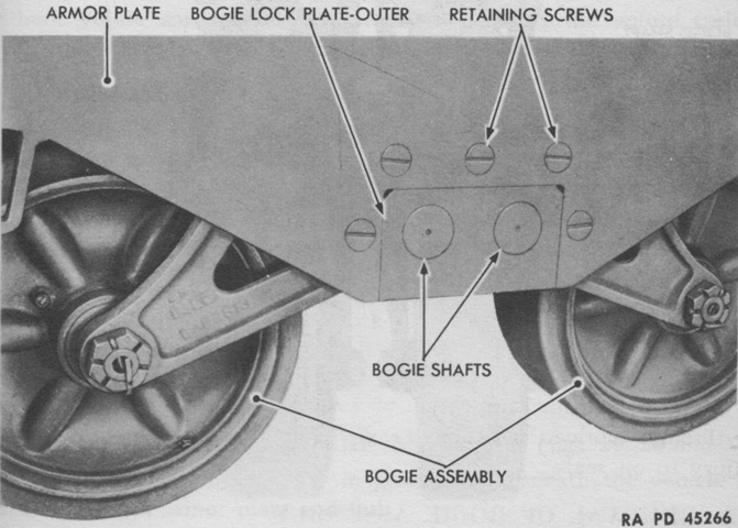
The track armor plate presented an obstacle when removing the bogies for replacement or repair; according to the technical manual this armor was to be dismounted only "when absolutely necessary," as its weight of 1,865lb (846.0kg) made it hard to handle and realigning the plate's retaining screw holes was "practically impossible." (Emphasis in original.) The front or rear bogies could be slid out from under the front or rear of the hull, however the center bogies required first removing one of the outer bogies so they too could roll out from under the tank, or else digging a pit under the affected center bogie. (Picture from TM 9-721 Heavy Tanks M6 and M6A1.)
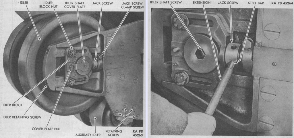
When correcting track tension, the dual front idlers required adjustment at both the outer and inner sides, as illustrated above. The two sides were to be turned in an alternating manner in order to prevent the idler wheel from becoming crooked. When finished, the distance between the idler block and jack screw clamp should have been the same on both the inner and outer sides. (Picture from TM 9-721 Heavy Tanks M6 and M6A1.)
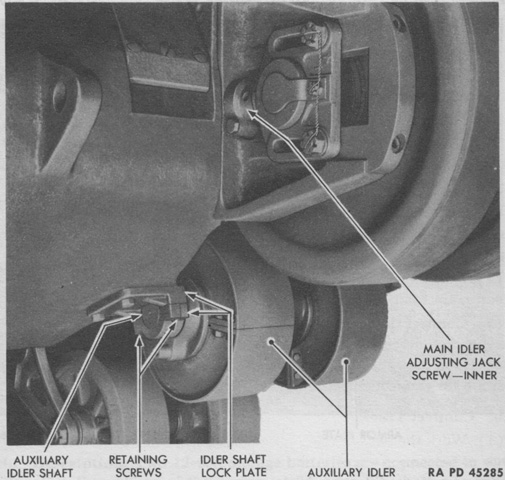
A nonadjustable auxiliary idler was mounted between each idler and front suspension bogie. The track would normally not contact this idler when on smooth terrain, but on rougher going it provided additional support for the track. (Picture from TM 9-721 Heavy Tanks M6 and M6A1.)
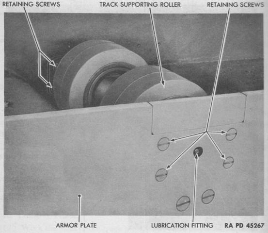
Each side of the tank featured four dual track supporting rollers that were bolted to the hull and the track armor plate. (Picture from TM 9-721 Heavy Tanks M6 and M6A1.)
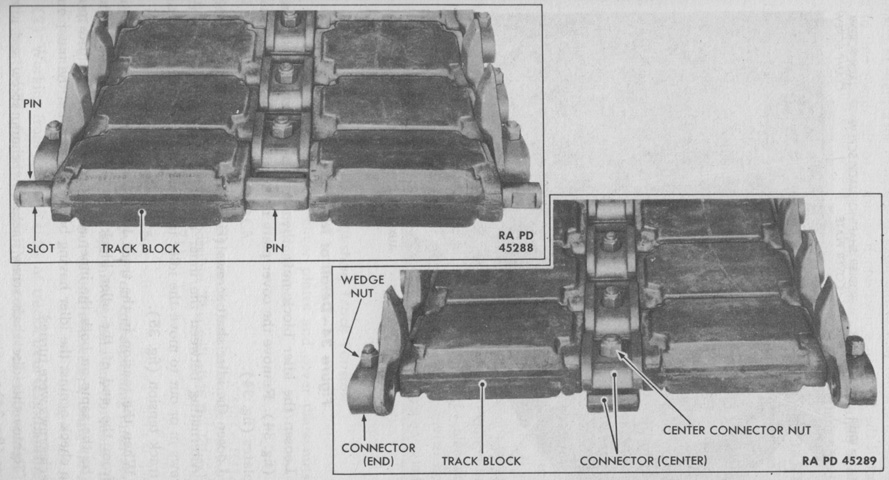
The tracks were double, consisting of two blocks held together by two parallel connecting pins. As seen above, the tracks on the M6 originally used outside guides, but thanks to the nature of the dual wheels, center guides were able to be installed during testing. The end track block is shown without the end and center connectors at the upper left, and with these connectors at the lower right. (Picture from TM 9-721 Heavy Tanks M6 and M6A1.)

The fire extinguishing system consisted of six 10lb (4.5kg) carbon dioxide cylinders that were routed to suffocate fires in the engine compartment. The cylinders were mounted halfway down the right sponson, and access was available via a removable plate in the track armor. In addition, a 4lb (2kg) portable extinguisher was mounted in the turret and in the drivers' compartment. (Picture from TM 9-721 Heavy Tanks M6 and M6A1.)
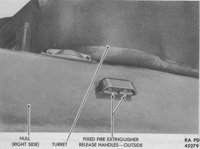
Two release handles for the fixed fire extinguisher system were available on the right side of the hull, seen above, and also at the assistant driver's position. Each handle in both locations actuated three cylinders, and the further the handle was pulled, the faster the gas was released. The second handle and group of three cylinders was to provide protection against another fire after the first actuation had been used. (Picture from TM 9-721 Heavy Tanks M6 and M6A1.)

The M6A1 differed principally in that it used a welded instead of cast hull. The sharp-angled joints of the hull plates are apparent. (Picture from Catalogue of Standard Ordnance Items, second edition 1944, volume I: Tank and Automotive.)

Although externally similar to the cast-hull M6, the T1E1 was driven by an electric drive system instead of a more conventional transmission. This vehicle is fitted with the center guide T31 tracks. These were made from a set of the outside guide tracks where the center guide replaced the center connector, and the outside guides were removed by flame cutting. Note the partially-open driver's visor on this tank. (Picture from Tank Data, vol. 1.)
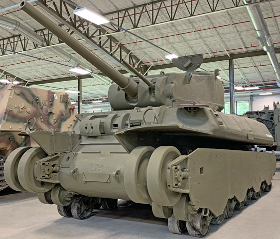
The tracks have been removed from this example, making the auxiliary idler wheels below the adjustable idlers easier to see. The 3" and 37mm guns certainly made for an impressive suite of weapons.
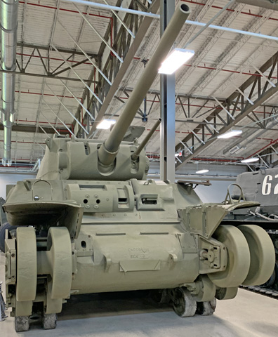
The opening for the fixed bow machine gun can be seen just inboard of the right-side idler wheel, while on the opposite side the opening is plugged. The driver and bow gunner both had direct vision devices in the front of the hull.
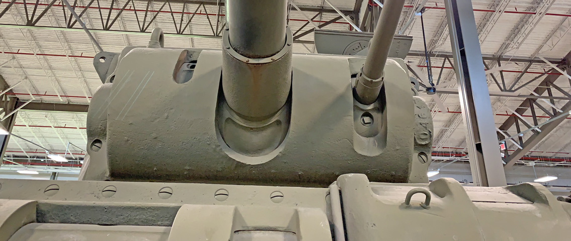
The gun shield had slots for elevation of the 3" and 37mm guns as well as the gunner's telescope.
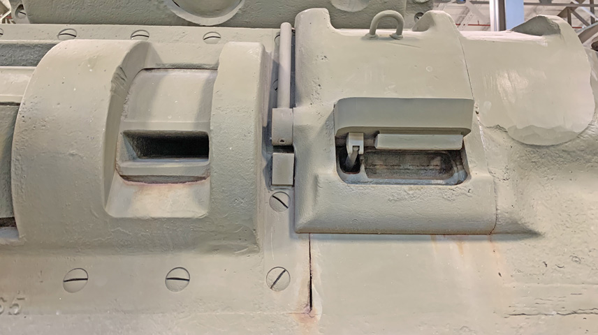
The bow gunner's and driver's direct vision devices are shown. The door to the front of the driver was recognized as a weak point in the hull armor, but a redesign to eliminate this feature was judged to need too much time to implement. The door was reduced in size from its original dimensions, however.
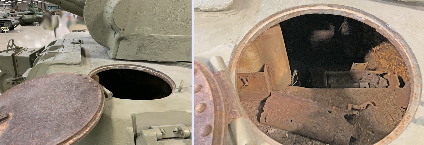
The driver's hatch is ajar on this machine, providing a glimpse at the thickness of the roof armor.
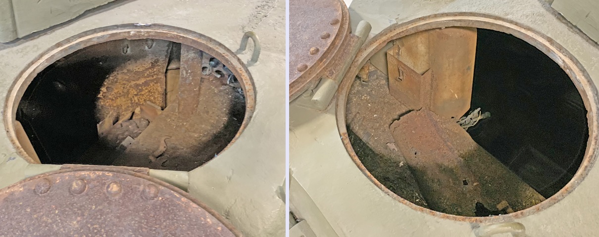
Further views into the rear and front, respectively, of the driver's compartment are above.
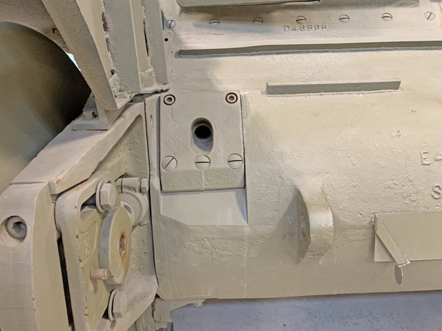
A closer look at the bow machine gun aperture is provided here. The driver could adjust and lock the elevation through a total of 15°, and normally fired this weapon electrically. The bow machine gunner could manually fire the gun in emergencies, however.
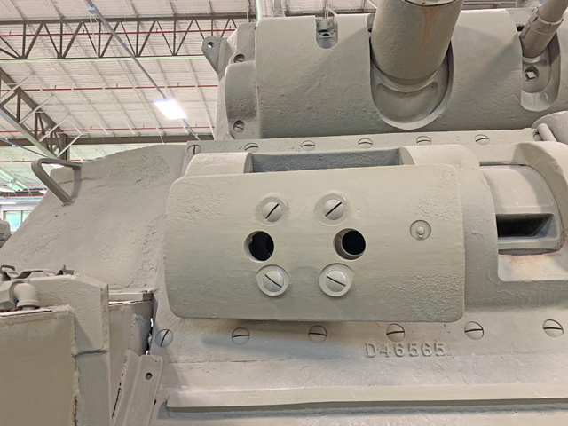
This tank has been equipped with the later .50cal machine gun mount with the guns mounted side-by-side. Earlier mounts had the guns offset in height, with the inner gun above the outer and a rod-type aiming device attached to the front of the gun shield.
A look behind the shield of the twin bow machine gun mount reveals the rotor and the aperture for the inner gun.
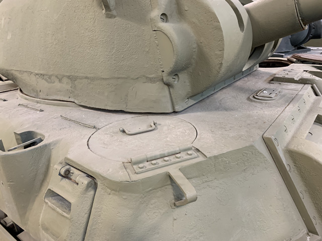
The bow gunner had a hatch in the front right corner of the hull roof, and a pistol port was installed to his right. Further inboard in the hull roof is the mount for a periscope attached to the twin machine gun mount via a parallel linkage so that the periscope elevated and depressed automatically with the machine guns.
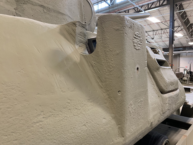
An antenna mount was on the hull side behind the bow gunner, protected by a stout amount of metal. The bow gunner's pistol port is just ahead.
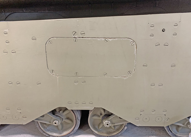
The armor plate protecting the suspension and lower side was a substantial piece. Access plates were secured for accessories like the fixed fire extinguisher system, visible here, and potential interference with suspension bogie removal is obvious.
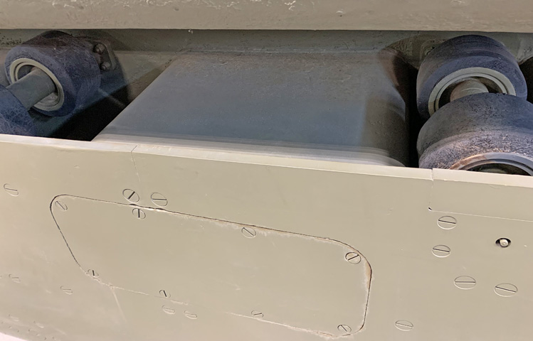
The housing for the fire extinguisher system connected to the hull behind the plate. The thickness of the armored skirt can be gleaned here.
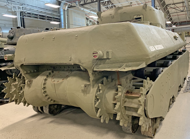
With the tracks removed, the three sprocket rings for each track are more easily visible. The series of track return rollers can also be seen.

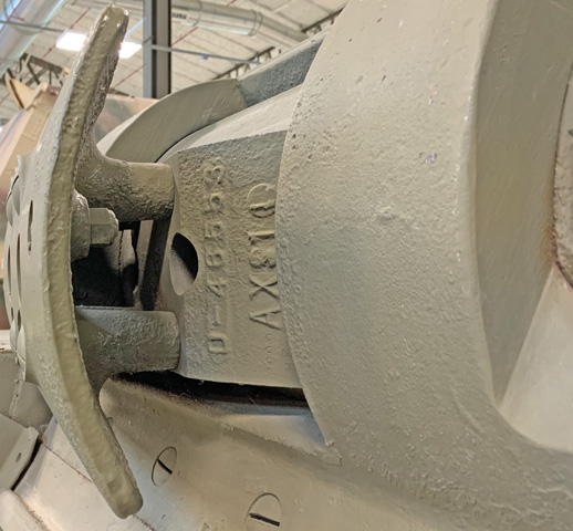
The final drive housing was a multi-piece casting that was secured to the lower hull and the engine exhaust overhang.
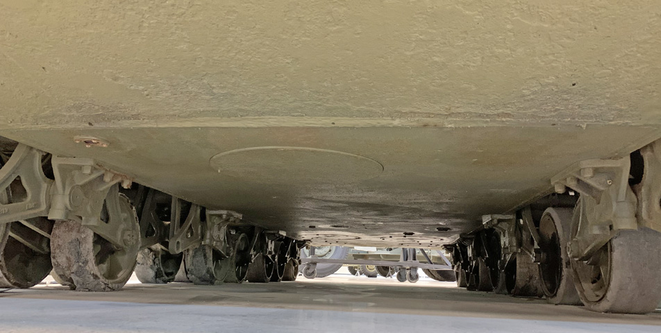
The underside of the front hull featured an escape hatch for the drivers.
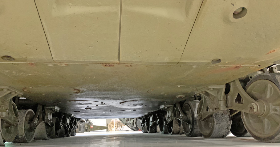
The rear hull floor had various access plates for the engine and transmission. Seams in the final drive housing are also plainly visible.
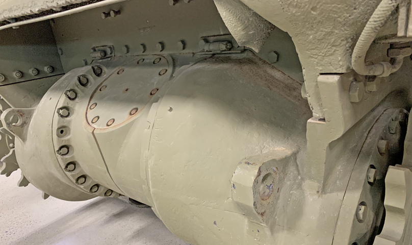
This image is closer look at the final drive housing. A deflector for the engine exhaust would typically sit atop the housing.
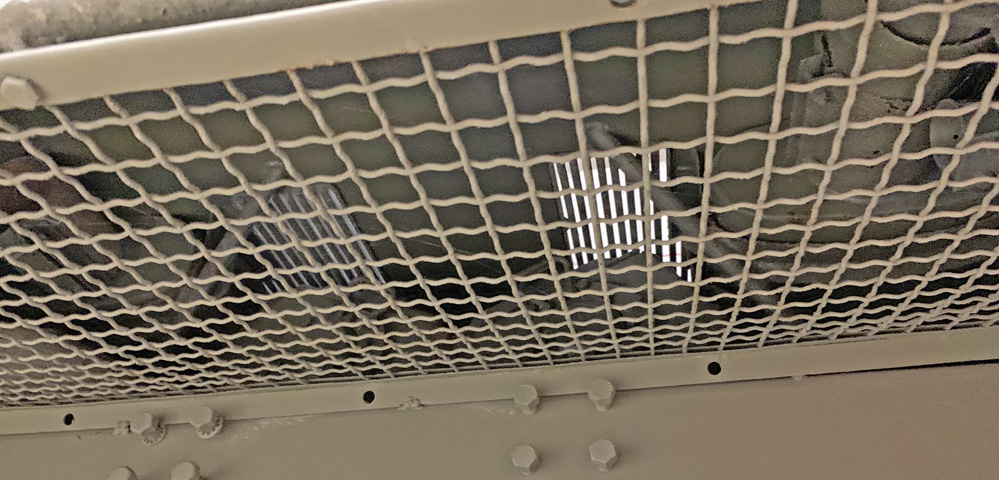
A view is provided looking above the final drive housing at the engine exhaust piping and mufflers. The downward-facing tip is absent from the left-side exhaust.
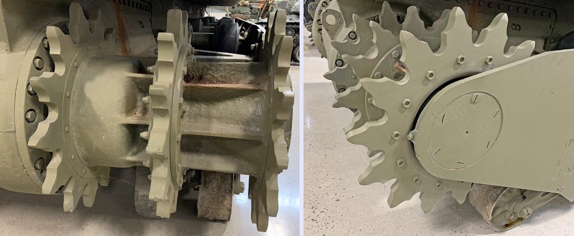
Three sprocket rings were used to grip the wide tracks at the outer ends as well as the center.
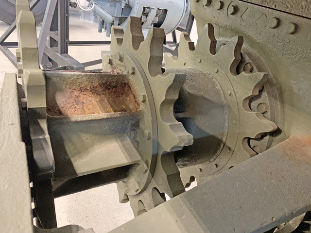
Further details of the drive sprocket assembly can be seen here.
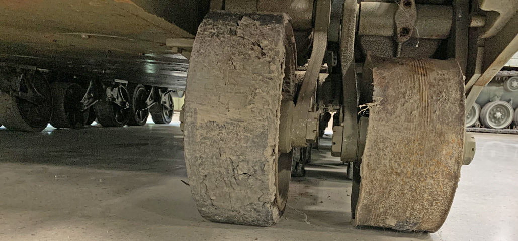
A suspension bogie is viewed from the rear. The wheel on the right has lost its rubber tire.
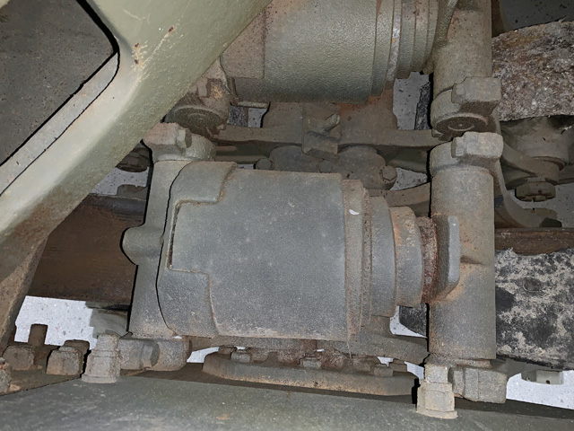
Seen from above, the large bogie volute springs would provide cushioning force. Replaceable plates absorbed wear between the wheel arms and spring levers.
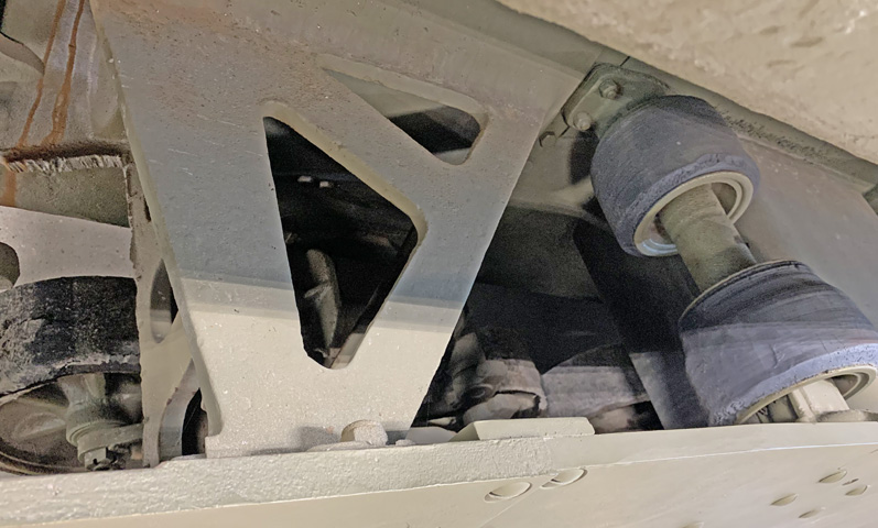
A broader view of the suspension also reveals a track support roller assembly and a support for the armored skirt plate.
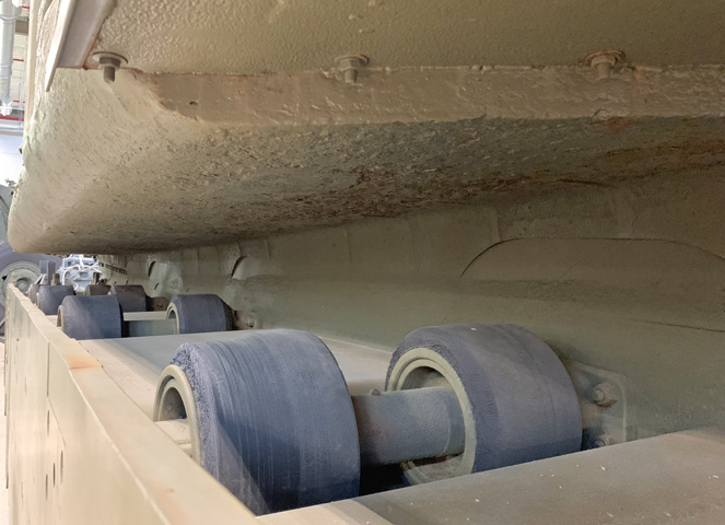
Track support rollers on the oppousite side of the hull are detailed here.
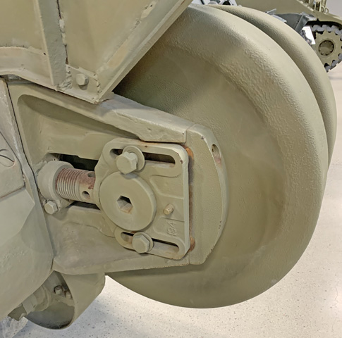
The inner left idler wheel adjustment mechanism is shown, which needed to be adjusted in an alternating fashion with the outside mechanism in order to keep the idler wheel straight.

The adjustable idler assembly on the left can be compared with the nonadjustable auxiliary idler on the right.
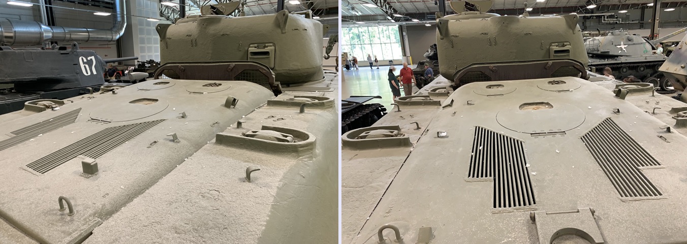
The electric drive transmission in the T1E1 necessitated a redesign of the rear deck, with additional cooling vents and different access panels.
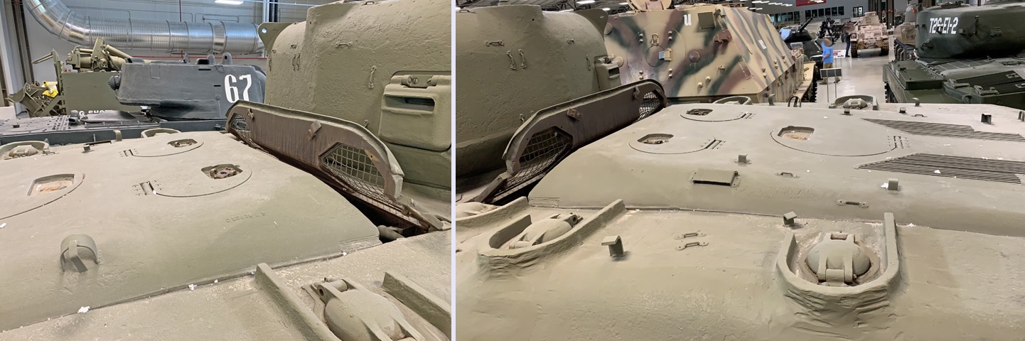
Further details of the revised rear deck can be seen here.
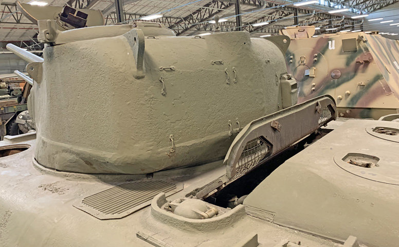
In addition to the ventilating openings in the deck casting, smaller openings were made in the hull at each rear corner of the turret.
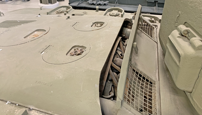
The engine was mounted at the front of the rear compartment, with the electric drive components to the rear.
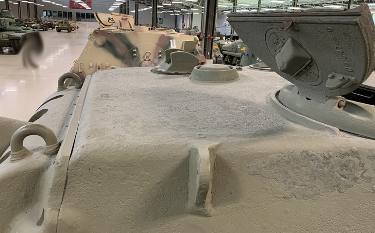
The turret roof is detailed in this image. In contrast to most American tanks, the commander was on the left side. A round ventilator and mount for the gunner's sighting periscope are visible on the opposite side of the roof.
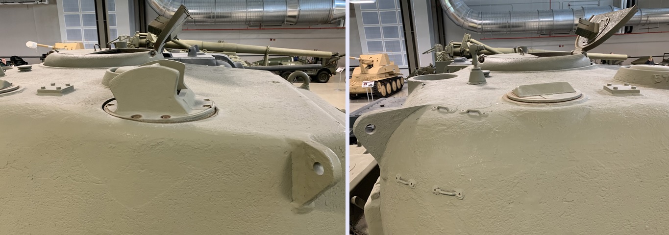
The front and rear of the turret roof right side are above at the left and right, respectively. Behind the gunner's sighting periscope was a rotatable periscope mount. A mount for a spotlight can be seen near the rear of the turret roof, and another inset antenna mount is at the extreme rear of the turret roof.
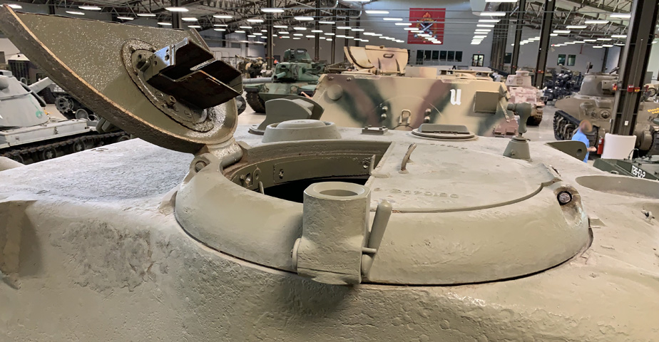
The commander had a rotating split circular hatch similar to that found on the medium tank. A machine gun socket is in the foreground, and a periscope mount can be seen in the open hatch door.
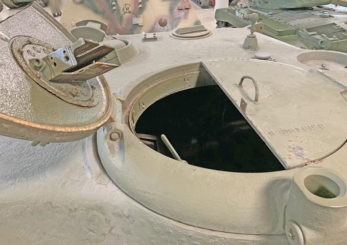
A steeper angle of the commander's hatch is provided here, with the empty spotlight mount above and bowl for an antenna to the upper right rear.