


| M42B1: General | |||
| Date of first acceptance | November 1944 | Total acceptances | 151 |
| Manufacturer | M.W Kellogg Co. | Crew |
|
| M42B1: Dimensions | |||
| Height over turret hatch | 108" 274cm |
Length without gun, without sandshields | 230" 584cm |
| Gun overhang forward | 0" | Width without sandshields | 103" 262cm |
| Tread | 83" 211cm |
Turret ring diameter | 69" 175cm |
| M42B1: Armament | ||||
| Type | Mount | Ammunition | Traverse | Elevation |
| Mechanized Flame Thrower Gun M5-4 | Turret | 270gal effective discharge capacity 1,020L effective discharge capacity |
360° (manual and hydraulic) |
+25° to -12° (manual) |
| .50cal M2HB MG | Flexible in turret AA mount | 330 rounds | 360° (manual) |
Manual |
| .30cal M1919A4 MG | Coaxial to flame gun | 4,000 rounds | 360° (manual and hydraulic) |
+25° to -12° (manual) |
| .30cal M1919A4 MG | Ball mount in right bow | 20° left, 25° right (manual) |
+20° to -10° (manual) |
|
| Aiming equipment | ||||
| Periscope M12 and telescope M70F for gunner | ||||
| M42B1: Armor | ||
| Assembly | ||
| Welding | ||
| Hull | ||
| Upper cast, lower rolled and cast homogeneous steel | ||
| Location | Thickness | Angle from vertical |
| Upper front | 2.0" 5.1cm |
37° to 55° |
| Lower front | 2.0" 5.1cm |
0° to 45° |
| Sides | 1.5" 3.8cm |
0° |
| Rear | 1.5" 3.8cm |
0° to 10° |
| Top | .75" to .5" 1.9cm to 1.3cm |
83° to 90° |
| Front floor | 1.0" 2.5cm |
90° |
| Rear floor | 0.5" 1.3cm |
90° |
| Turret | ||
| Cast homogeneous steel | ||
| Location | Thickness | Angle from vertical |
| Turret shield | 3.0" 7.6cm |
0° |
| Front | 3.0" 7.6cm |
30° |
| Sides | 2.0" 5.1cm |
5° |
| Rear | 2.0" 5.1cm |
0° |
| Top | 1.0" 2.5cm |
90° |
| M42B1: Automotive | |||||
| Engine | Continental R975 C4; 9 cylinder, 4 cycle, static radial, supercharged gasoline | ||||
| Horsepower | Net: 400@2,400rpm Gross: 460@2,400rpm |
Torque | Net: 940 ft-lb@1,700rpm Gross: 1,025 ft-lb@1,800rpm |
Fuel capacity | 175gal 662L |
| Transmission | Synchromesh, 5 speeds forward, 1 reverse | ||||
| Steering | Controlled differential, steering levers | ||||
| Brakes | Mechanical, external contracting | ||||
| M42B1: Suspension | ||
| Type | Road wheels | Track return rollers |
| Vertical volute spring | 3 bogies/track; 2 wheels/bogie |
1 at rear of each bogie |
| Drive sprockets | Idlers | Shock absorbers | 13-tooth front drive | Adjustable at rear of track | None |
| M42B1: Track | |||||||
| T48 | |||||||
| Outside guide, double pin, chevron, rubber | |||||||
| Width | 16.56" 42.06cm |
Pitch | 6" 15cm |
Shoes/track | 79 | Ground contact length | 147" 373cm |
| T49 | |||||||
| Outside guide, double pin, parallel bar, steel | |||||||
| Width | 16.56" 42.06cm |
Pitch | 6" 15cm |
Shoes/track | 79 | Ground contact length | 147" 373cm |
| T51 | |||||||
| Outside guide, double pin, smooth, rubber | |||||||
| Width | 16.56" 42.06cm |
Pitch | 6" 15cm |
Shoes/track | 79 | Ground contact length | 147" 373cm |
| T54E1 | |||||||
| Outside guide, double pin, chevron, steel | |||||||
| Width | 16.56" 42.06cm |
Pitch | 6" 15cm |
Shoes/track | 79 | Ground contact length | 147" 373cm |
| M42B1: Performance | |||
| Max level road speed | 21mph sustained 24mph dash 34kph sustained 39kph dash |
Max trench | 90" 230cm |
| Max grade | 60% | Max vertical obstacle | 24" 61cm |
| Min turning diameter | 62' 19m |
Max fording depth | 40" 100cm |
| Cruising range | ~120mi, roads ~190km, roads |
||
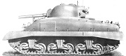
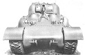
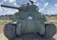
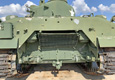
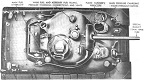
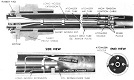
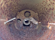
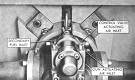
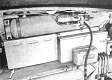
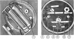
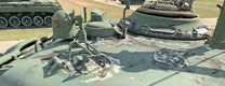
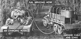
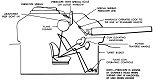
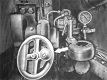
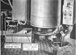
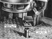
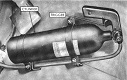
The M42B1 and M42B3 were the first US flame thrower tanks to receive their own designation, although this was not approved until 20 December 1945. M42B1 was assigned to medium tanks M4A1 armed with the mechanized flame thrower E12-7R1, while M42B3 referred to M4A3s with this weapon. The flame thrower was standardized as the M5-4. The design replaced the 75mm gun with the flame thrower, which consisted of the M5 fuel and pressure unit installed in the hull and turret basket, and the M4 mechanized flame thrower gun. The flame thrower gun was ensconced in a dummy 75mm gun tube made of .5" (1.3cm) face-hardened armor so that the flame tank's identity could not be detected until it started firing. Modifications made for the conversion included rebuilding, rewiring, and shortening the turret basket by 7" (18cm). Turret stowage consisted of main and secondary fuel containers, an atomizer fuel container, and an auxiliary pressure container in the area formerly occupied by the loader. The 75mm gun M3, gun mount M34, and counterweight were replaced by the mount for the flame gun, which included the dummy gun tube, rotor mount, and turret shield counterweight. The batteries were moved from the floor to the left sponson, the hull was rewired, and if the main generator was originally found on the hull floor by the driver, it was replaced by a standard generator over the drive shaft. The main fuel system had three containers piped in series, with two in the hull and one in the turret. These stowed 291 gross gallons (1,100 gross L), with a maximum fuel capacity of 275gal (1,040L) to allow for expansion space or void, yielding 270gal (1,020L) of effective discharge capacity. This effective discharge capacity was equivalent to 1,700lb (770kg) of thickened fuel. The operating pressure was 360-390psi (25-27kg/cm²), while operating pressure at the nozzle was 325-350psi (22.8-24.6kg/cm²). The discharge rate with a .5" (1.3cm) nozzle was 2.2gal/s (8.3L/s) at a 195ft/s (59.4m/s) flow rate, or 4.4gal/s (17L/s) at 205ft/s (62.8m/s) with a .75" (1.9cm) nozzle. Total firing time was 125 seconds with the smaller nozzle and 63 seconds with the larger. The secondary fuel system contained 12.5gal (47.3L) of motor fuel, operated at 520-540psi (37-38kg/cm²), and flowed at 300cm³/s.
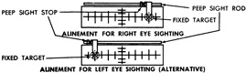
Twenty-two early M42B1s (serial numbers 4,800-1,001 to 4,800-1,020, and 5,200-1,021 and 5,200-1,022) could stow around 10gal (40L) more effective main fuel capacity and 2.5gal (9.5L) more secondary fuel capacity. Also, this cohort did not receive special flame gun sighting devices; their turret basket floor rims were not cut to provide easier access to the engine air strainers and engine lubricant filling pipe; in some, the turret roof well for flame fuel filling wasn't completely sealed from the turret interior; the dummy gun tube was homogeneous armor instead of face-hardened armor; and the numbering of electrical wires and cables was different from later machines.
