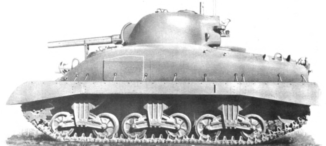
Flame Thrower Tank M42B1.
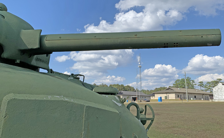
The dummy gun tube goes far in hiding the identity of the mechanized flame thrower gun M4-5, although the gap for removing the upper part of the tube can just be seen. Note the fenders on this tank: they are extended to cover the -E9 spaced out suspension that allowed extended end connectors on the inboard side of the track. (Picture from TM 3-360 Flame Thrower, Mechanized, E12-7R1.)
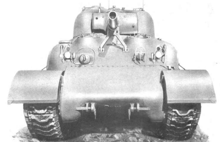
Viewing down the gun tube reveals the flame gun hardware instead of a rifled bore. All the machine guns normally found on the medium tank were retained. Note the extended end connectors on both sides of the tracks. (Picture from TM 3-360 Flame Thrower, Mechanized, E12-7R1.)
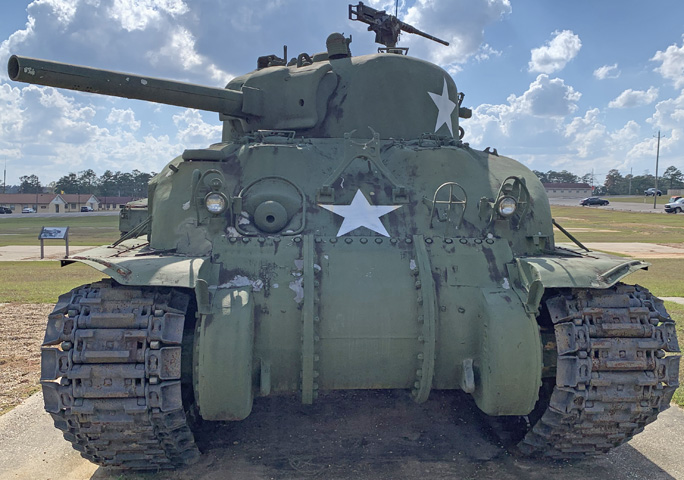
The spaced-out suspension on this tank is easily seen with the sandshields absent. It has been fitted with a three-piece final drive and differential housing.
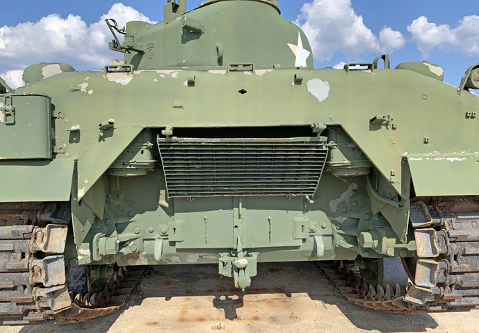
An exhaust deflector is present between the engine air cleaners, and extra armor pieces have been welded to the hull rear to increase protection for the air cleaners. An armored box for a first aid kit is mounted above the left fender.
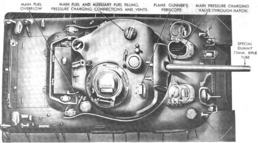
No loader was present, and his area was taken up by the fuel container and pressure equipment. In place of his periscope was a well sheltering the flame fuel refilling connections. Note that the cap to the well still featured a brush guard similar to that of an actual periscope. (Picture from TM 3-360 Flame Thrower, Mechanized, E12-7R1.)
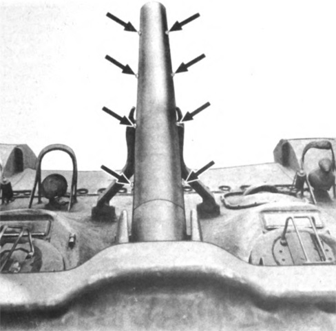
The dummy gun tube was was fabricated from .5" (1.3cm) face-hardened armor plate. The arrows are pointing at the eight special stainless steel screws that attached the removable upper portion. (Picture from TM 3-360 Flame Thrower, Mechanized, E12-7R1.)
The upper half of the dummy tube is visible here, along with screws securing it to the lower portion. Holes are present in the bottom for air to enter to enhance combustion.
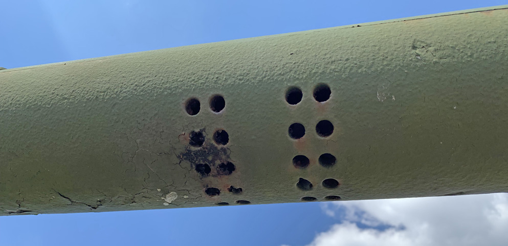
A closer view of the holes in the lower half of the dummy gun tube is provided.
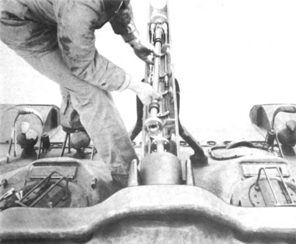
With the dummy gun tube open, maintenance could be performed on the flame gun, or the different-sized nozzle could be installed, which is being depicted in this image. (Picture from TM 3-360 Flame Thrower, Mechanized, E12-7R1.)
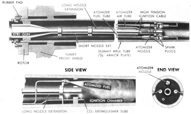
The forward 11" (28cm) portion of the tube was the ignition chamber, containing the spark plugs, ground electrodes, carbon dioxide extinguisher outlet, and the flame gun nozzle outlet. A .75"- (1.9cm-) thick armor plate separated the ignition chamber from the rest of the gun tube; the nozzle emerged from the center of this plate, and the spark plugs were screwed into holes on each side of the nozzle. The atomized spray of fuel and secondary air was injected from a hole above the nozzle. The atomizer had a flow rate of 1.5-3cm³/s. (Picture from TM 3-360 Flame Thrower, Mechanized, E12-7R1.)
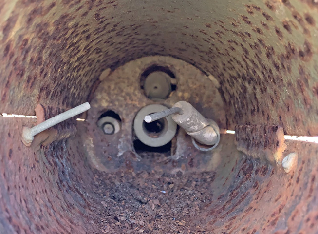
A view into the flame gun tube reveals the atomizer nozzle at 12:00, spark plug remnants at 3:00 and 9:00, and the flame gun nozzle would emerge from the center. The atomizer nozzle was to be positioned ¾" (1.9cm) behind the top hole in the ballistic plate in order for the jet action of the fuel spray to suck in sufficient air.
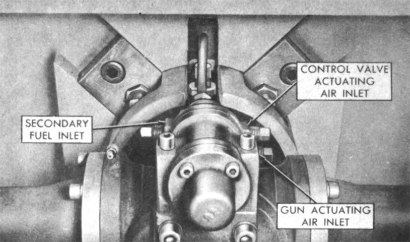
A tapered collar on the breech end of the flame gun mated to a tapered seat in the turret shield, and four hold-down lugs and locking bolts secured the flame gun from the inside of the turret. (Picture from TM 3-360 Flame Thrower, Mechanized, E12-7R1.)
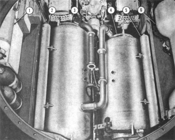
The main fuel and pressure containers in the hull are shown here with the turret removed. Two fuel containers were mounted in the hull, with the third in the turret. All three were connected in series, so fuel flowed from one into another. Two compressed air or compressed nitrogen pressure containers were mounted in the sponsons, and these were connected to four smaller containers mounted around the hull fuel containers; total capacity of the hull pressure containers was 10ft³ (.28m³). The containers were assigned names for identification: 1. Main pressure container AH-2. 2. Main pressure container AH-6. 3. Hull main fuel container FH-2. 4. Hull main fuel container FH-1. 5. Main pressure container AH-4. 6. Main pressure container AH-1. (Picture from TM 3-360 Flame Thrower, Mechanized, E12-7R1.)
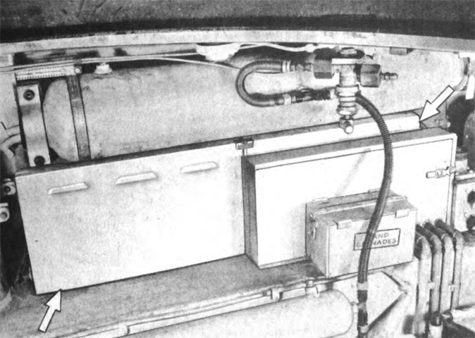
With the hull fuel and pressure containers taking up the space under the turret, it was necessary to relocate the tank's batteries to the left sponson. The battery box into which they were installed is under the main pressure container AH-2. (Picture from TM 3-360 Flame Thrower, Mechanized, E12-7R1.)
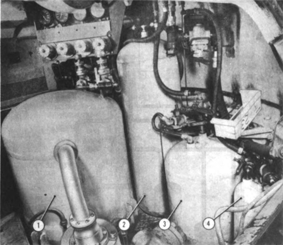
The secondary fuel system provided a coating of engine fuel or gasoline around the main fuel stream as it left the flame gun nozzle to ensure complete ignition during crosswinds or low ambient temperatures. Engine fuel from the basket atomizer fuel container was sent through the atomizer nozzle and was there ignited by the two spark plugs screwed into the ballistic plate at the rear of the ignition chamber. This produced a pilot flame that ignited the main fuel stream as it left the flame gun. The spark plugs were powered by the vehicle's 12-volt battery circuit. The turret pressure tank had a 2.6ft³ (.074m³) capacity, and the atomizer fuel container could hold 2gal (7.6L). 1. Turret main fuel container FB-1. 2. Basket auxiliary pressure container AAB-1. 3. Basket secondary fuel container SFB-1. 4. Basket atomizer fuel container ATB-1. (Picture from TM 3-360 Flame Thrower, Mechanized, E12-7R1.)
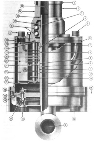
The tank's rotary joint was a special collector ring design that allowed electrical and interphone carriage as usual, but also contained a fuel channel to allow 360° traverse of the flame gun. The fuel channel connected to the left main hull fuel tank at the bottom and the basket main fuel container inlet at the top. The top connection of the joint was separated from the fuel channel and was held to it by ball bearings in a cylindrical grease housing. The top connection was clamped to and rotated with the turret basket fuel container, while the fuel channel tube remained stationary with the hull. For the following legend, (R) indicates rotation with turret basket, and (F) indicates a fixed orientation with the hull. 1. Outer flange face (R). 2. Mounting groove. 3. 2" (5.1cm) inner diameter stand pipe (F). 4. Insulating washer (F). 5. Cannon fitting electrical outlet to turret (R). 6. Main housing flange (R). 7. Locknut (F). 8. Insulating rings (F). 9. Slip ring (F). 10. Insulating ring (F). 11. Slip ring (F). 12. Insulating ring (F). 13. Grounding slip ring (F). 14. Turret basket floor level. 15. Cannon fitting electrical inlet from hull (F). 16. Main fuel inlet from hull containers. 17. Electrical terminal bolt (F). 18. Wired bolts. 19. Synthetic rubber grommet. 20. Oil chamber bottom plate (F). 21. Collector ring housing mounting plate (R). 22. Oil chamber housing (F). 23. 24-volt section. 24. Electrical shield plate (R). 25. Collector ring housing (R). 26. Slip rings (F). 27. 12-volt section. 28. Felt washer (R). 29. Wired bolts. 30. "O" rubber sealing ring (oil chamber seal). 31. Thrust bearings. 32. Lock ring (F). 33. "O" rubber sealing ring (main fuel pressure seal). 34. Bearing housing. 35. Main fuel channel to turret fuel container. (Picture from TM 3-360 Flame Thrower, Mechanized, E12-7R1.)
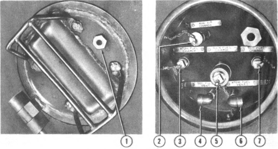
The well that protected the connections for the filling and charging hoses is shown here, closed and open. The cap featured a faux periscope and brush guard. 1. Outlet hole in cover bolt. 2. Auxiliary air charging connection. 3. Atomizer fuel filling cap. 4. Secondary fuel container vent. 5. Main fuel filling coupling. 6. Atomizer fuel container vent. 7. Secondary fuel filling cap. (Picture from TM 3-360 Flame Thrower, Mechanized, E12-7R1.)
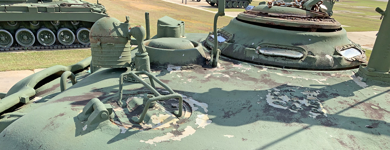
The well cap on this tank is of a slightly different design, with a an aperture in the fake periscope cover. In the background can be seen a spotlight, ventilator blower, the gunner's periscope housing, the commander's cupola and vane sight, and the .50cal machine gun mount and barrel travel lock.
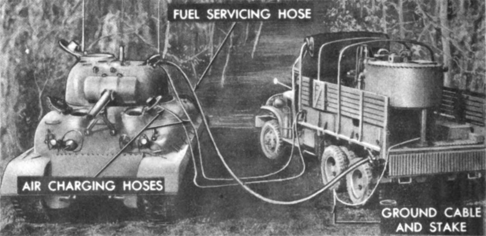
The tank is shown here being rearmed by an E8R1 mechanized flame thrower service unit. (Picture from TM 3-360 Flame Thrower, Mechanized, E12-7R1.)
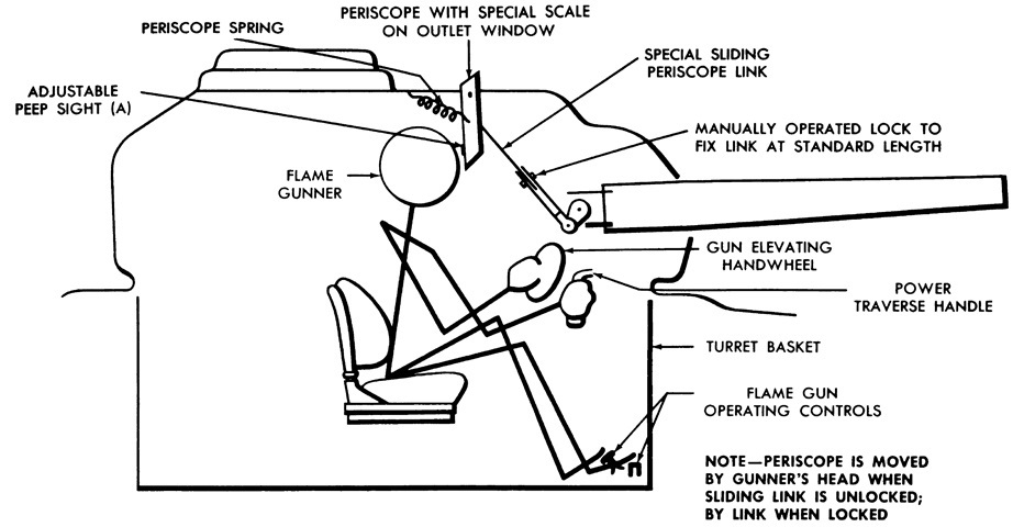
The gunner was provided with a periscope linked to the flame gun. Horizontal and vertical sighting lines were inscribed on the outer periscope window, and the inner window featured a horizontally-adjustable peep sight. The peep sight allowed the flame gun to be "boresighted" to a given horizontal reference line on the outside periscope window. (Picture from TM 3-360 Flame Thrower, Mechanized, E12-7R1.)
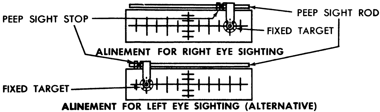
A schematic for adjusting the peep sight to the gunner's preferred eye is sketched above. The gunner would aim at a target 75 yards (69m), or other anticipated average range, from the tank and fire a short burst of fuel thickened to the same consistency as that to be employed on the upcoming mission. Once a direct hit was obtained, the periscope's sliding rod was rotated until the target appeared on the horizontal sight scale line, and the peep sight was moved across until the target lined up with one of the vertical scale lines. Lock nuts were then used to secure the periscope rod and the peep sight stop. When aiming at a target after this procedure, the target could be aligned with the intersection of the vertical and horizontal range scale lines when viewed through the peep sight. Adjustments for range could be estimated based on the horizontal reference lines, and for crosswinds, etc., based on the deflection of the fuel rod. (Picture from TM 3-360 Flame Thrower, Mechanized, E12-7R1.)
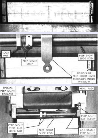
Three views of the gunner's periscope are provided here. At the top, the inscribed sight scale lines are just visible. In the center, the peep sight is in view, and its stop and lock nut are at the left. At the bottom, the peep sight could be moved to the extreme right and flipped upward out of the way. Since the peep sight stop was locked into position, the peep sight would still be zeroed when flipped down and slid to the left. If the periscope sliding link was unlocked, the gunner could push against the periscope with his head in order to change its field of view. A spring returned the periscope to its original position when pressure was released. The gunner used a standard telescope M70F for coaxial machine gun fire. (Picture from TM 3-360 Flame Thrower, Mechanized, E12-7R1.)
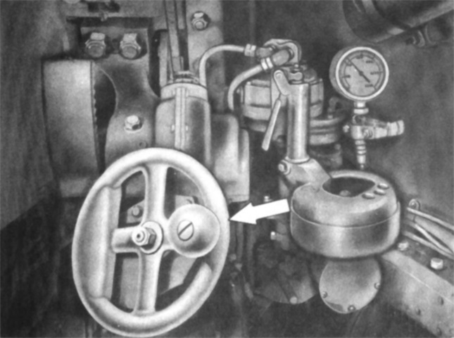
The elevation handwheel elevated the flame gun and coaxial machine gun when rotated counterclockwise, and depression was achieved with clockwise rotation. A special elevating gear adaptor was added to increase the elevation speed to twice that of a normal medium tank. Visible in the background is the auxiliary air pressure gage. (Picture from TM 3-360 Flame Thrower, Mechanized, E12-7R1.)
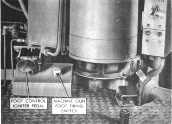
The foot control igniter pedal and coaxial machine gun foot firing switch were actuated by the gunner's left foot. The igniter pedal activated the spark plugs in the flame gun when it was pressed if the ignition safety switch was in the "ignition" position. As the spark plugs were activated, the pedal also released the atomized fuel-air mixture around the sparks, creating the ignition flame. On the right can be seen the turret traverse switch; on the top of that same box were the safety toggle switches for fuel firing, ignition, and the coaxial machine gun. Red signal lights on the front of the box indicated which safety switches were live. (Picture from TM 3-360 Flame Thrower, Mechanized, E12-7R1.)
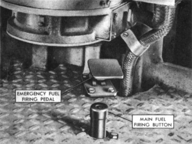
The gunner's right foot operated the main fuel firing button, which released both main fuel through the flame gun nozzle and secondary fuel surrounding the main fuel stream. The emergency fuel firing pedal could be used if the main fuel firing button's electrical circuit failed, instead discharging the flamethrower fuel mechanically. (Picture from TM 3-360 Flame Thrower, Mechanized, E12-7R1.)
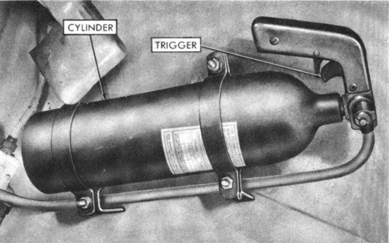
A 4lb (1.8kg) carbon dioxide fire extinguisher was mounted on the turret wall to the gunner's right, and it was piped to the flame gun. After firing the flame gun, this extinguisher was to be actuated for half a second to put out fires that might start at the gun muzzle. (Picture from TM 3-360 Flame Thrower, Mechanized, E12-7R1.)
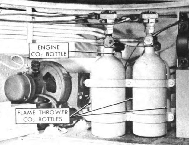
The fixed fire extinguisher cylinders were relocated from their normal position to the left sponson just ahead of the auxiliary generator. In addition to a single 10lb (4.5kg) CO2 cylinder routed to the engine compartment, three similar cylinders were routed to discharge into the hull. Separate remote control handles for both the engine compartment and hull cylinders were installed behind and above the driver (top handle for the hull and bottom for the engine) and on the hull near the left fuel tank filler (right handle for the hull and left for the engine). A 2lb (.9kg) CO2 portable extinguisher was stowed in a bracket in the turret. (Picture from TM 3-360 Flame Thrower, Mechanized, E12-7R1.)
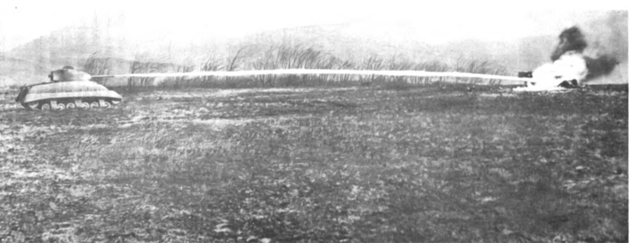
A thickened fuel load is being discharged in this image. To fire, the gunner pressed and held the foot control igniter pedal with his left foot, then pushed the main fuel firing button with his right foot, releasing both simultaneously to cease or interrupt firing. The fire extinguisher for the muzzle was then to be actuated to extinguish any lingering flame. With no wind, the tank could place the center of its ground deposit of 8% thickener fuel 105 yards (90.0m) away at 20° elevation with the .5" (1.3cm) nozzle, or 140 yards (128m) with the .75" (1.9cm) nozzle at the same elevation. (Picture from TM 3-360 Flame Thrower, Mechanized, E12-7R1.)
