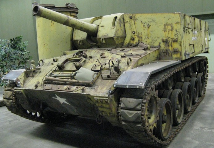
105mm Howitzer Motor Carriage M37 at the American Armoured Foundation Tank Museum.
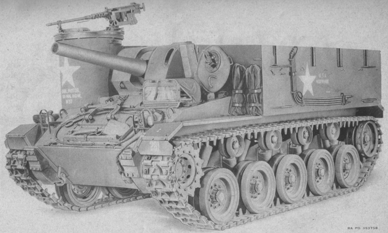
The M37 is a very similar design to the 105mm HMC M7. The lighter-weight chassis of the M24 tank was expected to be more useful and easier to handle than the HMCs based on medium tanks. The M4 howitzer was ballistically identical to the M2A1 howitzer found in the M7, but had been designed for use in the Sherman tank. The lengthened Chaffee chassis of the M37 featured more distance between the road wheels. The driver's hatch remained in the usual place, and the steering assembly access hatch remained from the M24 tank as well. Just behind the driver's hatch is the external fire extinguisher control handle, and stowage for the machine gun tripod is visible on the front plate of the fighting compartment to the driver's left. Top cover brackets run along the top of the side armor, and stowage for top cover bows is visible on each side of the fighting compartment.
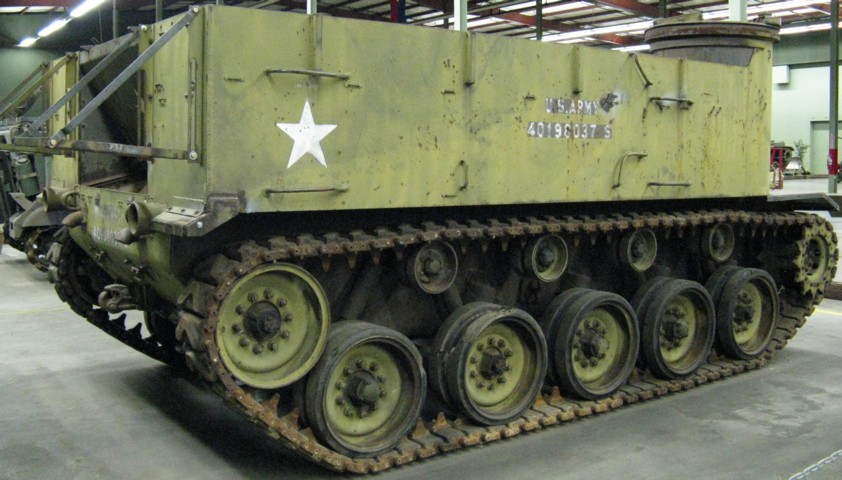
Horizontal grab handles are welded to the side of the superstructure, and the rear stowage racks are folded down on this vehicle. A fourth track return roller was necessary with the lengthened chassis.
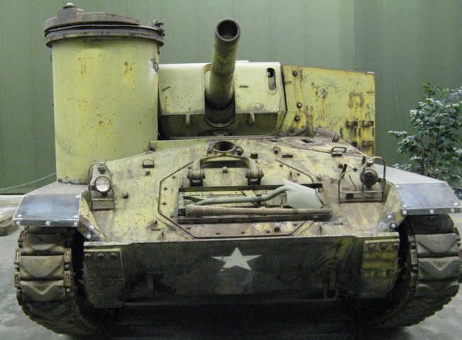
The howitzer travel lock is folded down onto the vehicle's front plate, and the machine gun mount dominates the vehicle's right front corner.
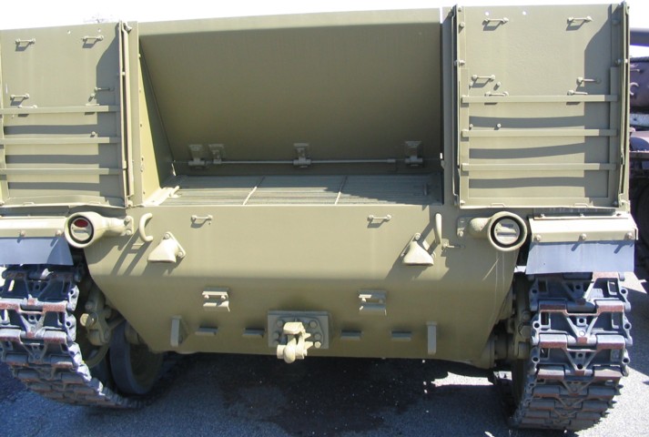
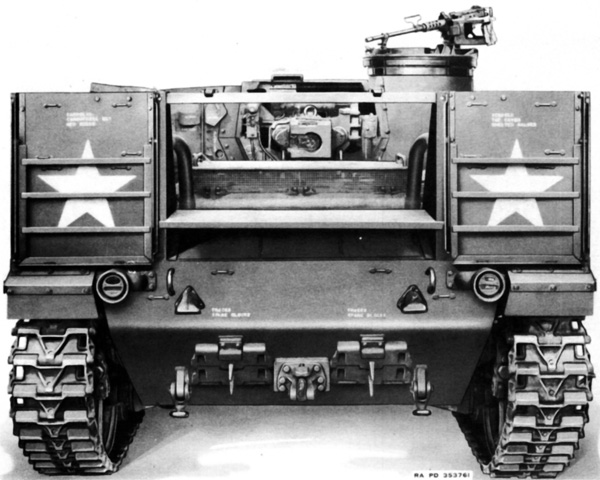
The rear stowage racks are secured on this vehicle. The hinge for the rear door can be seen. When swung down to the open position, this door could also be used as a loading platform. Below the door is the air outlet grille of the engine compartment. Spare track block stowage is on each side of the towing pintle, and the engine exhaust outlets are visible just inboard of the lifting eyes on the hull rear.
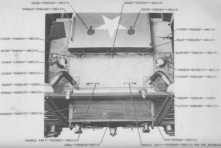
The rear rear of the vehicle is highlighted from above. (Picture from ORD 9 SNL G-236 (Includes SNL G-238).)
The rear door has been lowered in this picture. (Picture from ORD 9 SNL G-236 (Includes SNL G-238).)
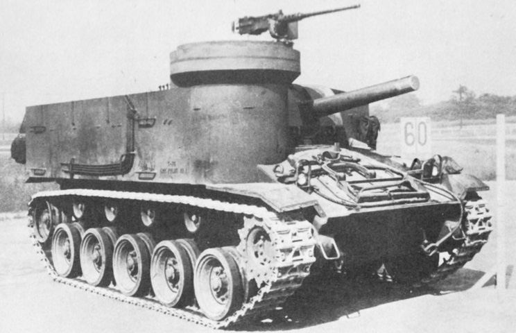
This machine is fully stowed, and the driver's hatch is open with a foul-weather hood installed. Note the travel lock for the .50cal machine gun. (Picture from ORD 9 SNL G-236 (Includes SNL G-238).)
The opposite side of the vehicle is shown here. (Picture from FM 6-76 Service of the Piece, 105mm Howitzer Motor Carriage, M37.)
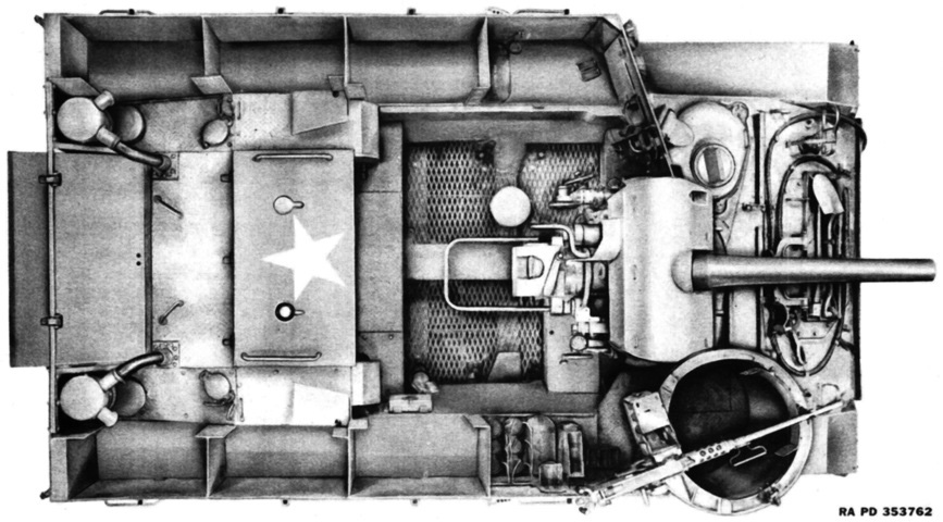
The interior layout is shown here. The engines' air cleaners can be seen in the rear corners of the hull. (Picture from ORD 9 SNL G-236 (Includes SNL G-238).)
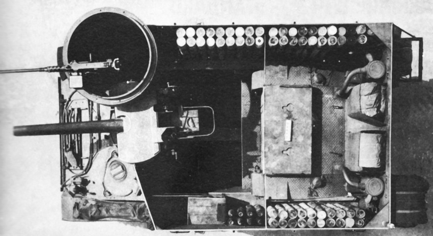
Stowage and ammunition are present in this view. (Picture from Catalogue of Standard Ordnance Items, second edition 1944, volume I: Tank and Automotive.)
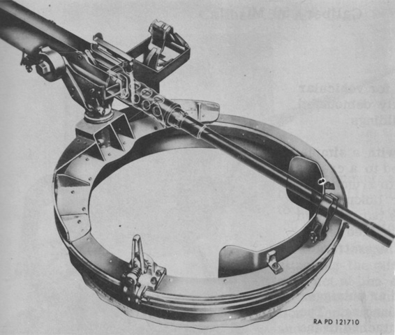
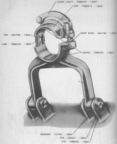
The 36"- (91cm-) diameter concentric ring mount M68 was standardized from the T107 and used roller-bearing construction. The machine gun is stowed in its barrel clip here. (Picture from Weapon Mounts for Secondary Armament.)
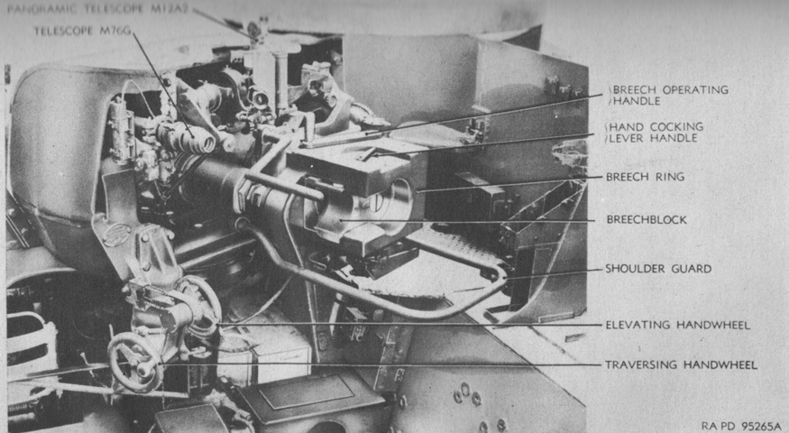
An overview of the howitzer mount M5 is shown from the rear. The electric firing switch was on the left elevation handwheel. (Picture from TM 9-324 105-mm Howitzer M4 (Mounted in Combat Vehicles).)
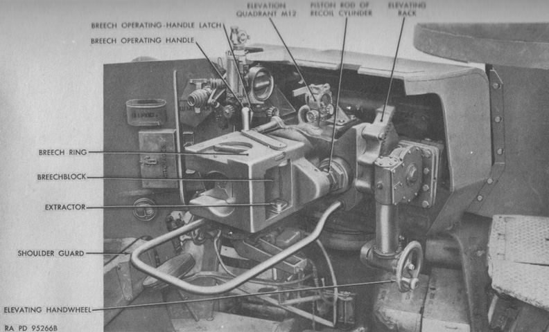
The howitzer mount is seen from the left rear. The mount weighed 3,030lb (1,370kg) and was 117.5" (298.5cm) long including the recoil guard with the howitzer installed. (Picture from TM 9-324 105-mm Howitzer M4 (Mounted in Combat Vehicles).)
A second elevation handwheel was found on the right side of the howitzer mount. (Picture from TM 9-324 105-mm Howitzer M4 (Mounted in Combat Vehicles).)
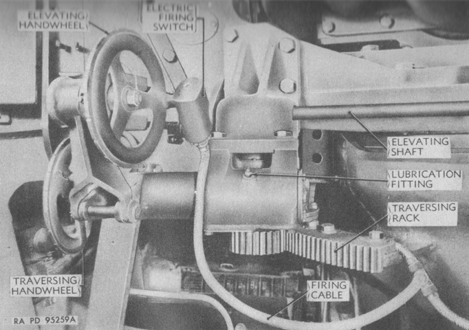
The left-side handwheels are isolated in this picture, with the electric firing switch also visible. A full rotation of the elevation handwheel provided 25.8 mils of elevation, while each turn of the traversing handwheel also yielded 25.8 mils of traverse. (Picture from TM 9-324 105-mm Howitzer M4 (Mounted in Combat Vehicles).)
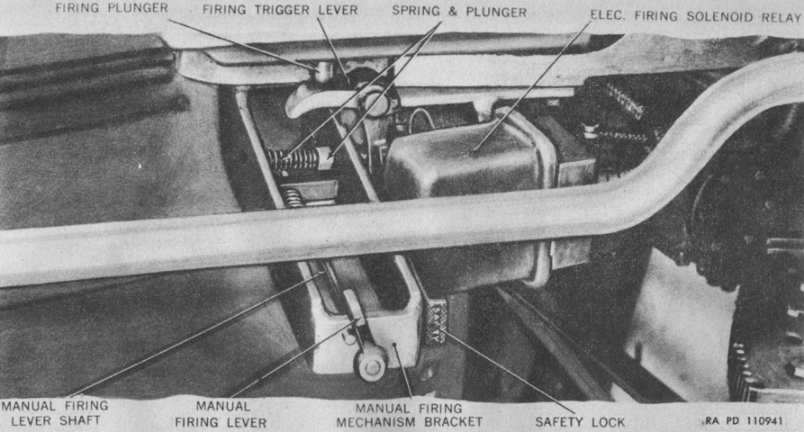
The manual firing lever was below the shoulder guard, and was depressed to fire the ordnance. (Picture from TM 9-324 105-mm Howitzer M4 (Mounted in Combat Vehicles).)
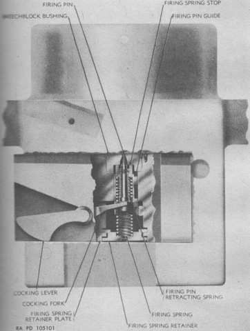
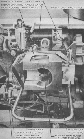
The howitzer firing mechanism is diagrammed in this ghosted image of the breech. Opening the breech or rotating the hand-cocking lever handle caused the cocking fork to retract the firing pin guide and its attached firing pin to the cocked position, where it was held by the sear. When fired, the sear was actuated, releasing the firing pin guide to fly forward so that the firing pin would strike the primer on the cartridge case. The firing pin was then pulled back into the breechblock to prevent the pin from being sheared off as the breechblock was opened. (Picture from TM 9-324 105-mm Howitzer M4 (Mounted in Combat Vehicles).)
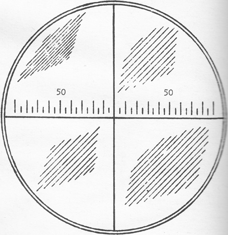
The panoramic telescope M12 was identical to the M12A2 except for the reticle pattern. As shown above, the M12 had a vertical cross line for sighting on an aiming point, and a horizontal cross line graduated in 5-mil intervals and numbered at 50 mils on each side for estimating small deflection angles. (Picture from TM 9-324 105-mm Howitzer M4 (Mounted in Combat Vehicles).)
The howitzer travel lock is detailed in this diagram. (Picture from ORD 9 SNL G-236 (Includes SNL G-238).)
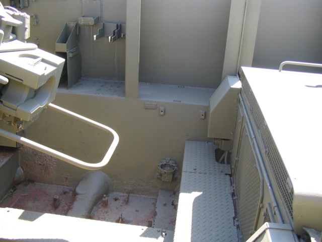
The rear of the fighting compartment is shown here. The breech of the howitzer can be seen to the left, and the radiator air inlet grilles of the engines are on the right. The panel on top of the air inlet grilles is the radiator cover. Bins for the horizontally-stowed ammunition can be seen to the rear of the fighting compartment sides, and a mount for a portable fire extinguisher can be seen to the front of the image. With the expanded metal floor missing from this vehicle, the location of some of the suspending torsion bars is visible running across the bottom of the fighting compartment.
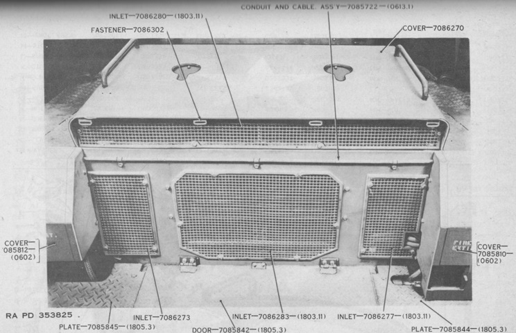
The front of the radiator air inlets are viewed in this image. (Picture from ORD 9 SNL G-236 (Includes SNL G-238).)
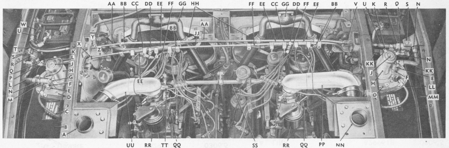
The engine compartment covers have been removed, providing access to the engines, fuel tanks, and batteries. The front of the carriage is to the top of the image. A. Elbow, left. B. Tank, ass'y (complete). C. Conduit and cable, ass'y. D. Pump, ass'y (complete). E. Bushing. F. Nipple. G. Plug. H. Neck. J. Cap, ass'y. K. Valve. L. Hose. M. Tee. N. Elbow. P. Elbow. Q. Nipple. R. Valve. S. Screw/washer. T. Conduit. U. Absorber. V. Boot. W. Conduit. X. Grommet. Y. Hose. Z. Tube. AA. Conduit. BB. Clip. CC. Clamp. DD. Tee. EE. Hose. FF. Hose. GG. Inlet. HH. Radiator. JJ. Tube. KK. Hose. LL. Conduit and cable, ass'y. MM. Tank, ass'y (complete). NN. Elbow, right. PP. Elbow, right. QQ. Carburetor. RR. Cleaner. SS. Shaft. TT. Filter, ass'y. UU. Elbow, left. (Picture from ORD 9 SNL G-236 (Includes SNL G-238).)
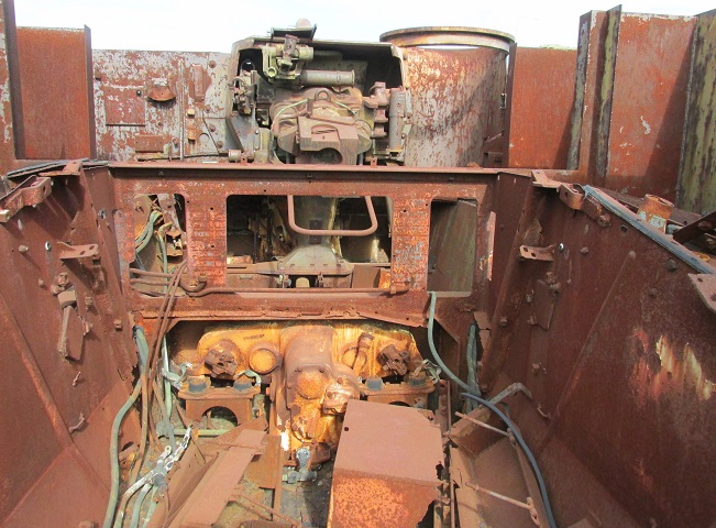
With the engines and transmissions removed, the transfer unit can be seen at the front of the engine compartment, with a coupling on each side for the separate transmissions. The transfer unit combined the power output of the two engines and provided two forward and one reverse speed ranges; the transmissions themselves did not have a reverse gear. One engine could also be decoupled at the transfer unit. The radiator air inlets are above the transfer case, but their grilles are missing. The howitzer mount and machine gun position are visible to the front.
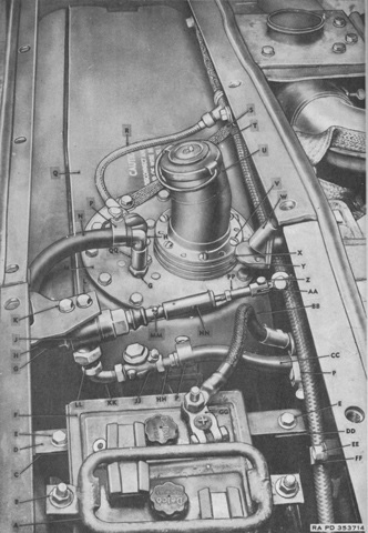
The fuel tanks and batteries flanked the engine compartment, as on the light tank M24. The rear of the carriage is towards the top of the image. (Picture from ORD 9 SNL G-236 (Includes SNL G-238).)
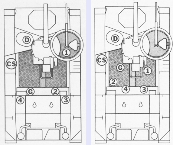
The crew's mounted posts are sketched on the left. CS was the chief of section, G was the gunner, D was the driver, and 1-4 were the cannoneers.
The crew's action posts are shown on the right. During indirect fire missions, the chief of section was to relay all fire commands from the battery executive; ensure that all commands were performed quickly and accurately; measure the minimum quadrant elevation; inform the gunner of the aiming or referring point; lay the ordnance for elevation, assisted by cannoneer number 1, when using the gunner's quadrant; measure the range or elevation; indicate when the piece was ready to fire; give the fire command; report errors or unusual incidents to the battery executive; conduct prearranged firing schedules; record basic data; note functioning of equipment at frequent intervals; check all rounds that have been prepared for firing, but remain unused, before they are placed back into their containers; assign duties under unusual conditions; and control the movement of the carriage. The gunner was to set or adjust deflection; apply deflection difference; lay the piece for direction; call, "Ready" when ready to fire; refer the piece; record the base deflection; and measure the deflection. Cannoneer number 1 was to set angle of site, range, and elevation; lay the piece for range; operate the breech; call, "Set" when ready; fire the piece; and man the machine gun when instructed. Cannoneer number 2 was to load the piece; call out the number of the round; inspect the chamber and bore after each round is fired; set out aiming posts when ordered; and dispose of used cartridge cases. Cannoneer number 3 was to place packaged ammunition on the carriage's radiator cover; remove the rounds from their containers; clean and inspect the projectiles; set the fuze setter; cut or set the fuzes; and reset fuzes and replace unfired rounds into their containers. Cannoneer number 4 was to pass packaged rounds to cannoneer number 3; accept projectiles and cartridge cases from cannoneer number 3; clean and inspect the cartridge cases; prepare the charges; assemble the rounds; place the prepared rounds on the carriage's radiator cover; and replace into the cartridge cases the propellant increments of all rounds prepared for firing but remaining unused. The driver was to remain at his post and move the carriage under the direction of the chief of section or gunner. (Picture from FM 6-76 Service of the Piece, 105mm Howitzer Motor Carriage, M37.)
