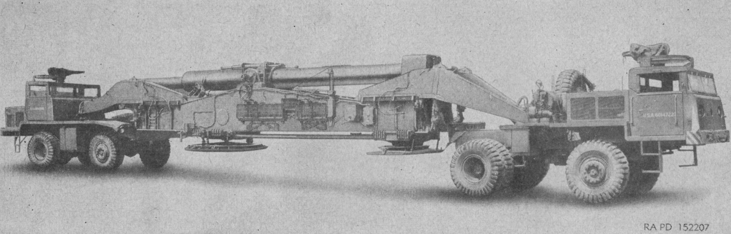
280mm Motorized Heavy Gun M65.
The M65 was certainly an imposing sight limbered and ready for travel. The gun carriage M30 is slung between the two gun lifting trucks--the leading M249 at the right of the image and the trailing M250 at the left--and the 280mm gun M66 is retracted. The trucks each have a ring mount for a .50cal machine gun in this image, and an interphone system allowed the two trucks to communicate with each other. (Picture from TM 9-338-1 C2 280-mm Gun T131 and 280-mm Gun Carriage T72.)
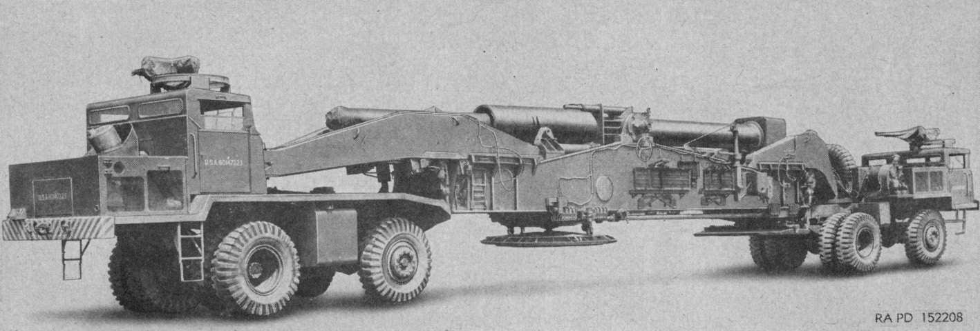
The system is viewed from the right rear. Differences in the two gun lifting trucks can be seen, with the M249 having its engine above the front wheels and cab forward of the engine, while the M50 had its cab above the rear wheels and engine hanging off the rear of the truck. Both trucks had single steering wheels and dual rear wheels. (Picture from TM 9-338-1 C2 280-mm Gun T131 and 280-mm Gun Carriage T72.)
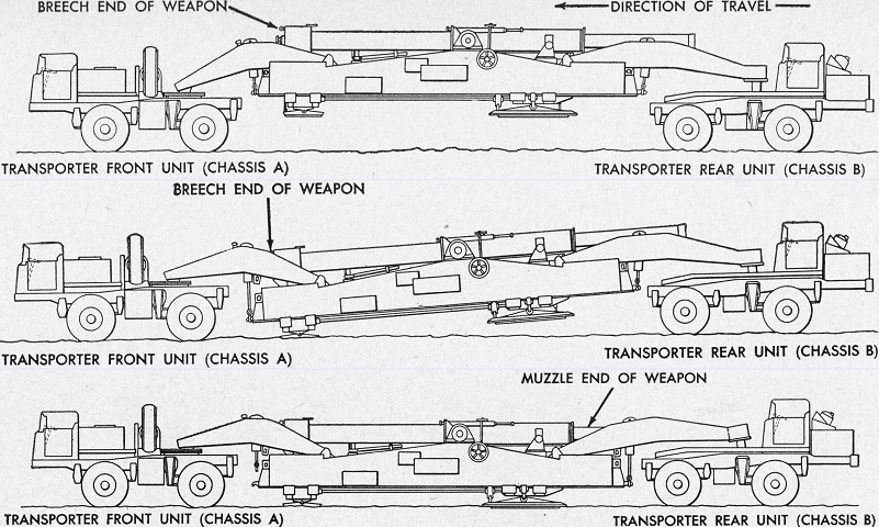
The carriage was slung between the transporters with the breech end of the gun forward. When the gun was emplaced, the breech end was lowered first, followed by the muzzle end. (Picture from TM 9-338-1 C2 280-mm Gun T131 and 280-mm Gun Carriage T72.)
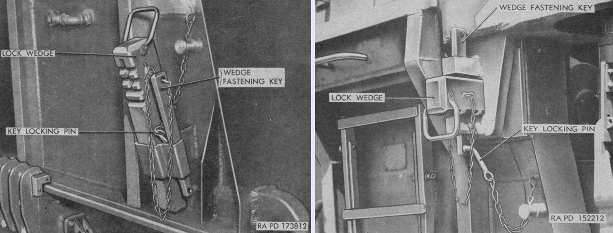
Each corner of the carriage was secured to the lifting forks of the transporters by lock wedges and fastening keys. As seen on the left, these were stowed in pockets when not needed; the wedge is installed on the right. The wedge was a tapered square steel forging with notches cut into its underside to facilitate withdrawal with a pinch bar. The fastening key was inserted into the wedge vertically, and the end of the key accepted a locking pin that was secured by a keyslot detent. (Picture from TM 9-338-1 C2 280-mm Gun T131 and 280-mm Gun Carriage T72.)
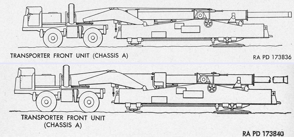
After the carriage was lowered, the front transporter remained attached. As shown in the top image, the winch on this truck was used to pull the gun tube to its in-battery position by reeving the retracting cable through the sheave on the cradle and attaching the shackle to the retracting eye plate on the front of the breech ring. Illustrated on the bottom, the gun tube was retracted by attaching the retracting cable to the rear retracting eye on the breech ring and winching it into position. (Picture from TM 9-338-1 C2 280-mm Gun T131 and 280-mm Gun Carriage T72.)
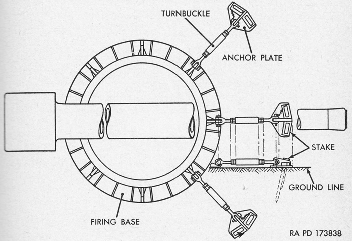
Three stabilizing anchors were attached to hooks on the firing base to help secure the carriage to the ground. The central anchor was to lie below the gun tube, and the other two 45° to either side of the central anchor. Details of this arrangement may have been modified on later carriages, but the principle remained. (Picture from TM 9-338-1 C2 280-mm Gun T131 and 280-mm Gun Carriage T72.)
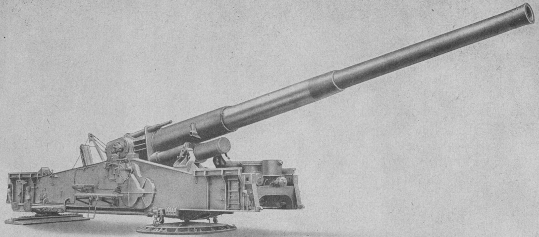
The 280mm gun carriage carriage M30 has been emplaced, and the M66 gun has been deployed. The carriage weighed 94,000lb (42,600kg) and was 38'5" (11.7m) long in this configuration. (Picture from TM 9-338-1 C2 280-mm Gun T131 and 280-mm Gun Carriage T72.)
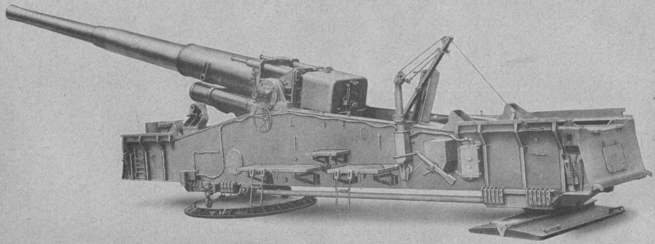
Platforms for the gun crew were installed on each side of the carriage, and a davit for lifting the ammunition into the carriage was found on the left exterior wall. (Picture from TM 9-338-1 C2 280-mm Gun T131 and 280-mm Gun Carriage T72.)
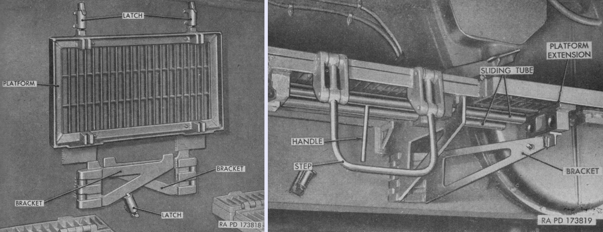
Folding platforms were secured vertically against the carriage for travel, and were lowered to the firing position when the carriage was emplaced. (Picture from TM 9-338-1 C2 280-mm Gun T131 and 280-mm Gun Carriage T72.)
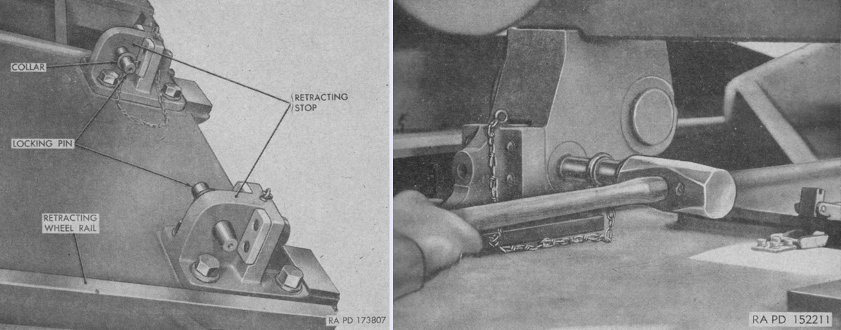
The gun tube was held in the retracted position by locking pins in the retracting stops. The stops featured self-releasing detents that prevented the pins from jolting out of the stops. When not in use, the pins were stowed in the stops as in the left image; they are being inserted on the right. (Picture from TM 9-338-1 C2 280-mm Gun T131 and 280-mm Gun Carriage T72.)
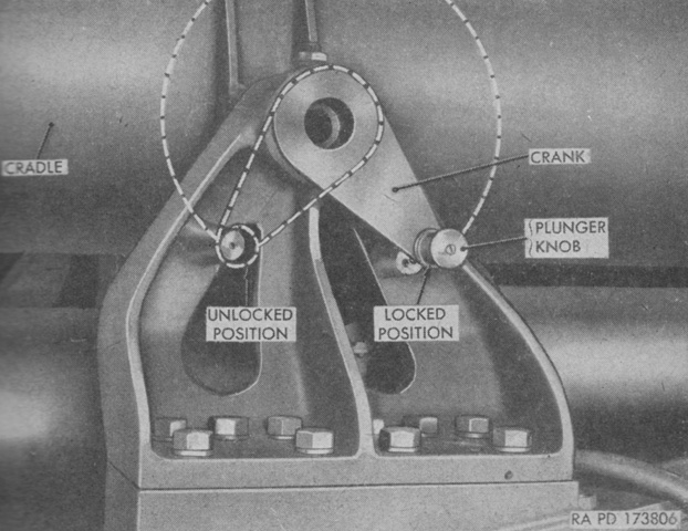
During travel or when elevation prevention was desired, the gun cradle was secured at 0° elevation with tapered locking pins that inserted into sockets in the cradle via a spiral groove. These were engaged or disengaged by a crank handle on each side of the top carriage forward of the trunnions. The spring-loaded plunger knob locked the crank into a detent to prevent unintended movement. (Picture from TM 9-338-1 C2 280-mm Gun T131 and 280-mm Gun Carriage T72.)
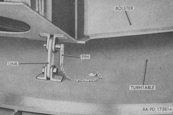
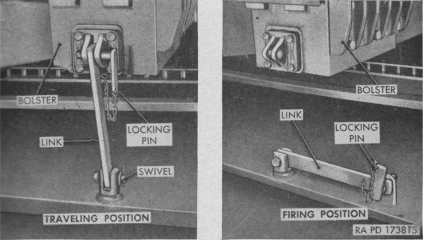
The firing base had a travel lock that secured it to the firing base bolster. The hinged link was erected and a pin was inserted through holes in the link and lugs on the firing base bolster. (Picture from TM 9-338-1 C2 280-mm Gun T131 and 280-mm Gun Carriage T72.)
The float as well had travel locks that secured it to the float bolster. They functioned in a similar manner to those for the firing base. (Picture from TM 9-338-1 C2 280-mm Gun T131 and 280-mm Gun Carriage T72.)
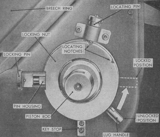
A primary recoil lock was located on each lower corner of the breech ring, and either secured the primary recoil piston rods to the breech ring for firing or disconnected the rods for gun tube retraction to the traveling position. These were circular interrupted thread locking nuts that rotated 45° around the piston rods to engage or disengage locking threads. A spring-loaded locking pin seated into the piston rod to secure the locking nut in the closed position, but this pin was held out of the rod when turned 90° and instead seated in a shallow notch in the pin housing. The self-releasing locating pin engaged notches on the nut when opened or closed. The right and left locks were made with right and left threads, respectively, so that the operation of both locks was the same. (Picture from TM 9-338-1 C2 280-mm Gun T131 and 280-mm Gun Carriage T72.)
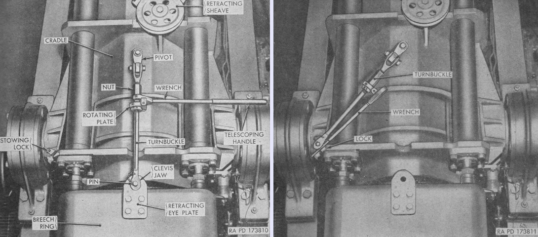
In order to relieve tension on the recoil rods when trying to open or close the primary recoil locks, it was necessary to draw the breech ring up to the cradle. This was accomplished by the breech ring turnbuckle take-up, which was attached to the cradle with a pivot that allowed it to be stowed when not in use. The take-up was attached to the retracting eye plate on the breech ring, and the turnbuckle nut was turned with a telescoping wrench. The take-up is shown deployed on the left and stowed on the right. (Picture from TM 9-338-1 C2 280-mm Gun T131 and 280-mm Gun Carriage T72.)
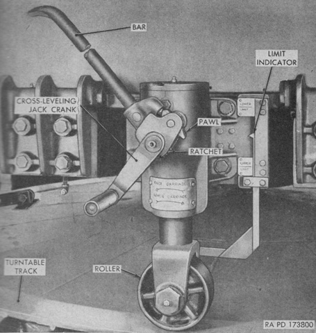
The gun trunnions were brought into a horizontal position by a cross-leveling jack crank on each side of the firing base bolster. Each crank would raise or lower the roller against the turntable track and thereby raise or lower one side of the carriage. The handle on the crank was held in position by a sprung detent, but could be pulled out and aligned with the crank arm so that it could instead be used as a lever. In addition, a pawl and spring loaded ratchet was attached to the crank shaft for increased leverage when used with a bar. The cranks on each side were always to be used together so that both rollers remained in contact with the turntable to prevent binding of the jack mechanisms. (Picture from TM 9-338-1 C2 280-mm Gun T131 and 280-mm Gun Carriage T72.)
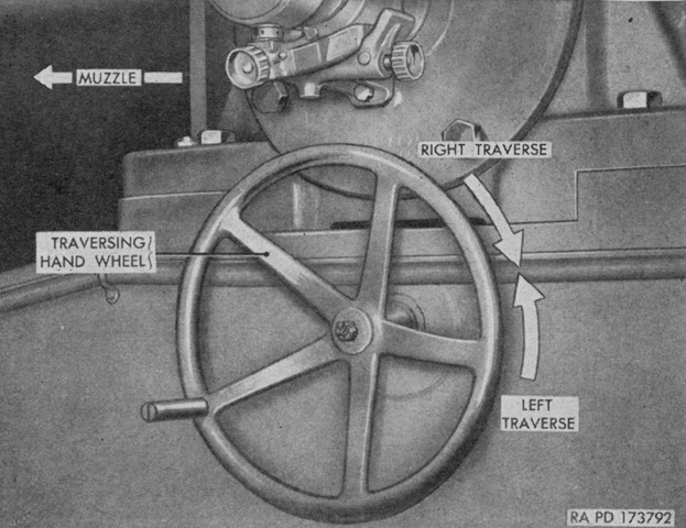
The traversing handwheel was found on the left side of the carriage under the gun trunnion. The handwheel provided a traversing arc of 7½° to the left or right. (Picture from TM 9-338-1 C2 280-mm Gun T131 and 280-mm Gun Carriage T72.)
The traversing arc available with the traversing handwheel is illustrated here. If the gun needed to be traversed more than the handwheel allowed, the float could be raised to allow the carriage rear to be pushed into the correct orientation. (Picture from TM 9-338-1 C2 280-mm Gun T131 and 280-mm Gun Carriage T72.)
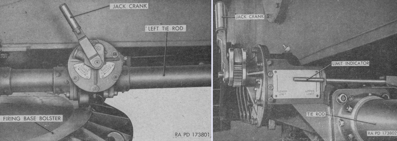
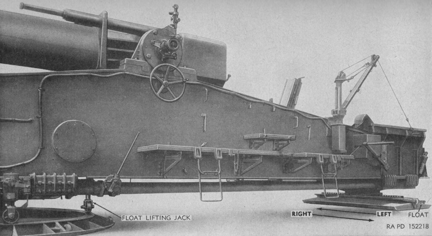
The carriage float was raised by the float lifting jack crank located on the left tie rod just behind the firing base bolster and operated in a similar manner to the cross-leveling jack cranks. To traverse the gun beyond the fine traverse limits, the tube was first placed at 0° elevation and traverse. The float was then raised with its lifting jack, and the rear of the carriage was pushed in the desired direction. The float was lowered to the ground when the proper direction was reached, and the float jack roller was raised to clear the turntable. Finally, the anchors were reset in the proper orientation and cross-leveling was rechecked. (Picture from TM 9-338-1 C2 280-mm Gun T131 and 280-mm Gun Carriage T72.)
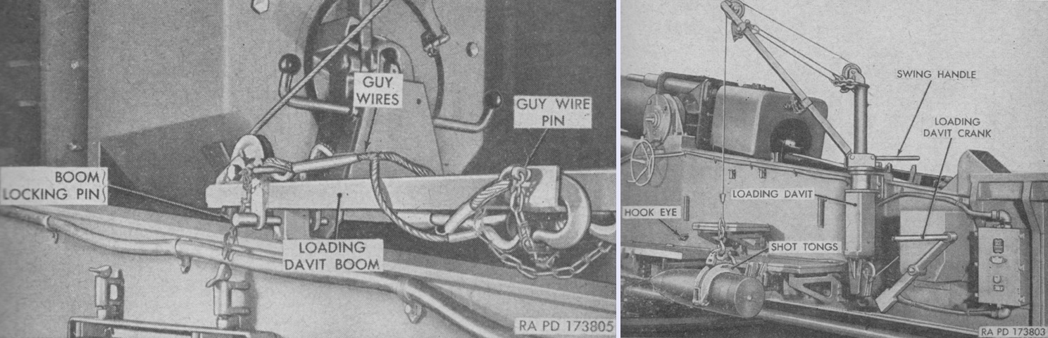
The loading davit is seen on the left stowed for travel, and deployed on the right with a shell in the tongs. The davit was used to raised the projectile and powder charge into the loading trough. The lifting davit was definitely a necessity, as the propelling charge T44 weighed ~157lb (~71.2kg), the high-explosive shell T122 weighed ~605lb (~274kg), the W9 nuclear shell weighed over 800lb (360kg), and the W19 nuclear shell weighed 600lb (270kg). (Picture from TM 9-338-1 C2 280-mm Gun T131 and 280-mm Gun Carriage T72.)
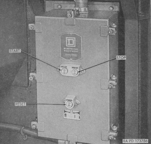
Located on the left rear side of the top carriage, the power system motor control switch started and stopped the motor that operated the power system hydraulic pump. The reset button operated a thermal type circuit breaker to reestablish the circuit after it was broken by excessive current. (Picture from TM 9-338-1 C2 280-mm Gun T131 and 280-mm Gun Carriage T72.)
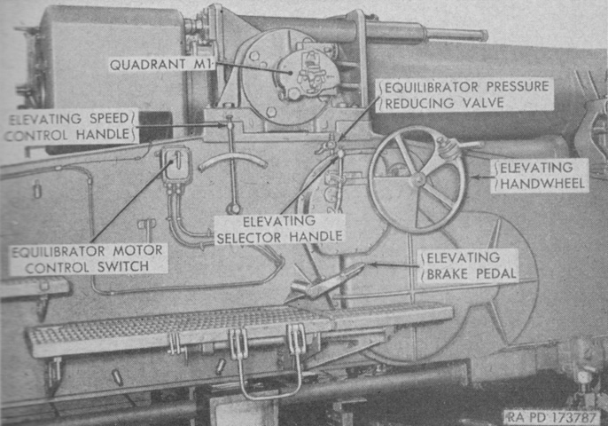
Elevation controls were on the right side of the carriage. The elevating selector handle was used to select manual or power elevation. The elevating speed control handle operated the power elevation system to elevate the gun between 5° and 50°. The elevating handwheel was used for manual elevation, and the full 0° to 55° of elevation was available with the handwheel. The elevating brake pedal applied or released the elevating brake, which was always engaged unless the operator stepped on the pedal. The equilibrator motor control switch started or stopped the pump that increased pressure in the equilibrator system, while the equilibrator pressure reducing valve allowed pressure in the equilibrator system to be reduced. These equilibrator controls were used to ease operation of the elevating handwheel when elevating or depressing the gun, respectively. (Picture from TM 9-338-1 C2 280-mm Gun T131 and 280-mm Gun Carriage T72.)
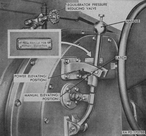
The elevating selector handle is highlighted in this image. The handle could be moved between the two notches by depressing the spring-loaded plunger and moving the lever to the desired location. When in the power elevating position, the handwheel clutch was disengaged, and a valve admitting hydraulic pressure into the elevating motor was opened. The opposite occurred when in the manual elevating position. (Picture from TM 9-338-1 C2 280-mm Gun T131 and 280-mm Gun Carriage T72.)
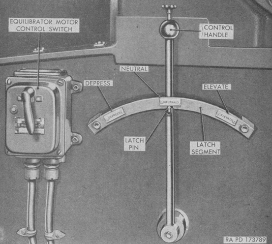
The elevating speed control handle also had a spring-loaded plunger that allowed the handle to be held in the neutral position. To elevate or depress the gun, the plunger was depressed and the handle moved in the appropriate direction. The power system hydraulic pump supplied pressure to both the elevating and rammer hydraulic motors, so in order to make the control of the pump more convenient the elevating speed control handle and the rammer control handle were interconnected. The loading trough position actuated selector valves that directed pressure to either the elevating or rammer motors, meaning that the gun could not be hydraulically elevated with the elevating speed control handle unless the trough was in the firing position. The latch pin on the elevating speed control handle could be locked out of the notch by rotating the plunger clockwise after it was pushed, which would allow the rammer control handle to be used. (Picture from TM 9-338-1 C2 280-mm Gun T131 and 280-mm Gun Carriage T72.)
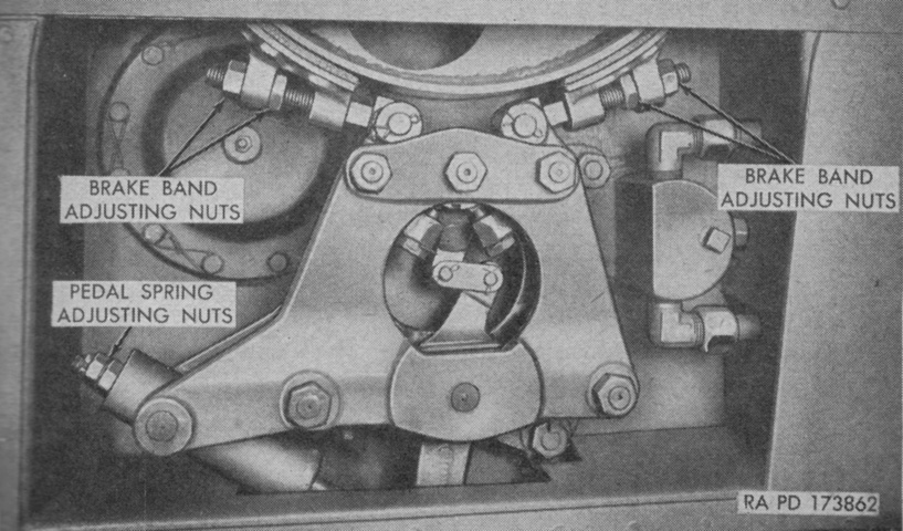
The elevating brake was a single-shoe type equipped with a spring actuated lever mechanism that ensured the brake was applied unless the elevating brake pedal was depressed. The brake wheel gripped by the brake shoes was attached to a shaft and gear meshed with the elevating gear train. The brake could hold the gun tube at any elevation or angle, and needed to be released before any changes in elevation could occur. (Picture from TM 9-338-1 C2 280-mm Gun T131 and 280-mm Gun Carriage T72.)
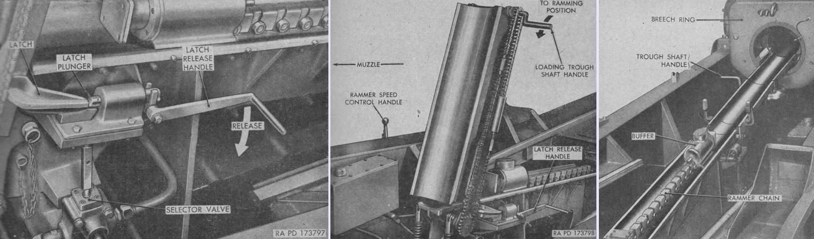
Latches holding the loading trough vertically in the firing position were released by moving their release handle down, as shown on the left. The trough was then moved down to the ramming position with the loading trough shaft handle and extended forward into the breech. The chain worked to swing the forward section of the trough upwards into the breech and aligned the trough sections at an upward 11° angle, as seen on the right. When the trough was folded into the firing position, two selector valves diverted hydraulic pressure from the rammer hydraulic motor to the elevating hydraulic motor. (Picture from TM 9-338-1 C2 280-mm Gun T131 and 280-mm Gun Carriage T72.)
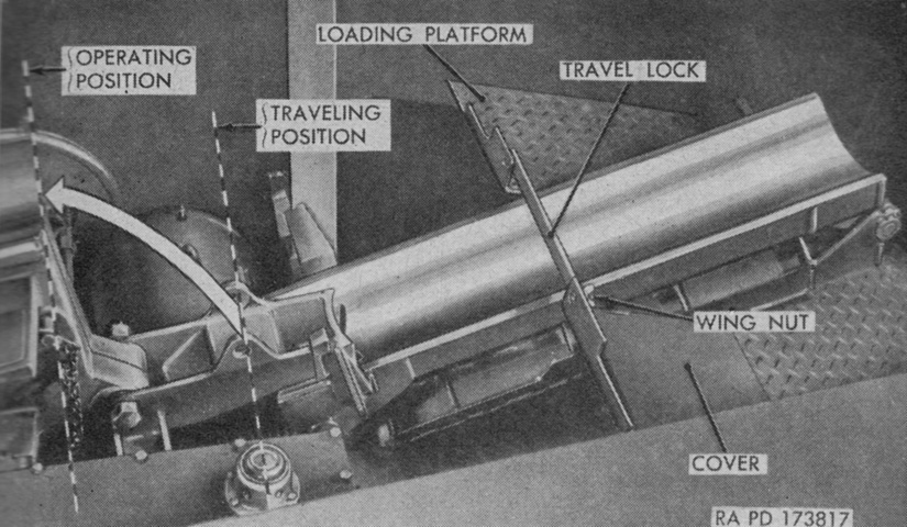
The loading trough was secured for travel by a hinged lock secured with a wing nut. A locking pin secured the trough in the operating position; once this was removed, the trough could be lowered forward into the traveling position under its travel lock. (Picture from TM 9-338-1 C2 280-mm Gun T131 and 280-mm Gun Carriage T72.)
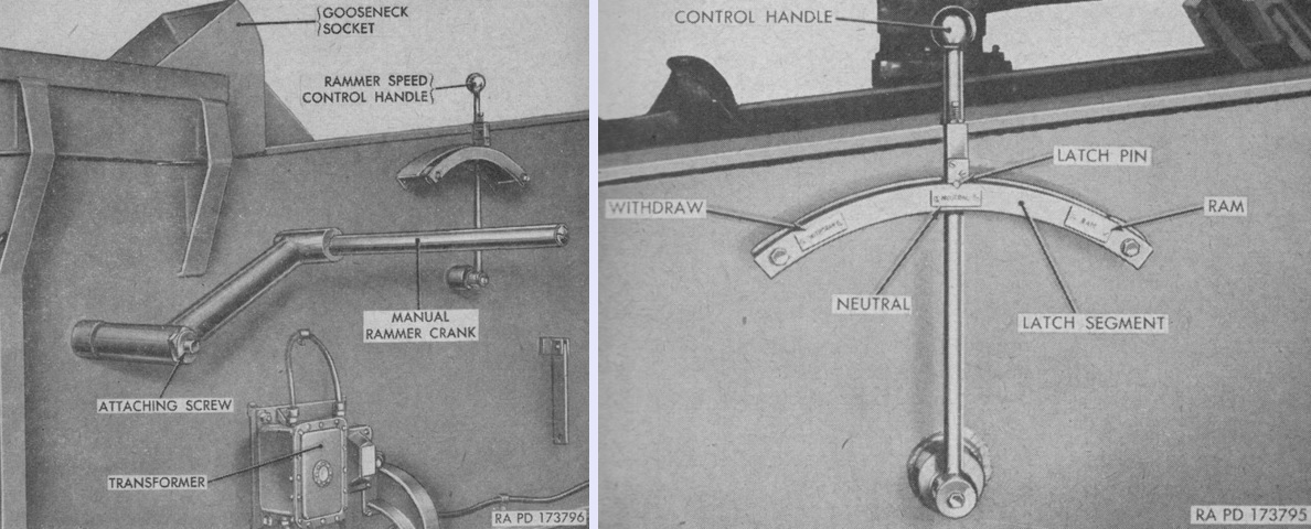
Rammer controls are shown above. The manual rammer crank was normally stowed, but when needed could be attached to a shaft connected to the rammer mechanism on the carriage's right rear side. It could be used to withdraw the buffer head or move the ramming chain for reasons other than projectile ramming, although improvised methods to depress the selector valve plungers might be needed to move the buffer head with the manual crank.
The rammer speed control handle isolated on the right was used to operate the power ramming system. The handle would automatically return to the neutral position, and a self-releasing latch pin engaged a notch in the latch segment to hold the handle there. Since the ramming and elevating speed control handles were interconnected, the elevating speed control handle latch pin needed to be locked out of its segment notch to permit movement of the ramming speed control handle. (Picture from TM 9-338-1 C2 280-mm Gun T131 and 280-mm Gun Carriage T72.)
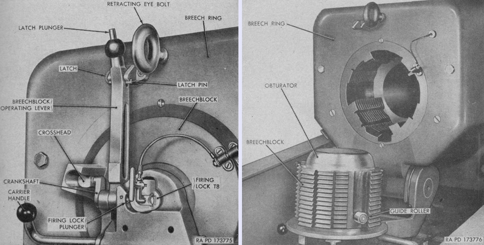
The cylindrical, interrupted step-thread gun breech is seen closed on the left and open on the right. It swung vertically on a hinged carrier, and gas erosion was prevented by a DeBange type obturator. To open the breech, the latch plunger on the breechblock operating lever was depressed and the lever was then pulled back. Once opened, the carrier handles were pushed downward until the breech was secured into the open position. A counterbalance in the lower part of the breech ring assisted with the weight of the breechblock. The firing lock plunger at the base of the breechblock operating lever prevented the firing lock from being opened unless the breechblock was fully closed. The guide roller on the breechblock ensured the locking threads were aligned when closing the breech. The retracting eye bolt used to withdraw the tube into the traveling position is also visible on the upper face of the breech ring. (Picture from TM 9-338-1 C2 280-mm Gun T131 and 280-mm Gun Carriage T72.)
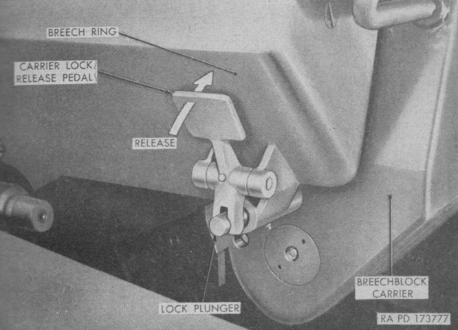
When opened, the breechblock carrier was secured by a spring-loaded plunger. The carrier lock release pedal withdrew the plunger when the breechblock was to be closed, then the breechblock could be raised into the breech by lifting the carrier handles. The breech was locked into the closed position by securing the breechblock operating lever in its latch. (Picture from TM 9-338-1 C2 280-mm Gun T131 and 280-mm Gun Carriage T72.)
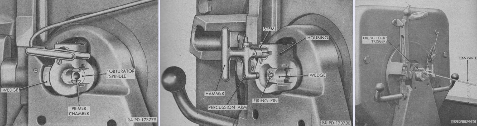
The firing lock T8 was shared with the 155mm SPH M44, and was a detachable, manually-operated device that opened and closed the primer chamber, seated and extracted the primer cartridge, provided contact for electrical firing, and incorporated a hammer for percussion firing. The T8 is seen in the open position on the left and cocked in the center image. When electrical firing was to be used, the firing lock was pulled out to its first stop (~⅛" [~.318cm]) and turned counterclockwise until the electrical primer could be inserted. It was then turned clockwise until the wedge was fully closed and the handle was vertical. For percussion firing, the firing lock was opened and a percussion primer inserted. Then the handle was turned clockwise and pulled rearward. When the handle was turned ~45°, it was able to be pulled out ~1" (2.5cm). The handle was further turned until it was locked in the vertical, or cocked, position. The firing lock trigger seen on the right was used to fire the gun via percussion. When a lanyard was hooked to the trigger eye with a pull-off clip and then pulled from an off-carriage position, the trigger tripped a sear and fired the gun. (Picture from TM 9-338-1 C2 280-mm Gun T131 and 280-mm Gun Carriage T72.)
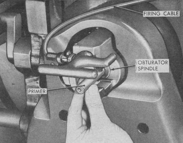
The firing lock has been opened and the primer is being inserted in this picture. (Picture from TM 9-338-1 C2 280-mm Gun T131 and 280-mm Gun Carriage T72.)
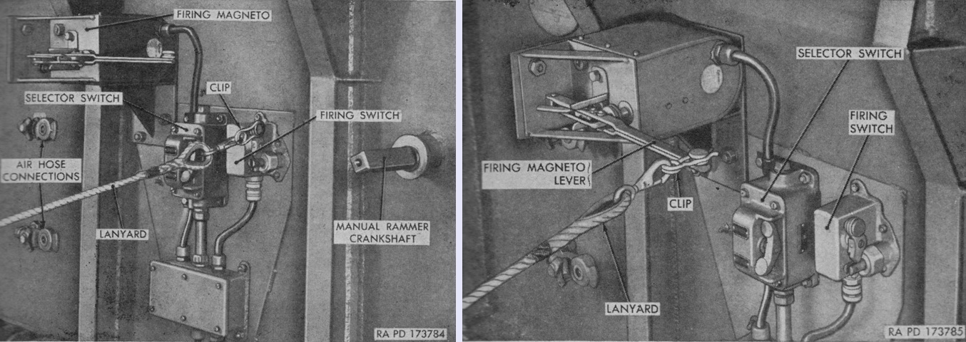
The selector switch provided an alternate firing circuit if the off-carriage power source failed or malfunctioned. It completed the firing circuit when using the on-carriage transformer, which was used to reduce the voltage supplied from an off-carriage generator to that required by the firing circuit; alternatively, it completed the firing magneto circuit in the case of power failure. The upper button was used for the transformer circuit, and the lower for the magneto circuit. The firing switch was used to fire the gun electrically via the transformer firing circuit. As seen on the left, the lanyard was attached to the switch with a pull-off clip and pulled from an off-carriage position to fire the gun. Use of the firing magneto is shown on the right. The firing magneto lever was an automatic returning type, and the lanyard's pull-off clip was attached to its end to fire from an off-carriage position. Note that in this illustration, the selector switch shows that the transformer circuit has been chosen, not the magneto circuit. (Picture from TM 9-338-1 C2 280-mm Gun T131 and 280-mm Gun Carriage T72.)
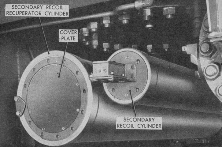
The primary recoil mechanism M32 had a 49 gallon (485L) capacity with a 9 pint (4.259L) reserve in the recuperator. Maximum allowable recoil for the primary system was 42" (110cm) at 55° elevation and 32" (81cm) at 10° elevation. The secondary recoil mechanism T81 or M33, the front of which is seen here, was secured to the bottom carriage and operated only in a horizontal plane. It possessed a 20½ gallon (77.6L) capacity with a 2½ pint (1.183L) reserve in the recuperator. Maximum allowable recoil for this system was 40" (100cm) at 55° and 96" (240cm) at 10°. (Picture from TM 9-338-1 C2 280-mm Gun T131 and 280-mm Gun Carriage T72.)
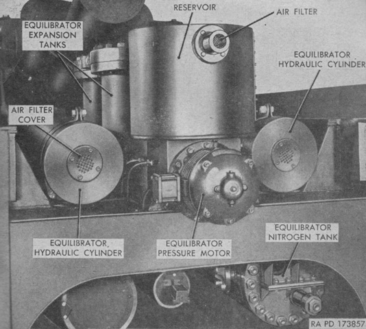
The hydropneumatic equilibrator was composed of a nitrogen cylinder, two expansion tanks, two hydraulic cylinders, and an oil reservoir and pump. Links between the elevating rack and a crosshead attached to the hydraulic pistons transferred the unbalanced weight of the gun to the hydraulic cylinders. This pressure was transferred to the nitrogen cylinder through the expansion tanks where the oil and gas were separated by floats. These floats balanced the plane of pressure between the resilience of the gas and the unbalanced weight of the gun. Pressure in the equilibrator could be increased or decreased if needed by the oil reservoir and pump or by a bleeder valve. The equilibrator had a 57 gallon (215L) capacity and an initial gas pressure of 885psi (62.2kg/cm²). (Picture from TM 9-338-1 C2 280-mm Gun T131 and 280-mm Gun Carriage T72.)
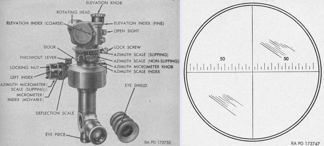
The panoramic telescope M12A7C was a 4x instrument with a 10° field of view and was used to lay the gun in azimuth. Its reticle pattern is drawn on the right, and consisted of crosshairs with a horizontal deflection scale graduated in 5-mil intervals and numbered in 50-mil intervals to either side of the center line. In addition, an open sight comprised of a peep hole and front bead was attached to the right side of the telescope for quickly locating the aiming point. (Picture from TM 9-338-1 C2 280-mm Gun T131 and 280-mm Gun Carriage T72.)
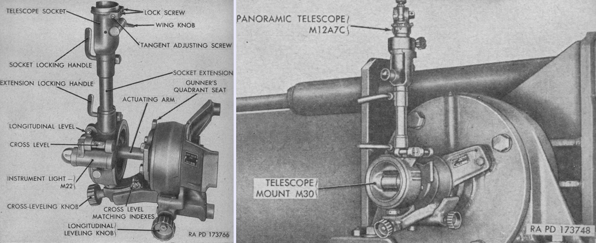
The telescope mount M30 attached to the left gun trunnion and was an azimuth compensating type that counteracted azimuth error which occurred when the gun tube was elevated with the trunnions canted. The mount is isolated in the left image and installed with the telescope on the right. The longitudinal leveling knob rotated the telescope socket in a plane parallel to the gun tube, while the cross-leveling knob rotated the telescope perpendicularly to the gun tube. The gunner's quadrant seat rotated with the trunnions and was used with the gunner's quadrant M1 on the opposite trunnion to determine if the actuating arm pivot was parallel to the gun tube. The telescope socket could fit into the extension arm as shown or directly into the mount. The eyepiece of the telescope was offset from the gun tube axis by 45° when installed in the mount for convenience of viewing. (Picture from TM 9-338-1 C2 280-mm Gun T131 and 280-mm Gun Carriage T72.)
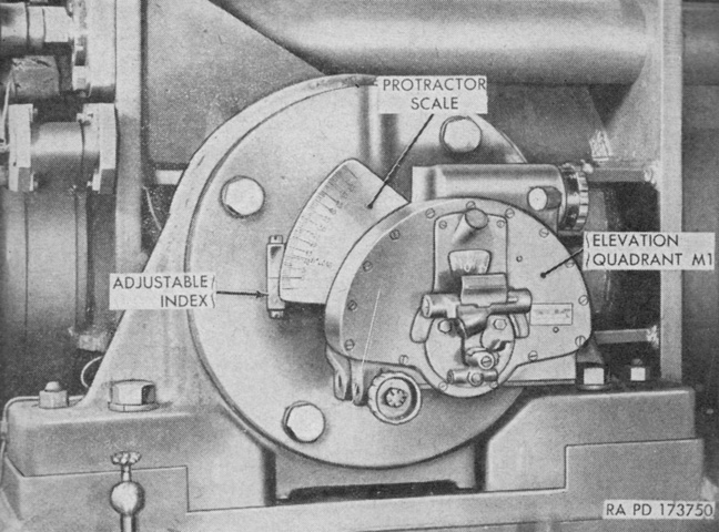
The elevation quadrant M1 was found on the opposite trunnion, mounted on the quadrant adapter M10. (Picture from TM 9-338-1 C2 280-mm Gun T131 and 280-mm Gun Carriage T72.)
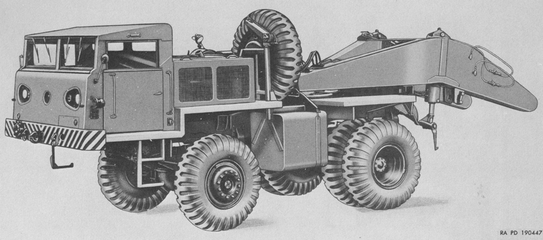
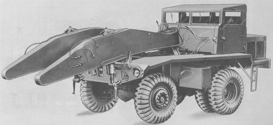
The heavy 4x4 front gun-lifting truck M249, seen from the left front, was constructed with the cab in front of the engine at the extreme front of the vehicle. The hydraulic lifting forks pointed to the rear, and an hydraulic winch and a spare wheel were present. (Picture from ORD 9 SNL G-268 List of All Service Parts of Truck, Gun Lifting, Heavy, 4 x 4, Front, M249; Truck, Gun Lifting, Heavy, 4 x 4, Rear, M250.)
The installation of the M249's winch adjacent to the spare wheel is visible from this angle. (Picture from ORD 9 SNL G-268 List of All Service Parts of Truck, Gun Lifting, Heavy, 4 x 4, Front, M249; Truck, Gun Lifting, Heavy, 4 x 4, Rear, M250.)
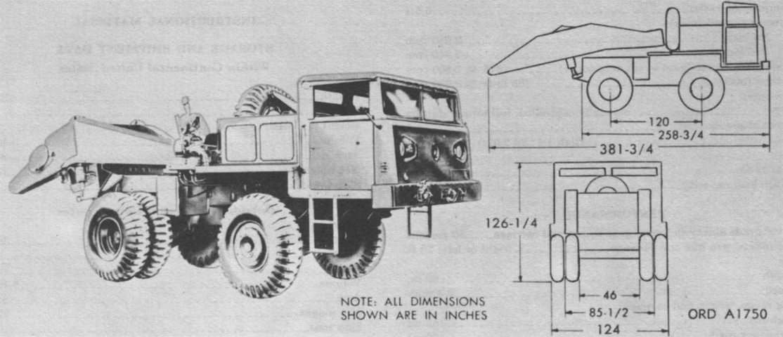
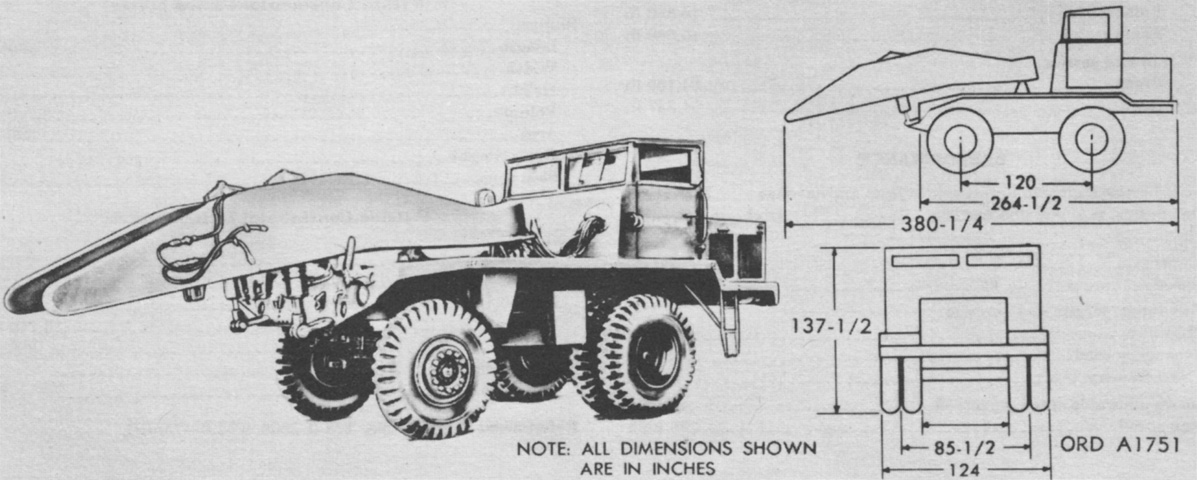
The M249's dimensions are labeled in this image. The M249 weighed 37,950lb (17,210kg), which increased to 91,625lb (41,561kg) when the portion of the gun weight carried was included. (Picture from TM 9-500 C3 Data Sheets for Ordnance Type Materiel.)
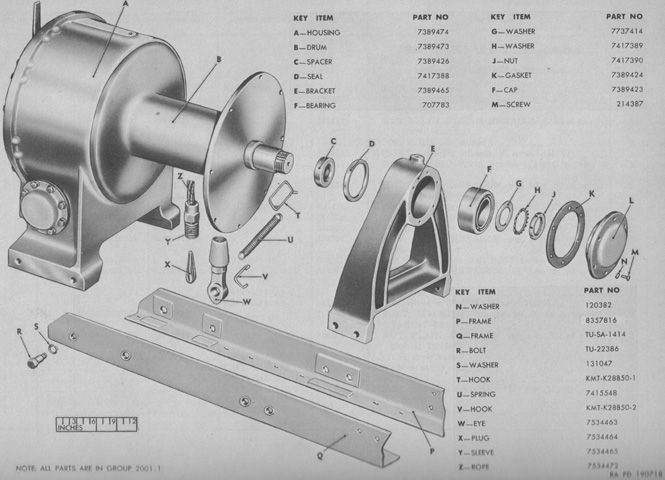
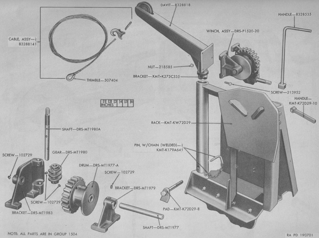
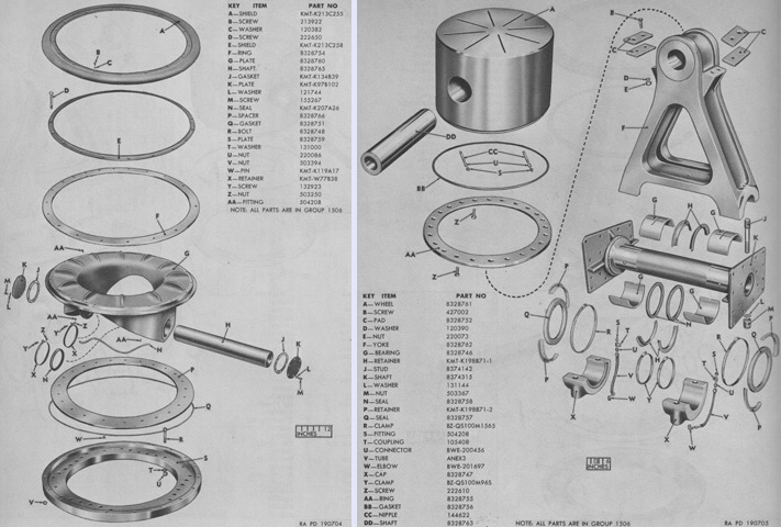
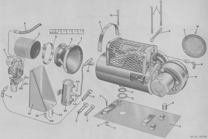
An exploded diagram of the M249's winch is provided here. (Picture from ORD 9 SNL G-268 List of All Service Parts of Truck, Gun Lifting, Heavy, 4 x 4, Front, M249; Truck, Gun Lifting, Heavy, 4 x 4, Rear, M250.)
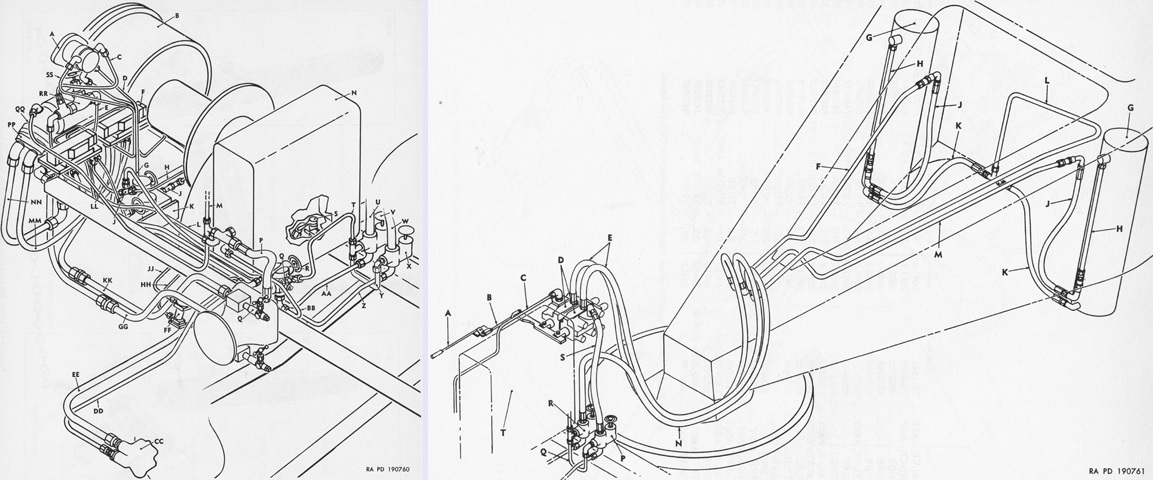
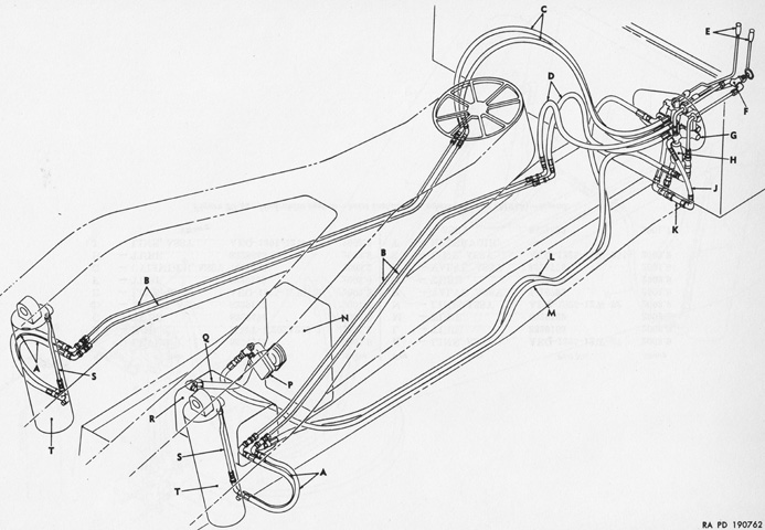
Schematic drawings of the M249's winch installation and hoist installation hydraulic systems are sketched. (Picture from ORD 9 SNL G-268 List of All Service Parts of Truck, Gun Lifting, Heavy, 4 x 4, Front, M249; Truck, Gun Lifting, Heavy, 4 x 4, Rear, M250.)
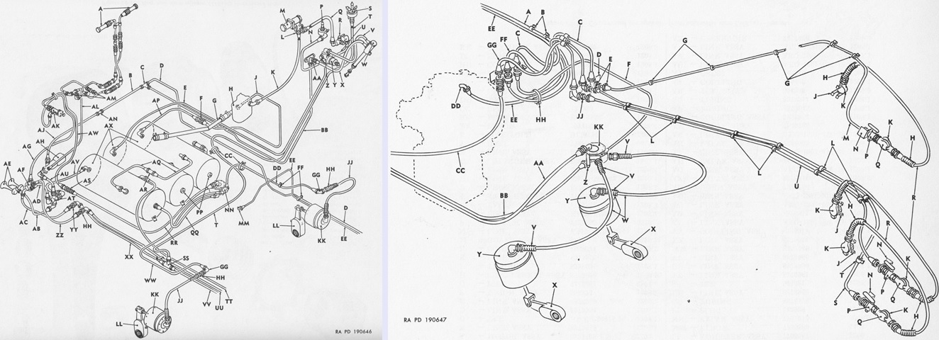
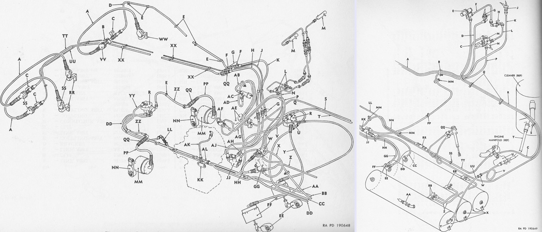
The front and rear of the compressed air system for the M249 are drawn on the left and right, respectively. (Picture from ORD 9 SNL G-268 List of All Service Parts of Truck, Gun Lifting, Heavy, 4 x 4, Front, M249; Truck, Gun Lifting, Heavy, 4 x 4, Rear, M250.)
Parts of the spare wheel carrier are illustrated here. The wheel was raised and lowered into position by a manual ratcheting winch. (Picture from ORD 9 SNL G-268 List of All Service Parts of Truck, Gun Lifting, Heavy, 4 x 4, Front, M249; Truck, Gun Lifting, Heavy, 4 x 4, Rear, M250.)
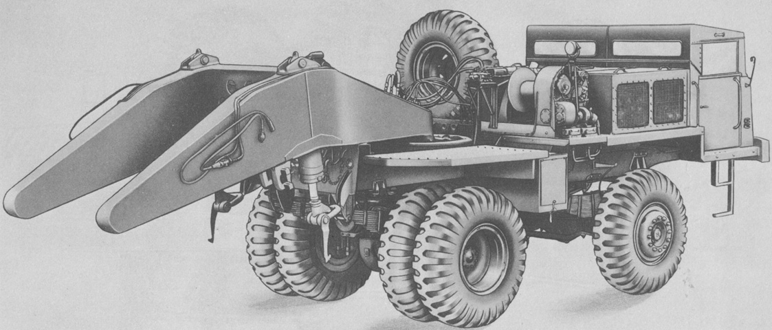
Though perhaps appearing the opposite, the heavy 4x4 rear gun-lifting truck M250 is pictured here from the front left. The hydraulic lifting forks were necessarily at the front of the vehicle, with the cab just behind and the engine at the extreme rear. Headlights are visible under the hydraulic forks, and the single-wheel axle was used for steering. The M250 was not equipped with a winch. (Picture from ORD 9 SNL G-268 List of All Service Parts of Truck, Gun Lifting, Heavy, 4 x 4, Front, M249; Truck, Gun Lifting, Heavy, 4 x 4, Rear, M250.)

The engine was installed at the rear of the M250, and the exhaust can be seen here exiting the top of the engine compartment. Taillights are visible in the apertures in the bumper to each side of the towing pintle. (Picture from ORD 9 SNL G-268 List of All Service Parts of Truck, Gun Lifting, Heavy, 4 x 4, Front, M249; Truck, Gun Lifting, Heavy, 4 x 4, Rear, M250.)
The physical dimensions of the M250 are given in these sketches. The M250 weighed 35,910lb (16,290kg), which increased to 81,240lb (36,850kg) when the portion of the gun weight carried was included. (Picture from TM 9-500 C3 Data Sheets for Ordnance Type Materiel.)
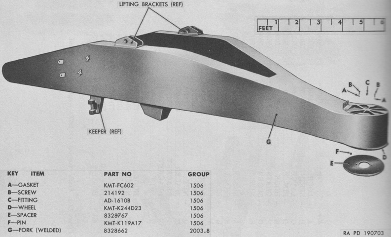
The M250's front-facing forklift boom and fifth wheel are isolated in this image. (Picture from ORD 9 SNL G-268 List of All Service Parts of Truck, Gun Lifting, Heavy, 4 x 4, Front, M249; Truck, Gun Lifting, Heavy, 4 x 4, Rear, M250.)
The hoist installation hydraulic system of the M250 is drawn here. (Picture from ORD 9 SNL G-268 List of All Service Parts of Truck, Gun Lifting, Heavy, 4 x 4, Front, M249; Truck, Gun Lifting, Heavy, 4 x 4, Rear, M250.)
The M250's compressed air system is sketched with the front portion on the left and the rear portion on the right. (Picture from ORD 9 SNL G-268 List of All Service Parts of Truck, Gun Lifting, Heavy, 4 x 4, Front, M249; Truck, Gun Lifting, Heavy, 4 x 4, Rear, M250.)
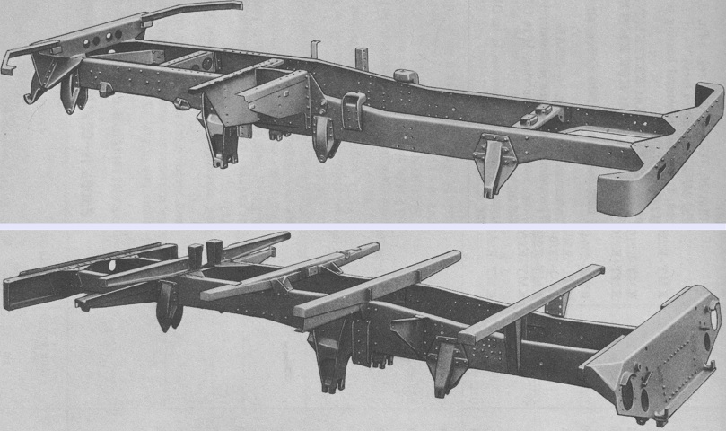
Assembled views of the frames and brackets of the M249 and M250 are provided at the top and bottom, respectively. Both are seen from the front right. (Picture from ORD 9 SNL G-268 List of All Service Parts of Truck, Gun Lifting, Heavy, 4 x 4, Front, M249; Truck, Gun Lifting, Heavy, 4 x 4, Rear, M250.)
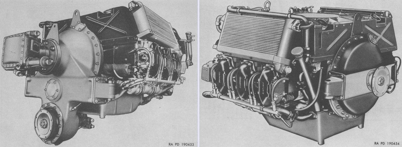
The engines for the M249 and M250 are on the left and right, respectively. The transfer assembly was an integral part of the M249's AO-895-4, spec-3 engine, while the M250's AO-895-4, spec-4 had a separate transfer assembly connected to the engine and power train with propeller shafts. (Picture from ORD 9 SNL G-268 List of All Service Parts of Truck, Gun Lifting, Heavy, 4 x 4, Front, M249; Truck, Gun Lifting, Heavy, 4 x 4, Rear, M250.)
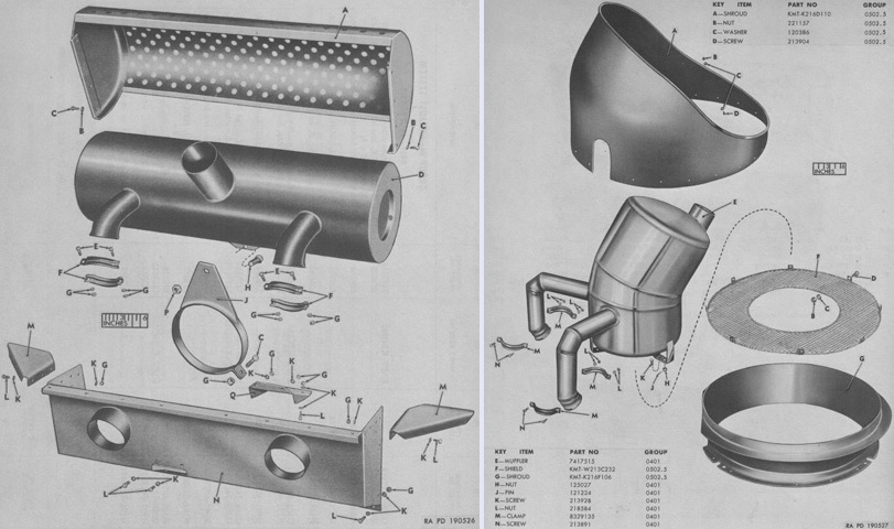
The engine exhaust arrangements for the M249 and M250 are pictured on the left and right, respectively. (Picture from ORD 9 SNL G-268 List of All Service Parts of Truck, Gun Lifting, Heavy, 4 x 4, Front, M249; Truck, Gun Lifting, Heavy, 4 x 4, Rear, M250.)
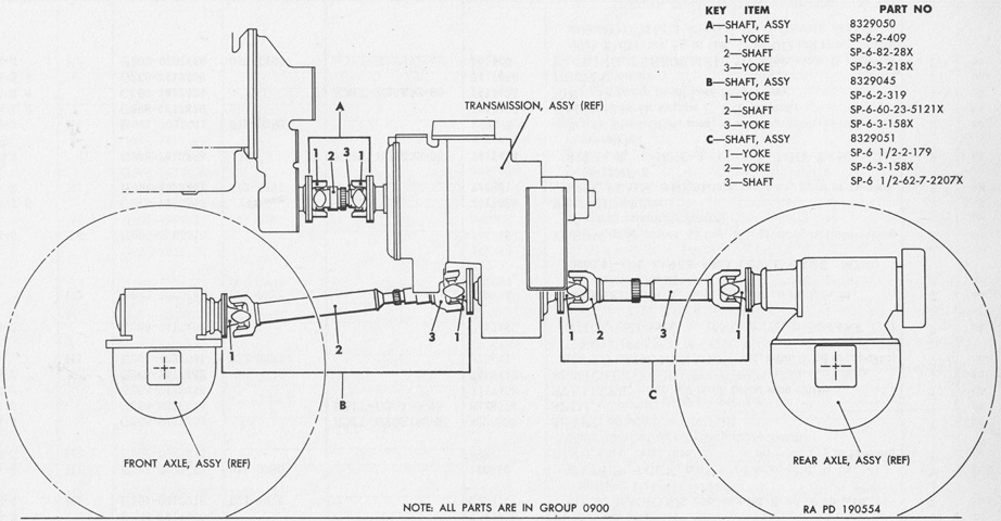
The propeller shaft arrangement of the M249 is drawn above. The engine is at the upper left of the image. (Picture from ORD 9 SNL G-268 List of All Service Parts of Truck, Gun Lifting, Heavy, 4 x 4, Front, M249; Truck, Gun Lifting, Heavy, 4 x 4, Rear, M250.)
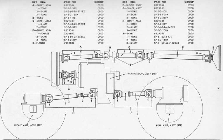
The M250's propeller shafts and pillow blocks can be contrasted with those of the M249. The engine would be to the right of the image connected to flange E. (Picture from ORD 9 SNL G-268 List of All Service Parts of Truck, Gun Lifting, Heavy, 4 x 4, Front, M249; Truck, Gun Lifting, Heavy, 4 x 4, Rear, M250.)
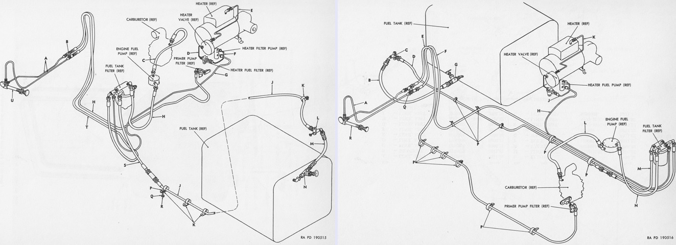
The fuel system of the M249 is sketched on the left, while that of the M250 is on the right. (Picture from ORD 9 SNL G-268 List of All Service Parts of Truck, Gun Lifting, Heavy, 4 x 4, Front, M249; Truck, Gun Lifting, Heavy, 4 x 4, Rear, M250.)
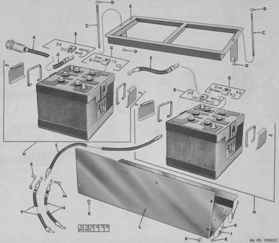
Two 12-volt batteries were used in each truck for the 24-volt electrical system. (Picture from ORD 9 SNL G-268 List of All Service Parts of Truck, Gun Lifting, Heavy, 4 x 4, Front, M249; Truck, Gun Lifting, Heavy, 4 x 4, Rear, M250.)
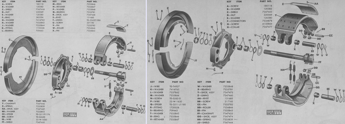
The front right service brake and rear right service brake of the transport units have been exploded in these views on the left and right, respectively. (Picture from ORD 9 SNL G-268 List of All Service Parts of Truck, Gun Lifting, Heavy, 4 x 4, Front, M249; Truck, Gun Lifting, Heavy, 4 x 4, Rear, M250.)
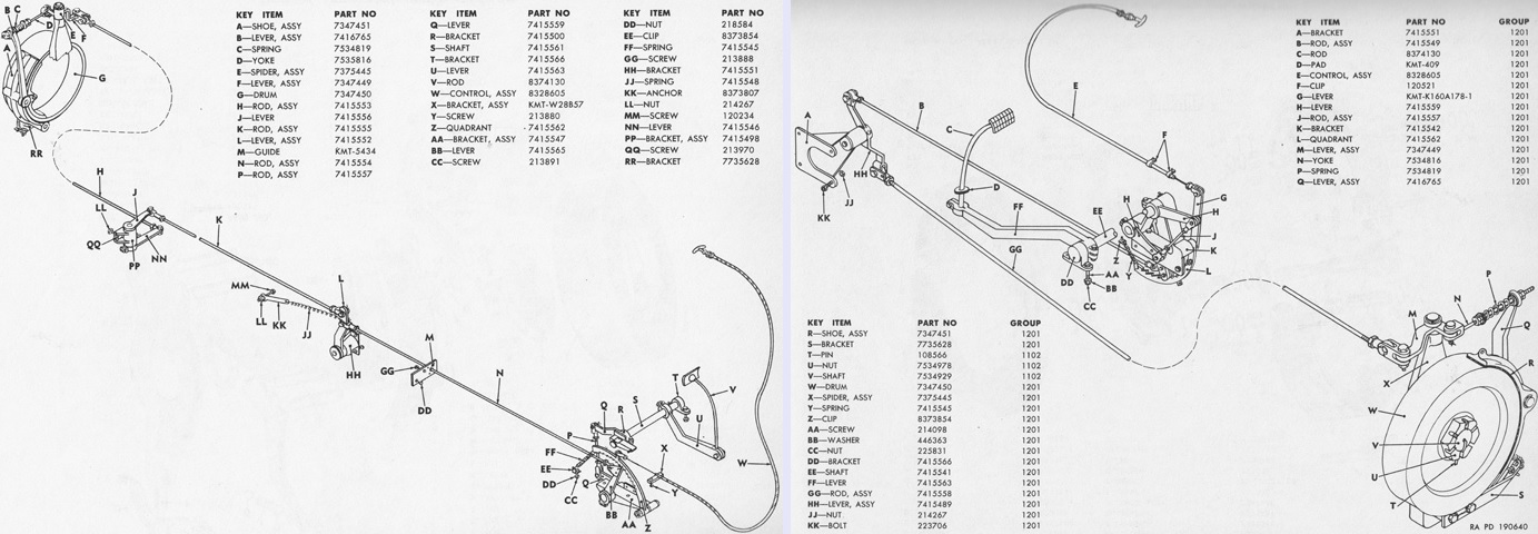
Linkages for the M249's and M250's emergency brakes can be compared on the left and right, respectively. (Picture from ORD 9 SNL G-268 List of All Service Parts of Truck, Gun Lifting, Heavy, 4 x 4, Front, M249; Truck, Gun Lifting, Heavy, 4 x 4, Rear, M250.)
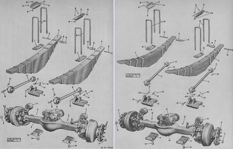
The front axles, springs, torque rods, and mountings for the M249 and M250 can be compared on the left and right, respectively. (Picture from ORD 9 SNL G-268 List of All Service Parts of Truck, Gun Lifting, Heavy, 4 x 4, Front, M249; Truck, Gun Lifting, Heavy, 4 x 4, Rear, M250.)
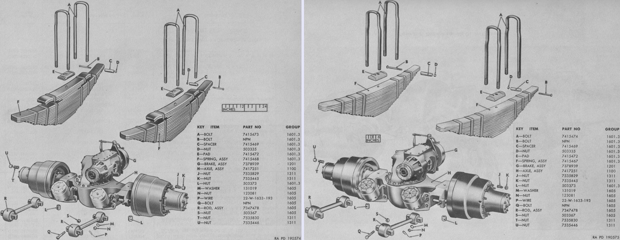
A similar comparison is provided above for the rear axles, springs, torque rods, and mountings for the M249 and M250 on the left and right, respectively. (Picture from ORD 9 SNL G-268 List of All Service Parts of Truck, Gun Lifting, Heavy, 4 x 4, Front, M249; Truck, Gun Lifting, Heavy, 4 x 4, Rear, M250.)
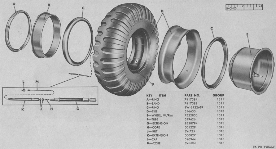
Components of a wheel, tire, and tube are illustrated here. (Picture from ORD 9 SNL G-268 List of All Service Parts of Truck, Gun Lifting, Heavy, 4 x 4, Front, M249; Truck, Gun Lifting, Heavy, 4 x 4, Rear, M250.)
The lifting fork of the M249 was supported on a circular upper and lower mounting plate-type fifth wheel, seen on the left, but the M250's lifting fork was supported on a cylindrical outer fifth wheel that rotated around the vertical axis of the inner fifth wheel, as shown on the right. (Picture from ORD 9 SNL G-268 List of All Service Parts of Truck, Gun Lifting, Heavy, 4 x 4, Front, M249; Truck, Gun Lifting, Heavy, 4 x 4, Rear, M250.)
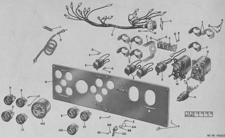
The driver's instrument panel assembly is shown exploded in this view. (Picture from ORD 9 SNL G-268 List of All Service Parts of Truck, Gun Lifting, Heavy, 4 x 4, Front, M249; Truck, Gun Lifting, Heavy, 4 x 4, Rear, M250.)
Each truck was provided with a gasoline-burning personnel heater plumbed into the main engine fuel system. (Picture from ORD 9 SNL G-268 List of All Service Parts of Truck, Gun Lifting, Heavy, 4 x 4, Front, M249; Truck, Gun Lifting, Heavy, 4 x 4, Rear, M250.)
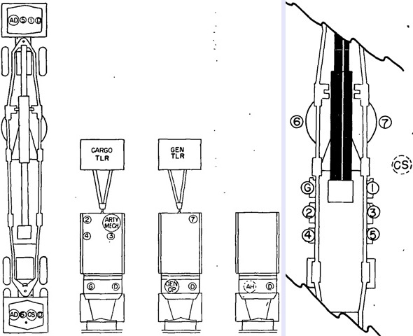
Posts of the gun section are shown mounted on the left and prepared for action on the right. CS is the chief of section; G is the gunner; ARTY MECH is the artillery mechanic; 1-7 are cannoneers, with number 1 serving as the assistant gunner; GEN OP is the off-carriage power generator operator; D are drivers; AD are assistant drivers; and AH is an ammunition handler. Though not listed among the personnel of the gun section itself, an ammunition corporal and two ammunition handlers helped prepare and move ammunition. (Picture from FM 6-96 280-mm Gun T131 on Carriage T72.)
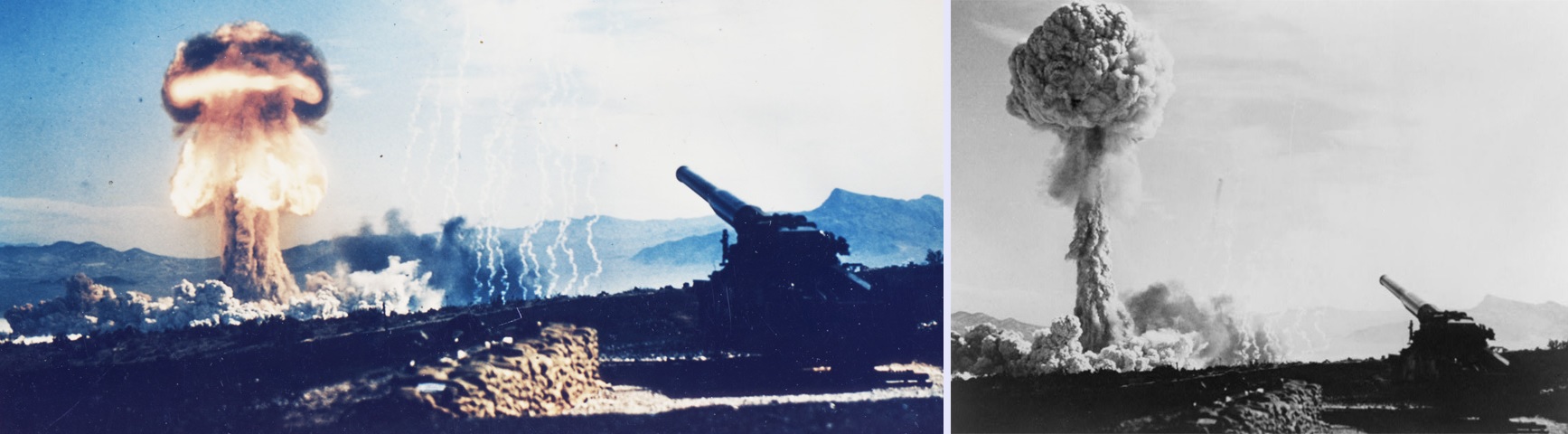
The M66 could fire two types of nuclear artillery shells. Eighty W9 shells were manufactured between April 1952 and November 1953. Using highly enriched uranium, this gun-type fission device was 54.8" (139cm) long and weighed between 803 and 850lb (364 and 386kg). Using a mechanical time delay airburst fuze, it had a 15 kiloton yield. The W9 was replaced on a one-for-one basis by the W19, which began production in July 1955. The W19 was also a gun-type device using highly enriched uranium. It was 54" (137cm) long, weighed 600lb (270kg), and produced a 15-20 kiloton yield. Above are two images of the first nuclear artillery shell test at Frenchman's Flat, Nevada, on 25 May 1953. In the only time the M66 fired a nuclear device, a W9 shell was fired 7 miles (11km) and activated at an altitude of 524' (160m) above the target. (Pictures available from the National Archives and Library of Congress.)
