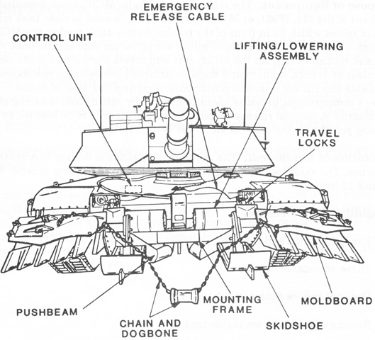
Mine Clearing Blade for M1, IPM1, or M1A1 Abrams Tank.

When pushing the mine clearing blade through a minefield, loose dirt and mines were rolled up onto the moldboards and thence to the sides clear of the tracks. A dogbone weight was suspended by a chain between the left and right moldboards in order to catch tilt rod mines between the tracks. The blade assembly was 115" (292cm) long front to back, 146" (371cm) wide without extensions, 176" (447cm) with extensions, 53" (135cm) high when mounted, and weighed 7,560lb (3,429kg). Ground clearance in travel mode was 16.75" (42.55cm). (Picture from Army TM 9-2590-509-10 Marine Corps TM 2590-10/1.)
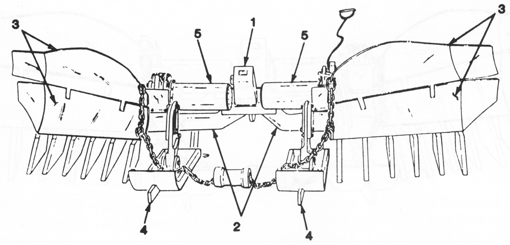
Parts of the blade attachment are detailed in this image. 1. Mounting frame. 2. Pushbeams. 3. Moldboards. 4. Skidshoes. 5. Lifting mechanism. (Picture from Army TM 9-2590-509-23&P Marine Corps TM 2590-23&P/2.)
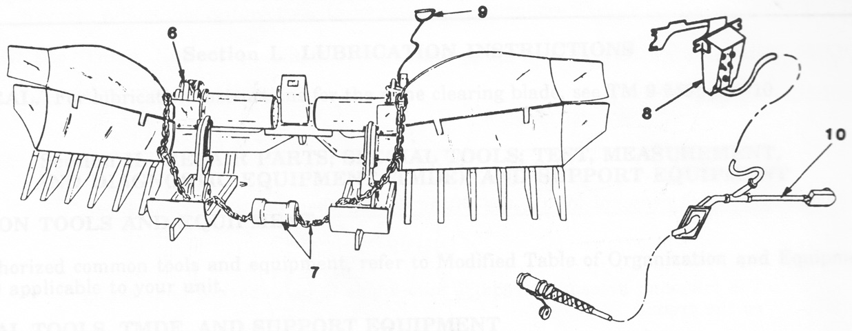
6. Travel locks. 7. Chain and dogbone. 8. Control box. 9. Emergency release cables. 10. Main electrical harness. (Picture from Army TM 9-2590-509-23&P Marine Corps TM 2590-23&P/2.)
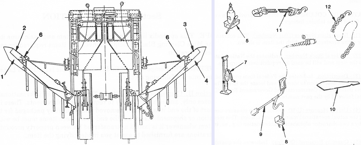
The blade is seen from above in the left image with more components on the right. 1. Moldboard extension bottom R.H. 2. Moldboard extension top R.H. 3. Moldboard extension top L.H. 4. Moldboard extension bottom L.H. 5. Jack assembly. 6. Parking base. 7. Jack, post. 8. Control unit. 9. Main electrical harness. 10. Tine template. 11. Emergency lifting belt. 12. Security chain. (Picture from Army TM 9-2590-509-10 Marine Corps TM 2590-10/1.)
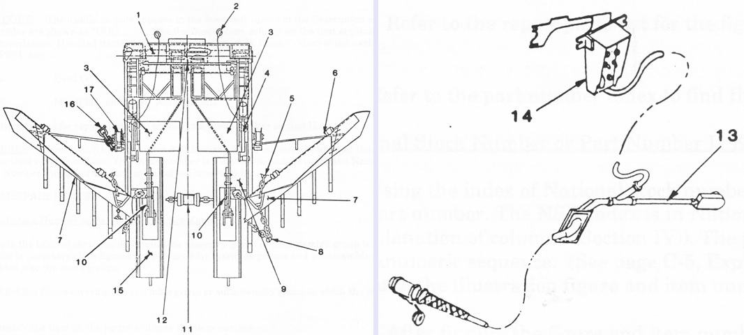
Further details are provided in these images. 1. Mounting frame. 2. Cable, emergency release. 3. Lifting mechanism. 4. Travel lock. 5. Chain, moldboard. 6. Parking support. 7. Moldboard assembly R.H. 7. Moldboard assembly L.H. 8. Preventive chain assembly. 9. Pushbeam, R.H. 9. Pushbeam, L.H. 10. Adjusting plate, R.H. 10. Adjusting plate, L.H. 11. Chain, dogbone. 12. Relay box cover. 13. Main elect harness. 14. Control box assembly. 15. Skidshoe. 16. Chain, limit. 17. Strap, lifting. (Picture from Army TM 9-2590-509-23&P Marine Corps TM 2590-23&P/2.)
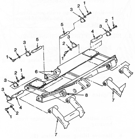
The mounting frame is exploded in this drawing. 1. Screws (18). 2. Lock washers (18). 3. Covers (6). 4. Pins (2). 5. Pins (2). 6. Mounting frame. 7. Pushbeams (2). (Picture from Army TM 9-2590-509-23&P Marine Corps TM 2590-23&P/2.)
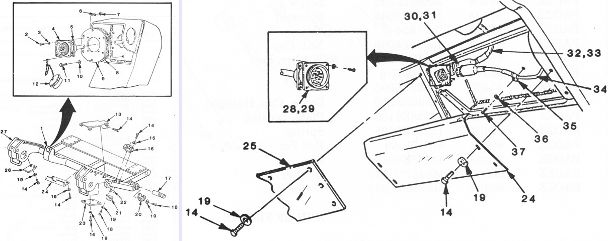
The mounting frame is again diagrammed. 1. Name plate. 2. Screw. 3. Washer. 4. Internal main harness. 5. Gasket. 6. Washer, lock. 7. Nut. 8. Gasket. 9. Flange. 10. Washer, lock. 11. Screw. 12. Cover. 13. Cover top R.H. 13. Cover top L.H. 14. Screw. 15. Washer, lock. 16. Nut, adjusting. 17. Pin, attaching. 18. Screw. 19. Washer, lock. 20. Plate, locking. 21. Fork. 22. Bolt, adjusting. 23. Cover. 24. Cover, access. 25. Relay box cover. 26. Cover. 27. Mounting frame. 28. Elec harness solenoid limit switch left intl. 29. Elec harness solenoid limit switch right intl. 30. Electric wiring motor L.H. 31. Electric wiring motor R.H. 32. Electric harness motor L.H. 33. Electric harness motor R.H. 34. Elec harness solenoid limit switch. 35. Clamp, cable. 36. Washer, lock. 37. Screw. (Picture from Army TM 9-2590-509-23&P Marine Corps TM 2590-23&P/2.)
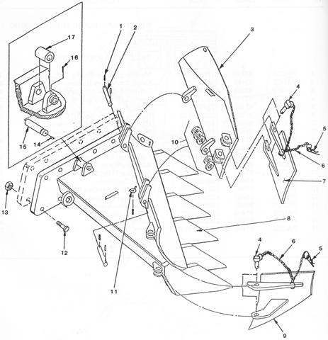
Parts of the moldboard assembly are drawn. 1. Spring pin. 2. Pin. 3. Moldboard, top left. 3. Moldboard, top right. 4. Pin clevis. 5. Hitch pin. 6. Chain assembly. 7. Moldboard extension, top left. 7. Moldboard extension, top right. 8. Moldboard, bottom left. 8. Moldboard, bottom right. 9. Moldboard extension, bottom left. 10. Moldboard extension, bottom right. 11. Nut, plain wing. 12. Screw. 13. Nut, flange. 14. Fitting, lubrication. 15. Pin. 16. Setscrew, hexagon, socket head. 17. Roller. (Picture from Army TM 9-2590-509-23&P Marine Corps TM 2590-23&P/2.)
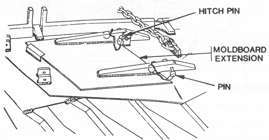
The left top moldboard extension is shown in its stowed position. To remove it from the stowed position, the hitch pin and pin were removed and reinstalled after the extension had been aligned with the moldboard. The mounting lugs for the moldboard extension can be seen at the left of the image. Installing the right top moldboard extension was a similar process. (Picture from Army TM 9-2590-509-10 Marine Corps TM 2590-10/1.)
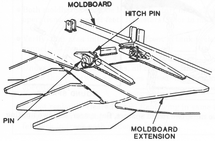
The moldboard extension is installed; the stowage bracket and lugs from the previous image are visible near the top of the drawing. (Picture from Army TM 9-2590-509-10 Marine Corps TM 2590-10/1.)
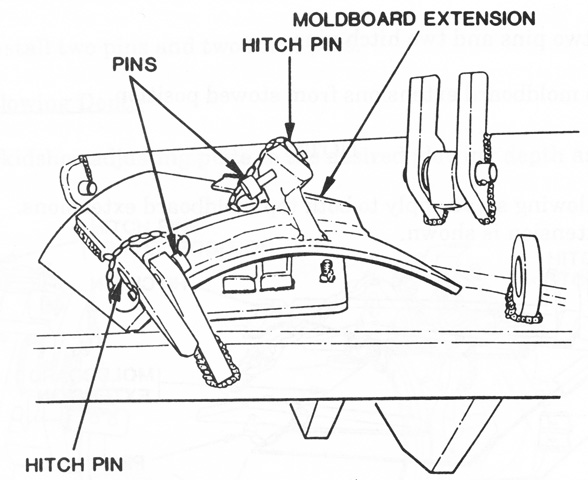
Similarly, the bottom left and right moldboard extensions were secured in their stowed position by hitch pins and pins. The parking support base is visible stowed under the moldboard extension. (Picture from Army TM 9-2590-509-10 Marine Corps TM 2590-10/1.)
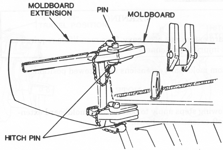
The pins and hitch pins were then used to secure the extensions in their mounted positions. (Picture from Army TM 9-2590-509-10 Marine Corps TM 2590-10/1.)
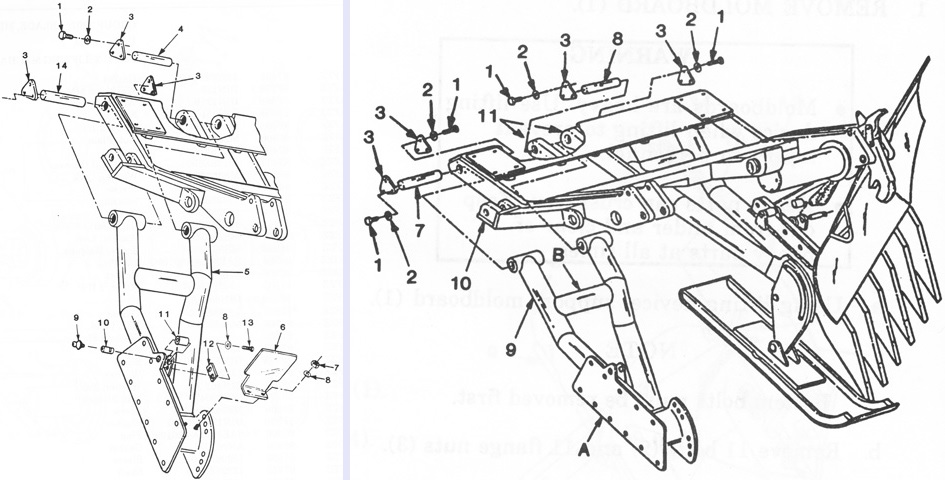
The pushbeam is isolated on the left and drawn with the skidshoe and moldboard assemblies on the right. The legend for the left image is: 1. Screw, cap hexagon. 2. Washer, lock. 3. Cover. 4. Spindle. 5. Pushbeam, right. 5. Pushbeam, left. 6. Guard, splash, right. 6. Guard, splash, left. 7. Nut, plain hexagon. 8. Washer, lock. 9. Fitting, grease. 10. Spindle. 11. Roller, travel lock. 12. Plate, locking. 13. Screw. 14. Spindle.
The legend for the right image is: 1. Screw (12). 2. Lock washer (12). 3. Plate (4). 7. Pin. 8. Pin. 9. Pushbeam. 10. Mounting frame. Points A and B show where lifting devices were to be positioned when mounting the pushbeam. (Picture from Army TM 9-2590-509-23&P Marine Corps TM 2590-23&P/2.)
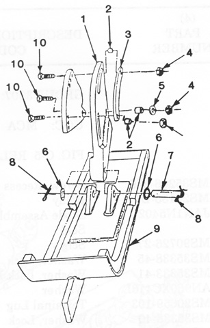
The skidshoe assembly is diagrammed in this exploded sketch. 1. Adjusting plate left. 1. Adjusting plate right. 2. Sleeve. 3. Spacer. 4. Nut, plain hexagon. 5. Washer. 6. Washer, flat. 7. Pin. 8. Pin, cotter. 9. Skidshoe. 10. Screw, cap hexagon. (Picture from Army TM 9-2590-509-23&P Marine Corps TM 2590-23&P/2.)
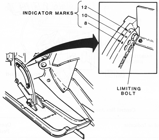
The skidshoes rode along the surface of the ground and limited the moldboard's plowing depth. The plowing depth could be adjusted to 8" (20cm), 10" (25cm), or 12" (30cm) using the limiting bolts on the skidshoes. (Picture from Army TM 9-2590-509-10 Marine Corps TM 2590-10/1.)
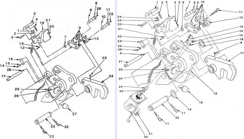
Two exploded views of the travel lock are drawn. The legend for the left image is: 1. Pin. 2. Washer. 3. Pin. 4. Spring. 5. Link. 6. Cotter pin. 7. Washer. 8. Pin. 9. Washer (4). 10. Cotter pin. 11. Pin. 12. Spring (2). 13. Link (2). 14. Screw (2). 15. Washer (2). 16. Plate. 17. Pin. 18. Lever release. 19. Pin. 20. Screw. 21. Nut. 22. Hitch pin. 23. Pin. 24. Travel lock. 25. Nut. 26. Washer. 27. Bumper. 28. Grease fitting (4).
The legend for the right image is: 1. Link. 2. Spring. 3. Lever, release, LH. 3. Lever, release, RH. 4. Nut, plain. 5. Screw, adjusting. 6. Washer. 7. Pin, cotter. 8. Pin. 9. Fitting, lubrication. 10. Washer. 11. Pin, lock. 12. Link. 13. Electrical harness, solenoid limit switch. 14. Nut, plain. 15. Washer, lock. 16. Washer. 17. Travel lock. 18. Frame, mounting. 19. Bumper. 20. Pin. 21. Screw. 22. Solenoid. 23. Nut. 24. Nut, cap. 25. Washer, lock. 26. Nut. 27. Pin. 28. Screw, cap, hexagon. 29. Plate, locking. 30. Spring. 31. Roll pin. 32. Pin. 33. Washer. 34. Cotter pin. (Picture from Army TM 9-2590-509-23&P Marine Corps TM 2590-23&P/2.)
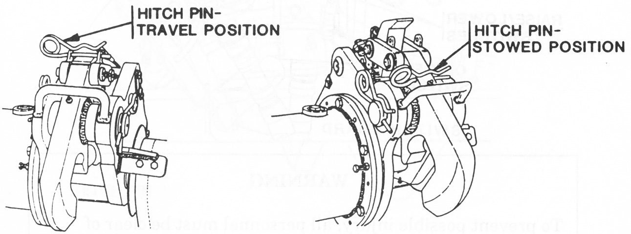
The travel locks were manually released by removing the hitch pin from the travel position, which was then secured in the stowed position. When the moldboards were raised and locked, the pin was reinserted into the travel position (Picture from Army TM 9-2590-509-10 Marine Corps TM 2590-10/1.)
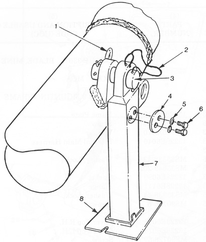
The parking support is drawn deployed. When the blade was mounted to the tank, the parking support was raised alongside the pushbeam to which it was attached, and the base was stowed on the rear of the moldboard. 1. Hitch pin. 2. Chain assembly. 3. Pin. 4. Cover, support. 5. Washer, lock. 6. Screw. 7. Parking support. 8. Parking base. (Picture from Army TM 9-2590-509-23&P Marine Corps TM 2590-23&P/2.)
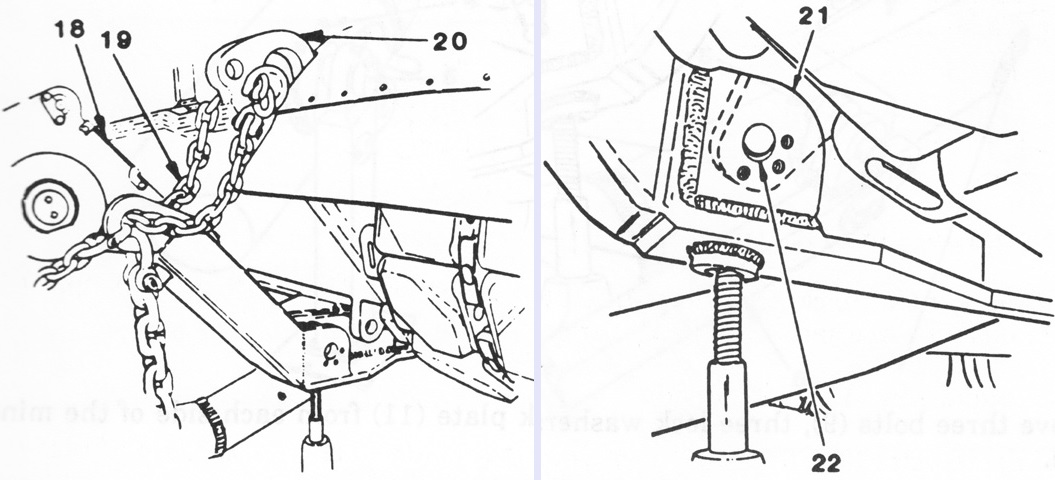
Installation involved attaching the frame to the tank's front hull tow lugs after the shackles were removed. The blade was supported during this process by two hydraulic jacks and one post jack. In the left image, the blade assembly is supported on its jacks while the tank is moved slowly forward until the towing lugs were 5-6" (13-15cm) from the open slots in the blade assembly's mounting frame (18). At this point, safety chains (19) secured the frame to the upper towing lugs (20). On the right, the tank is then moved forward until the bottom towing lugs (21) aligned with the slots (22) of the mounting frame. (Picture from Army TM 9-2590-509-23&P Marine Corps TM 2590-23&P/2.)
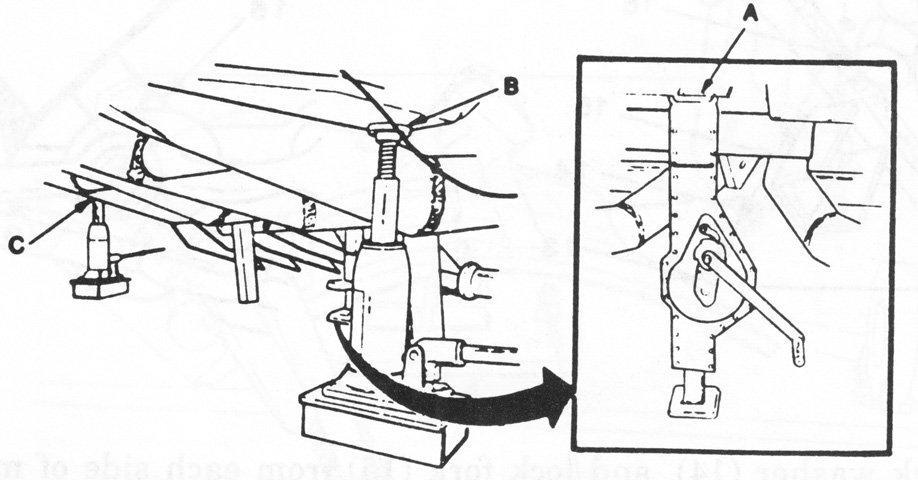
Once the towing lugs were in line with the mounting frame slots, the hydraulic jacks (B and C) and post jack (A) were used to raise the frame so it could be secured to the lugs. (Picture from Army TM 9-2590-509-23&P Marine Corps TM 2590-23&P/2.)
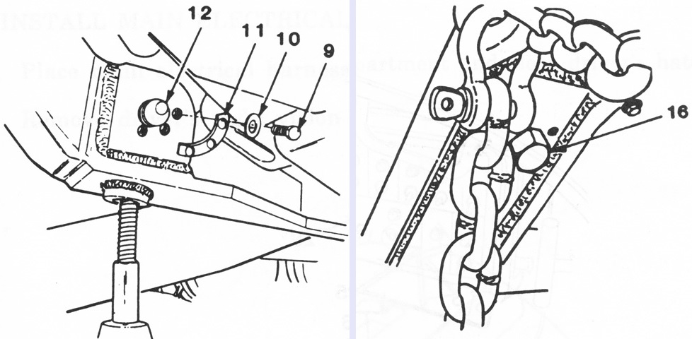
After the holes in the lugs and frame were aligned, the attaching pin (12) on each side was inserted from the inside, and the three bolts (9) and lock washers (10) were installed in the lock plate (11) on each side of the blade. The post jack could then be removed, and the adjusting bolts (16) tightened against the tank hull. The hydraulic jacks could then also be taken away. (Picture from Army TM 9-2590-509-23&P Marine Corps TM 2590-23&P/2.)
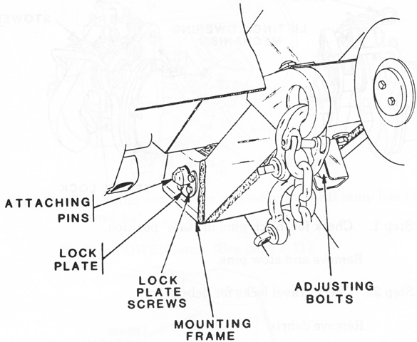
The installed mounting frame is sketched above. (Picture from Army TM 9-2590-509-10 Marine Corps TM 2590-10/1.)
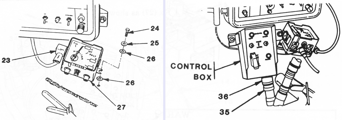
The control box was installed on a bracket in the driver's compartment. His intercom junction box (27) was dismounted, and its plug (23) removed. The screws (24), washers (25), and star washers (26) were reused to secure the junction box to the mine blade control box. On the right, the mine blade control box connector (36) is plugged into the electrical harness connector (35), and the junction box can be seen hanging from the control box bracket. (Picture from Army TM 9-2590-509-23&P Marine Corps TM 2590-23&P/2.)
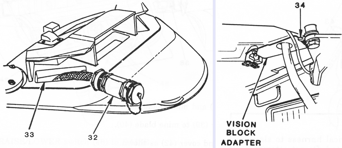
No drilling or welding of the tank hull was necessary for the blade's installation. The electrical harness (32) was routed to the control box through the driver's right periscope port (33) using an adapter secured by two wingnuts (34). The electrical harness also connected to the blade and to the tank's slave start socket, from which the required 24 volt DC power was drawn. (Picture from Army TM 9-2590-509-23&P Marine Corps TM 2590-23&P/2.)
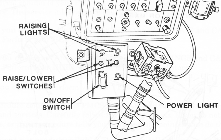
The control box assembly contained an on/off switch as well as left and right raising/lowering switches. Each raising/lowering switch powered an identical electrical motor on each side of the blade. The raising lights would illuminate when the blade was being raised, and would extinguish when it was fully raised. It took 2 seconds to lower the blade from the travel position to the plowing position. If the moldboards failed to lower using the control box, the manual release cables could be pulled. (Picture from Army TM 9-2590-509-10 Marine Corps TM 2590-10/1.)
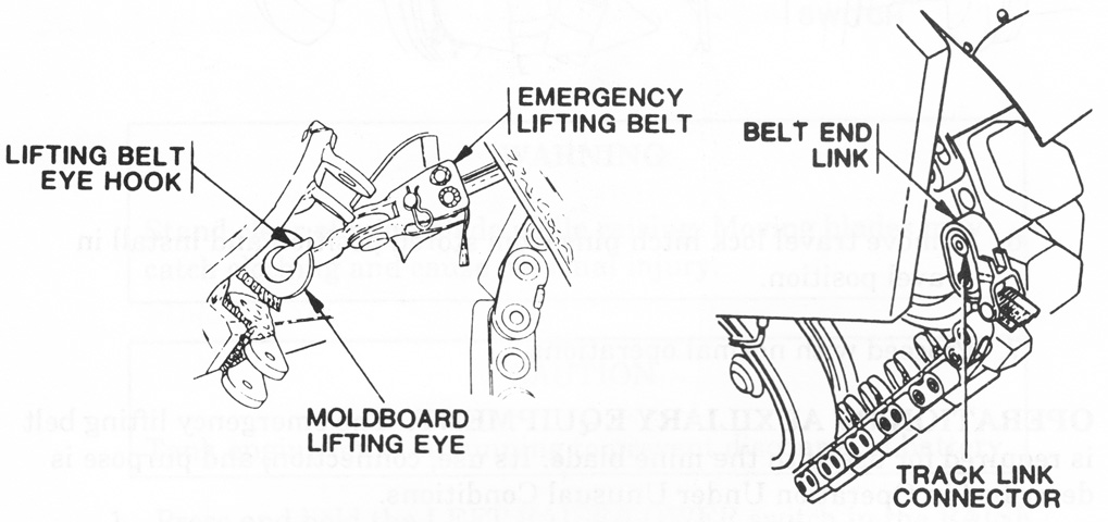
If the electrical system failed with the blade deployed, an emergency lift system was provided to get the blade back into the travel position. The emergency lifting belt was hooked to the moldboard's lifting eye, and the belt's end link was then secured to an end connector of the tank's track. The tank was then reversed a short distance until the moldboard could be locked into the travel position. (Picture from Army TM 9-2590-509-10 Marine Corps TM 2590-10/1.)
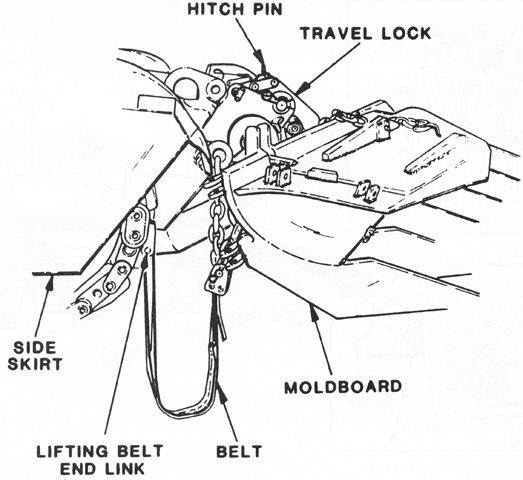
In this sketch, the blade has been stowed and the tank driven forward until the belt could be detached from the track end connector. (Picture from Army TM 9-2590-509-10 Marine Corps TM 2590-10/1.)
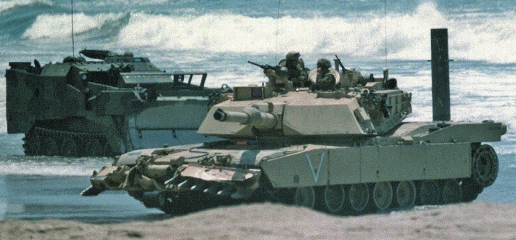
The mine clearing blade is seen in the travel position as this tank of the 1st Marine Division participates in a beach assault during Exercise KERNEL BLITZ. Wading equipment is in place on the tank, and an armored combat earthmover M9 is in the background. (Picture taken 24 April 1999 by LCpl Michael A. Gardner; available from the National Archives.)
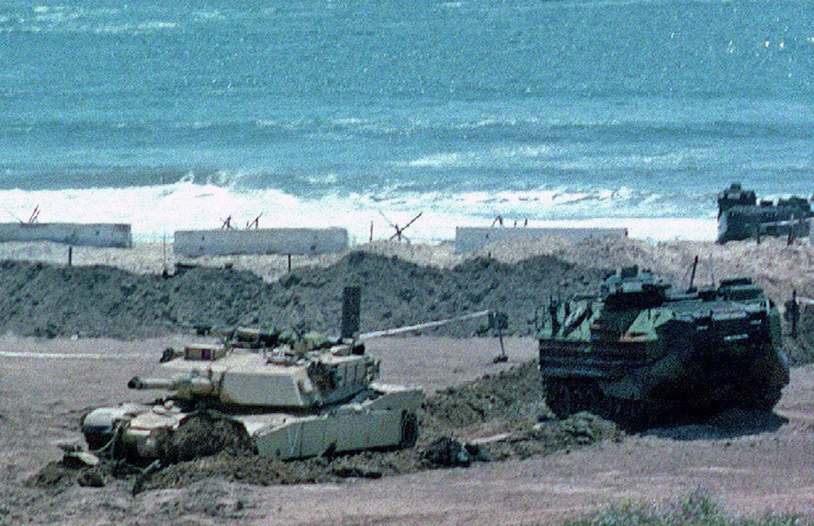
The mine clearing blade has been lowered and has started plowing a path through the beach. The tank could move 8-10mph (13-16kph) while plowing, and the moldboards were to be lowered at least 32' (9.8m) prior to the minefield. Similarly, plowing was to continue for that same distance beyond the minefield. When plowing was finished, the tank was to be reversed ~6' (~1.8m) before raising the moldboard so that the tines were removed from the earth. AAVP7A1 amphibious tractors are behind the tank. (Picture taken 24 April 1999 by MSgt Edward Aspera, Jr.; available from the National Archives.)