Armored Combat Earthmover M9.
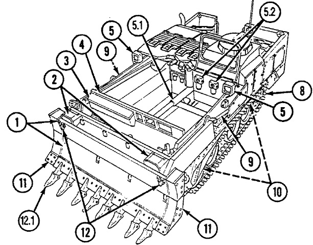
This overhead view provides a look into the scraper bowl. 1. Apron and dozer assembly. 2. Headlights. 3. Stowage box. 4. Ejector. 5. Floodlights. 5.1. Debris shield. 5.2. High-pressure filters. 8. Track. 9. Apron cylinder. 10. Track wear plates. 11. Apron and dozer extensions. 12. Dozer/ripper blade latches. 12.1. Ripper blade.
The ejector moved back and forth in the bowl to discharge material, load or unload palletized cargo, and fold the dozer blade. The debris shield protected the hose assemblies and fittings in the lower bowl area. The apron cylinder raised or lowered the apron and dozer assembly. The apron and dozer extensions could be removed for transport, and similarly the dozer/ripper blade latches locked the dozer/ripper blade into the folded position for travel. The vehicle width with the dozer extensions was 125" (318cm). (Picture from TM 5-2350-262-10 C-7.)
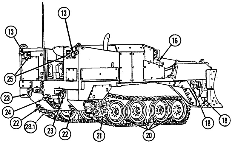
The rear of the machine is drawn here. 13. Rear floodlights. 16. Upper apron lockpins. 18. Dozer lockpins. 19. Tiedown shackles. 20. Roadwheels. 21. Sprockets. 22. Tiedown brackets. 23. Tow shackles. 23.1. Hull protective plates. 24. Towing pintle. 25. Taillights. (Picture from TM 5-2350-262-10 C-7.)
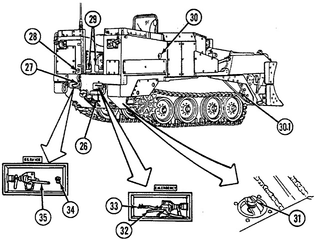
26. Rear step. 27. Winch assembly. 28. Trailer electrical receptacle. 29. Liquid container brackets. 30. External fire extinguisher handle. 30.1. Track retainers. 31. Hull drain valve. 32. Trailer emergency brake air coupling. 33. Fuel drain valve. 34. Air reservoir drain valve. 35. Trailer brake coupling.
The track retainers helped keep the tracks on the sprockets when the suspension was lowered for earthmoving operations. (Picture from TM 5-2350-262-10 C-7.)
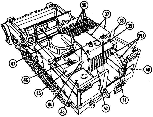
36. Intake grilles. 37. Access covers. 38. Muffler. 39. Antenna. 39.1. Battery box deflectors. 40. Slave receptacle. 41. Battery box. 42. Exhaust grilles. 43. Fuel tank. 44. Hydraulic oil fill port. 45. Radio box. 46. Hatch cover latch. 47. Driver's hatch assembly.
The battery box deflectors directed hot air from the radiators away from the batteries. (Picture from TM 5-2350-262-10 C-7.)
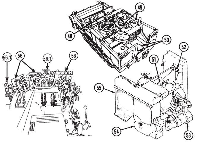
The powertrain and driver's compartment are included in this sketch. 48. Smoke grenade launchers. 49. Fixed fire extinguisher system. 50. Rear floor plates. 51. Engine. 52. Engine cold start system. 53. Transfer case. 54. Transmission. 55. Radiator. 56. Driver's controls and indicators. 56.1. Inclinometers. (Picture from TM 5-2350-262-10 C-7.)
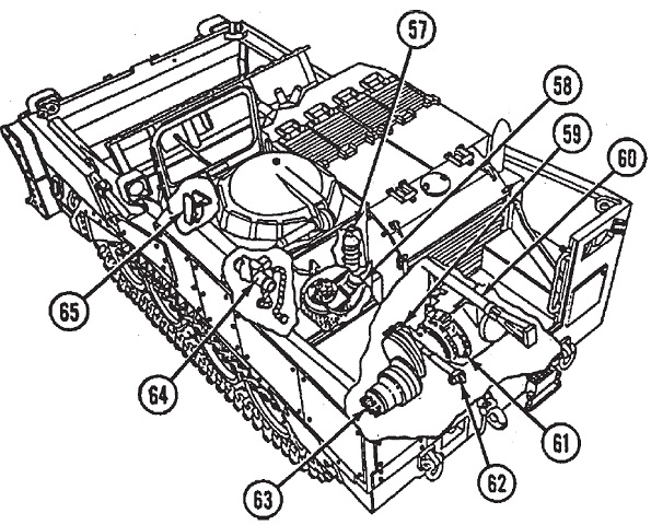
Some interior components are shown here. 57. Portable fire extinguisher. 58. Bilge pump. 59. Fuel shut-off valve. 60. Ejector cylinder. 61. Steer unit. 62. Track adjusting cylinder. 63. Final drives. 64. NBC installation. 65. Bump stops (retractable). (Picture from TM 5-2350-262-10 C-7.)
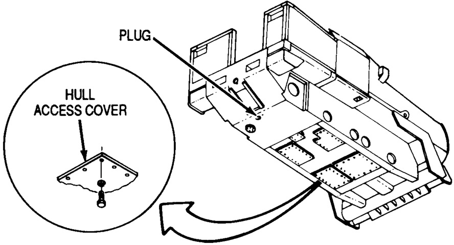
Access covers and drain plugs on the hull bottom can be seen in this drawing. (Picture from TM 5-2350-262-20-1 C-4.)
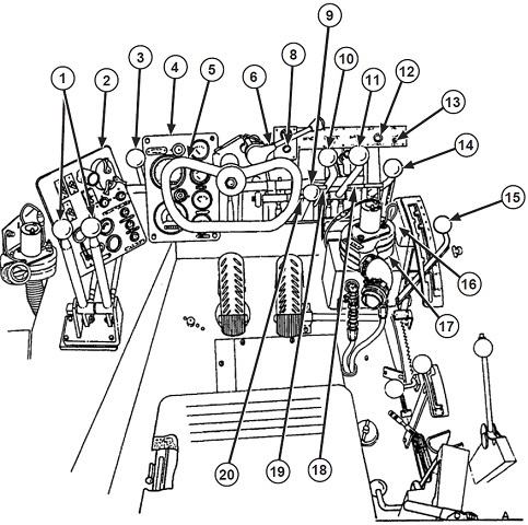
The operator's controls are sketched here. 1. Suspension control levers (left and right). 2. Switch panel. 3. Suspension SPRUNG/UNSPRUNG lever. 4. Gage panel. 5. Steering wheel. 6. Trailer brake control. 8. Start aid control button. 9. Winch control lever. 10. Ejector control lever. 11. Apron control lever. 12. Domelight dimmer switch. 13. Bilge pump light. 14. Bilge pump lever. 15. Transmission shift lever. 16. Warning buzzer. 17. Personnel heater. 18. Bilge pump stop lock. 19. Ejector stop lock. 20. Winch stop lock.
The start aid control button injected fuel into the engine intake to aid starting in cold weather. Though no clutch pedal was required, the transmission speeds were selected manually. (Picture from TM 5-2350-262-10 C-7.)
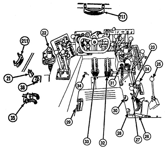
21. Arming firing unit. 21.1. Inclinometer. 22. Ventilation fan. 23. Hand throttle. 24. CB/GS steer selector lever. 25. Winch shift lever. 26. Hatch cover release. 27. Hand brake lever. 28. Seat vertical adjusting lever. 29. Seat horizontal adjusting lever. 30. Hydraulic oil reservoir filler and dipstick. 31. Heater control valve. 32. Accelerator pedal. 33. Brake pedal. 34. Headlight beam selector switch. 35. NBC system air heater. 36. Air purifier switch.
The arming firing unit controlled the smoke grenade launcher system. The CB/GS steer selector lever switched between clutch-brake or geared steering. Clutch-brake was to be used when driving in close quarters and at low speeds. Geared steering was automatically selected when the transmission selector was moved into 5th or 6th gear, while clutch-brake was automatically selected when the transmission was moved into either of the reverse gears. (Picture from TM 5-2350-262-10 C-7.)
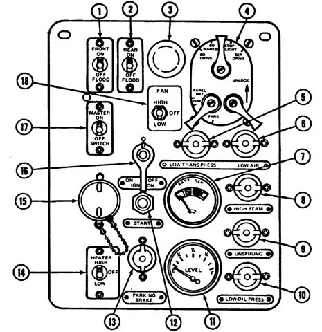
The driver's switch panel is detailed in this drawing. 1. Floodlight switch (front). 2. Floodlight switch (rear). 3. Panel light. 4. Light switch assembly. 5. Low transmission oil pressure indicator light. 6. Low brake system air pressure indicator light. 7. Battery/generator indicator. 8. High beam indicator light. 9. Unsprung indicator light [lights when suspension is in unsprung mode and transmission is in reverse]. 10. Low engine oil pressure indicator light. 11. Fuel level indicator. 12. Start switch. 13. Parking brake indicator light. 14. Heater switch. 15. Utility outlet. 16. Ignition on/off switch. 17. Master switch. 18. Fan switch. (Picture from TM 5-2350-262-10 C-7.)
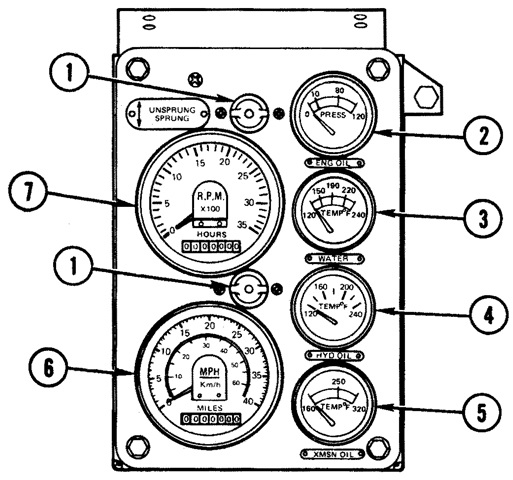
The driver's gage panel is detailed here. 1. Panel lights. 2. Engine oil pressure indicator. 3. Water temperature indicator. 4. Hydraulic oil temperature indicator. 5. Transmission oil temperature indicator. 6. Speedometer. 7. Tachometer/hourmeter. (Picture from TM 5-2350-262-10 C-7.)
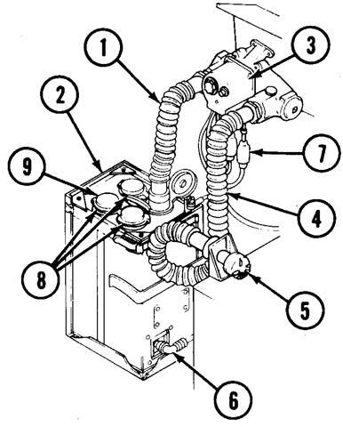
The operator was provided with a gas particulate system composed of a gas particulate filter unit M2A2, an air heater M3, and a chemical-biological mask M25A1. The system would not protect against carbon monoxide. The operator's protective mask was connected to the system via hose assembly 4 in the diagram, after disconnecting it from connector 5. 1. Hose assembly. 2. Gas-particulate filter unit. 3. Air heater. 4. Hose assembly. 5. Connector. 6. Electrical connector. 7. Electrical lead (3). 8. Quick-disconnect outlet (4). 9. Flow control cap. (Picture from TM 5-2350-262-10 C-7.)
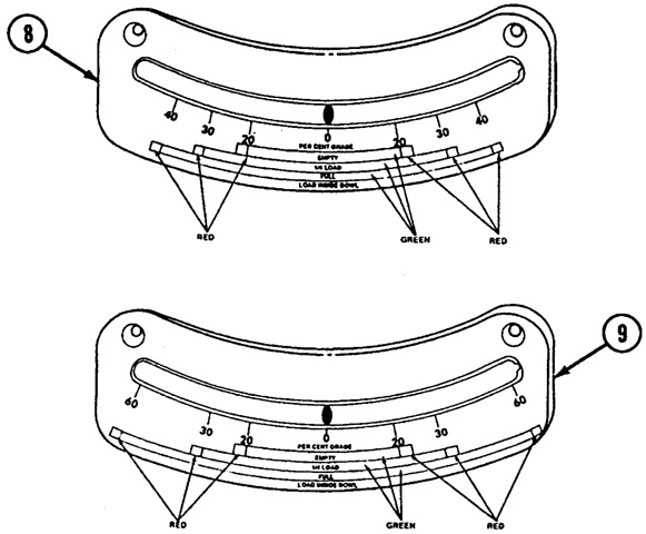
The front (8) and side (9) inclinometers showed the grades that were safe based on different loads carried in the bowl. (Picture from TM 5-2350-262-10 C-7.)
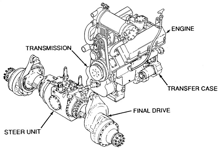
The vehicle's powertrain is shown here. The engine displaced 903in³ (14.8L). The steer unit used either geared steering or clutch-brake steering, depending on the selection of the transmission gear and/or the steering mode selector. The steer unit also provided braking for the vehicle via an air-operated brake chamber. (Picture from TM 5-2350-262-20-1 C-4.)
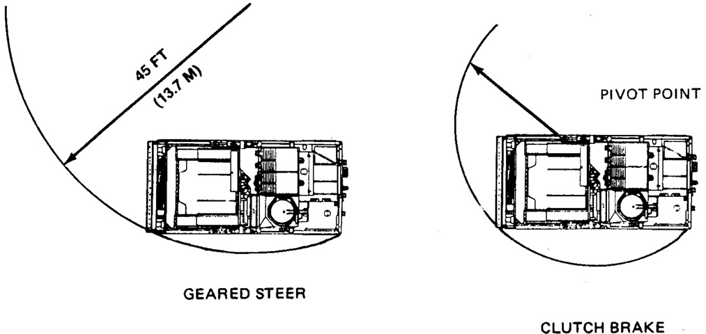
The smallest turning radii are illustrated when the vehicle is in geared steer versus clutch brake steer modes. (Picture from TM 5-2350-262-10 C-7.)
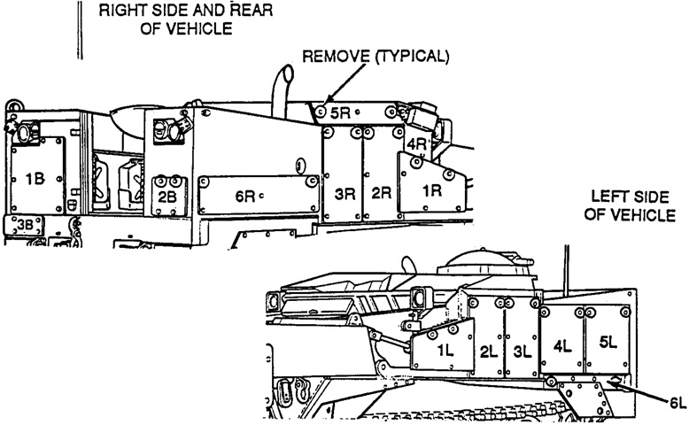
Fifteen armor plates were attached to the exterior, and they are labeled here. The circled screws/washers/lockwashers in the drawings show which fasteners were necessary to remove first when taking off the plates. If the vehicle was transported on C-130 or C-141 aircraft, plates 4R and 5R were required to be dismounted. (Picture from TM 5-2350-262-10 C-7.)
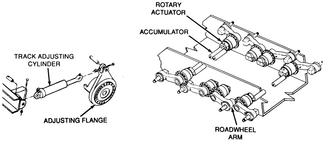
The sprung suspension mode was used during normal driving, which allowed rotation of the rotary actuators in response to terrain. Accumulators attached to the front and rear actuators served as shock absorbers as fluid was forced into them by the actuators' rotation. When using unsprung mode, the rotation of the actuators was controlled by the driver to adjust the vehicle's attitude as needed for scraping or dozing requirements. The front actuators were the ones that allowed the vehicle to raise and lower in unsprung mode; interwheel control valves in the intermediate two actuators on each side allowed those wheels to follow the outer actuators when the vehicle was lowered; while the rear actuators were unable to be raised or lowered. Due to the risk of throwing a track when reversing in unsprung mode, sharp turns in reverse were only to be made when the suspension was in sprung mode. If not equipped with the hydraulic blade folder-track tensioner system, track tension was adjusted via track adjusting cylinders accessible under the rear floor plates. These moved the position of the drive sprockets via flanges on the final drive units. (Picture from TM 5-2350-262-20-1 C-4.)
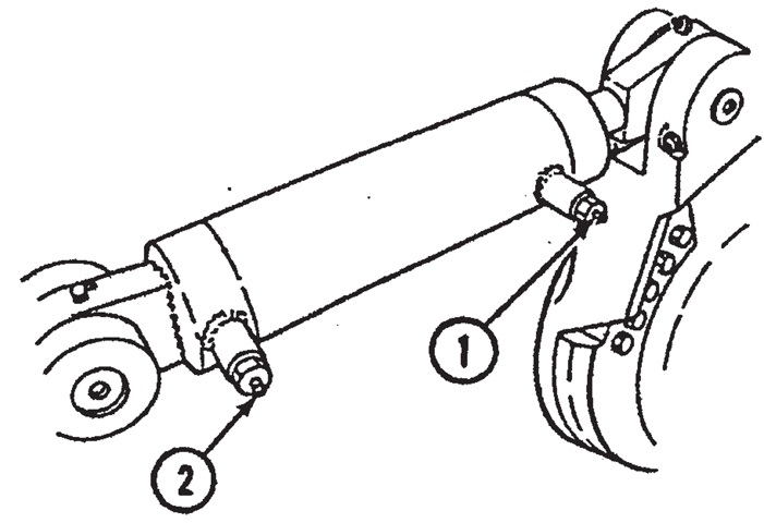
Track tension could be lessened by loosening the rear fill valve (2) and pumping grease into the front fill valve (1). When tightening track tension, the procedure was reversed. (Picture from TM 5-2350-262-10 C-7.)
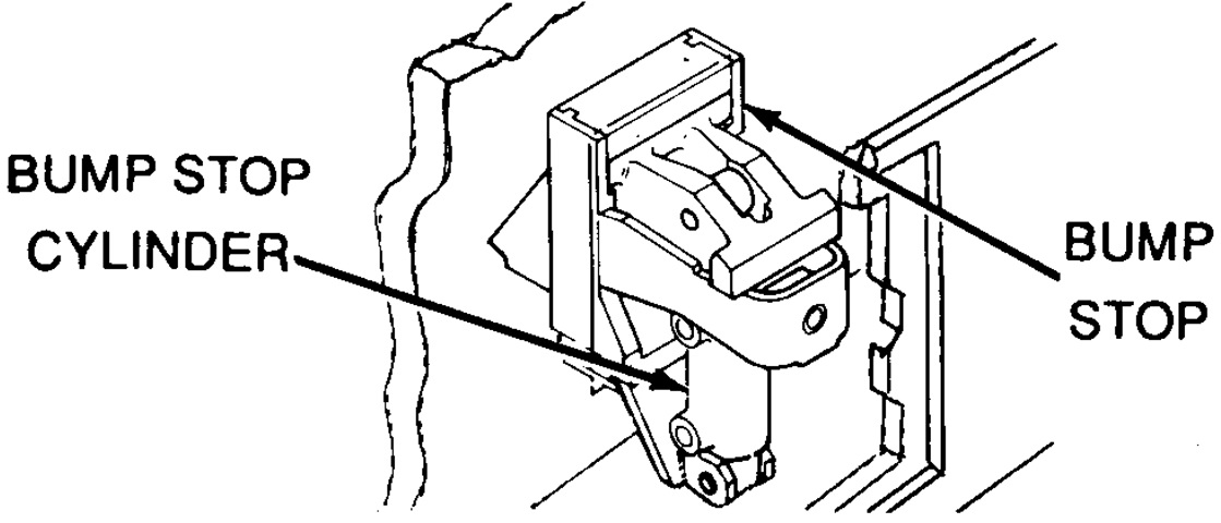
Bump stops were found above the front road wheel arms. When operating in unsprung mode, the bump stops were hydraulically retracted into the hull by the bump stop cylinders. (Picture from TM 5-2350-262-20-1 C-4.)
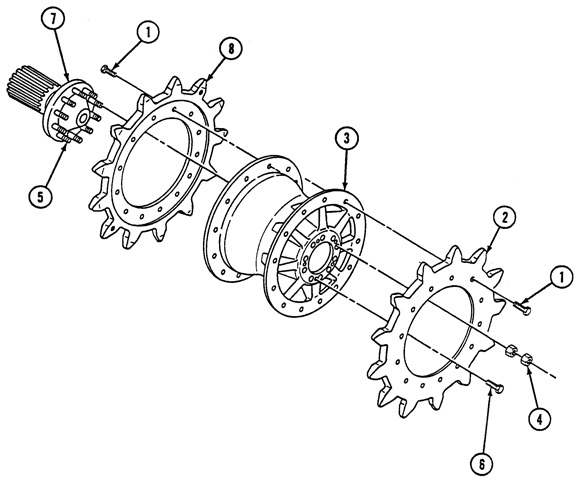
An exploded view of the drive sprocket can be seen here. 1. Self-locking screws (13). 2. Outer sprocket. 3. Hub. 4. Locknuts (20). 5. Studs. 6. Jacking screws (5) [self-locking screws from item 1 that were retained to lever hub from final drive]. 7. Final drive. 8. Inner sprocket. (Picture from TM 5-2350-262-20-2 C-4.)
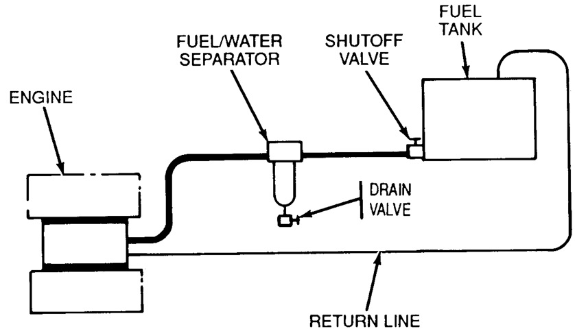
A schematic of the fuel system is shown here. (Picture from TM 5-2350-262-20-1 C-4.)
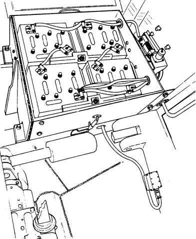
The battery box is drawn with the cover removed. Four 12-volt lead-acid batteries were connected in series-parallel to provide for the 24-volt electrical system. Each battery weighed 72lb (33kg). (Picture from TM 5-2350-262-20-1 C-4.)
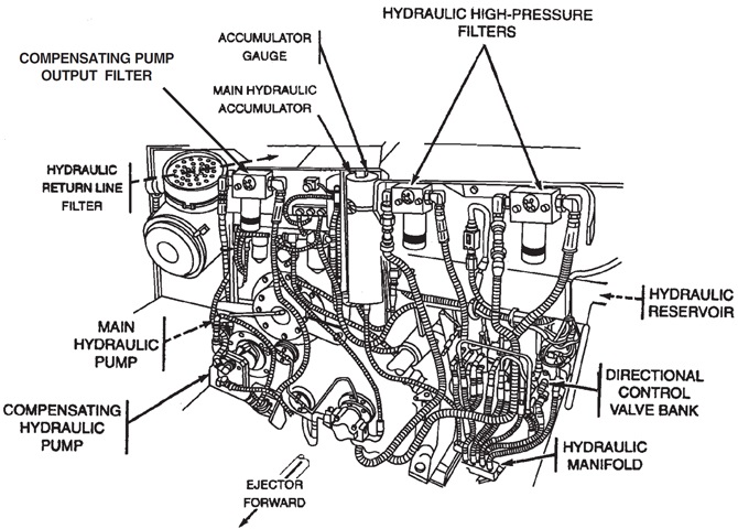
The hydraulic system is sketched in this picture. The variable displacement compensating hydraulic pump provided a constant 2,850psi (200kg/cm²) pressure to the sprung/unsprung hydraulic operation. The main hydraulic accumulator was charged with nitrogen to 1,800psi (130kg/cm²) at 70°F (20°C) to provide immediate response to the sprung mode should the compensating pump be unable to meet demand. The hydraulic reservoir had a capacity of 32gal (120L). (Picture from TM 5-2350-262-20-1 C-4.)
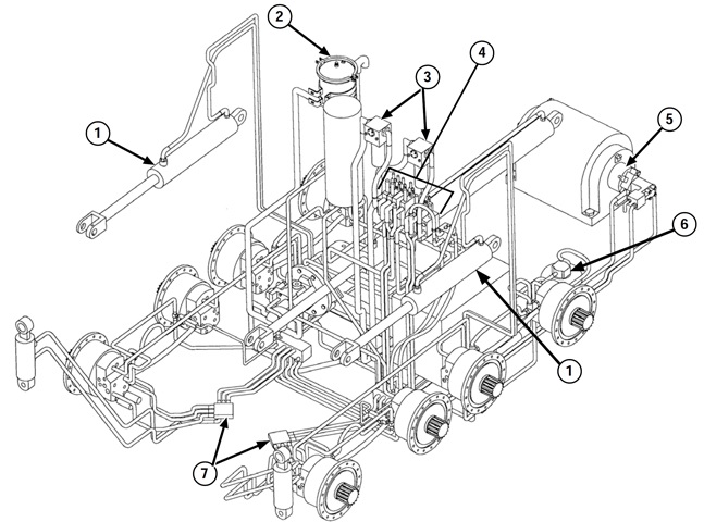
A schematic of the hydraulic system is provided in this image. 1. Apron cylinder. 2. Return line filter. 3. High pressure filters. 4. Directional control valve. 5. Winch motor. 6. Bilge pump motor [considered Not Mission Essential and not supported by spare or repair parts since at least March 2007]. 7. Forward manifold. (Picture from TM 5-2350-262-20-3 C-2.)
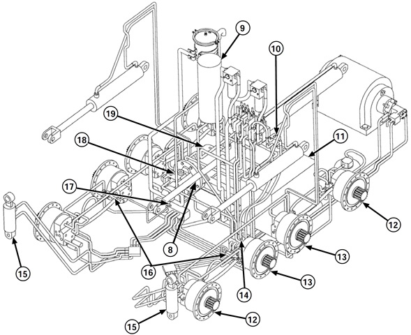
8. Ejector cylinder. 9. Main accumulator. 10. Sprung/unsprung valve. 11. Hydraulic reservoir. 12. No. 1 and 4 actuators. 13. No. 2 and 3 actuators. 14. Suspension relief valve. 15. Bump stop cylinders. 16. Intermediate wheel valve. 17. Check valve. 18. Compensating pump. 19. Main hydraulic pump. (Picture from TM 5-2350-262-20-3 C-2.)
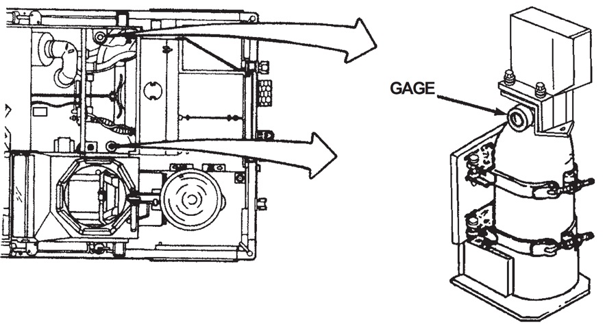
Two fixed fire extinguishers were mounted in the locations shown. (Picture from TM 5-2350-262-10 C-7.)
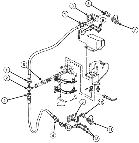
The mounting of the left-side fire extinguisher can be seen here. The right-side extinguisher mounting was similar. 1. Hose assembly. 2. Tube tee. 3. Fire extinguisher bracket. 4. Hose assembly. 5. Fire extinguisher bracket. 6. Adapter. 7. Discharge nozzle. 8. Elbow. 9. Screws. 10. Washers. 11. Discharge nozzle. 12. Elbow. 13. Screws. 14. Washers. (Picture from TM 5-2350-262-20-1 C-4.)
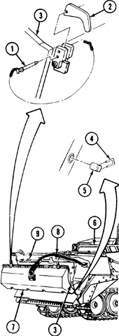
It was possible to fold the blade back against the apron when driving for long periods over uneven terrain, entering or leaving water via a steep bank, or when more ground clearance was required. Vehicles could be equipped with an hydraulic blade folder-track tensioner system, or the procedure could be accomplished using a chain attached to the lifting eye on the ejector, as shown here. The vehicle was 243" (617cm) long in this configuration. 1. Pin assembly. 2. Dozer blade latch. 3. Apron. 4. Clip. 5. Dozer blade lockpin. 6. Ejector. 7. Dozer blade. 8. Chain. 9. Shovel. (Picture from TM 5-2350-262-10 C-7.)
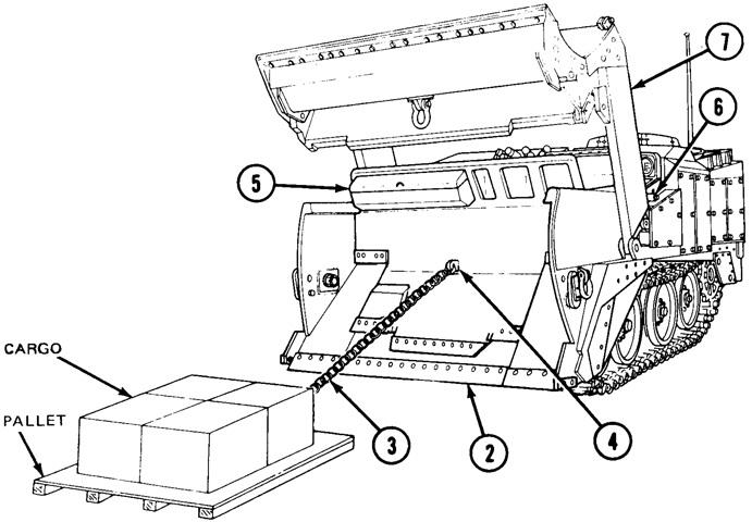
Palletized cargo could be transported in the bowl.The procedure for loading the pallet involved attaching it to the ejector via a chain and then retracting the ejector. 2. Scraper cutting edge. 3. Chain. 4. Lifting eye. 5. Ejector. 6. Apron lockpin. 7. Apron. (Picture from TM 5-2350-262-10 C-7.)
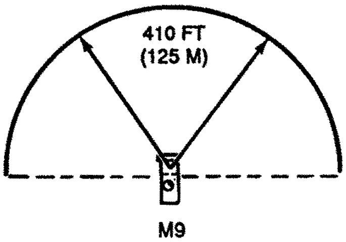
The range of the smoke grenades is sketched here. (Picture from TM 5-2350-262-10 C-7.)
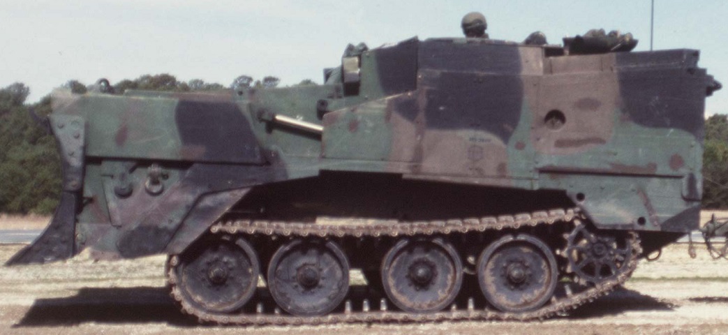
The flat track suspension of the M9 is obvious here; it could be adjusted to alter the striking angle of the dozer blade. The blade could be raised to allow the scraper bowl to be filled to increase the weight of the vehicle. (Picture taken 1 Jan 1997; available from the Defense Visual Information Center.)
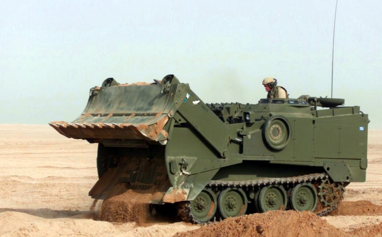
This M9 is engaged in scraping operations. The dozer blade is in the raised position, allowing dirt into the scraper bowl. This vehicle is being used by a marine to create berms during Operation Enduring Freedom. (Picture taken 6 Feb 2003 by LCPL Kevin C. Quihuis, Jr.; available from the Defense Visual Information Center.)
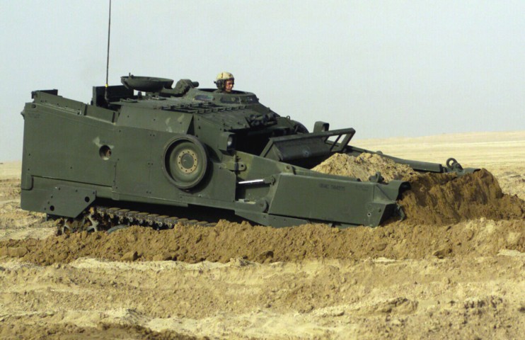
The scraper bowl on this machine is filled with dirt, which could increase its weight by 20,000lbs (9,000kg). The vehicle's operator is PFC Shawn Janecek from C Company, 1st Combat Engineer Battalion, 1st Marine Division, and he is creating tank crossing points during Operation Enduring Freedom. (Picture taken 8 Feb 2003 by Sgt. Paul L. Anstine II; available from the Defense Visual Information Center.)
