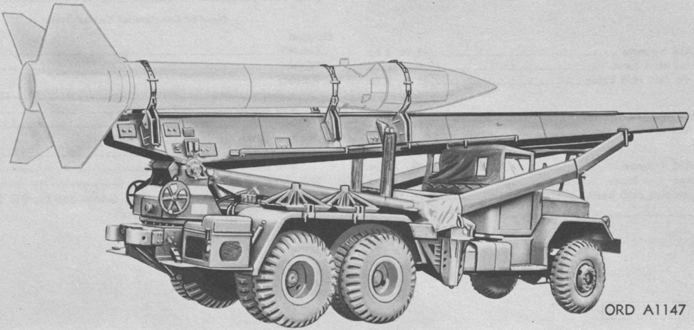
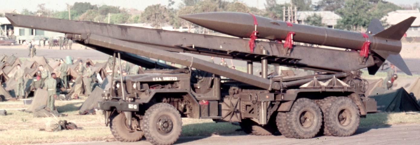
762mm Truck-mounted Rocket Launcher M289.
The M289 used an extended-wheelbase 6x6 5-ton truck chassis with modifications to deal with the weight carried and to increase tractive performance. Five screw jacks were used to level the launcher for firing, and rocket-launching equipment included the launching beam assembly, elevating mechanism group, the electrical system, equilibrator assemblies, and the traversing mechanism group. A gasoline-engine generator set M25 was also carried. (Picture from TM 9-500 C3 Data Sheets for Ordnance Type Materiel.)
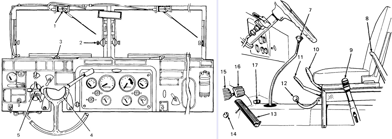
Cab controls are detailed in these sketches. 1. Windshield wiper lever. 2. Windshield clamping screws. 3. Windshield locking handle. 4. Horn button. 5. Directional turn signal control. 7. Transmission gearshift lever. 8. Transmission and power divider power takeoff control lever. 9. Handbrake control lever. 10. Front winch control lever. 11. Transfer shift lever. 12. Transfer power takeoff control lever. 13. Accelerator pedal. 14. Dimmer switch. 15. Clutch pedal. 16. Service brake pedal. 17. Bracket for mounting decontamination apparatus. (Picture from TM 9-2320-211-10 C2.)
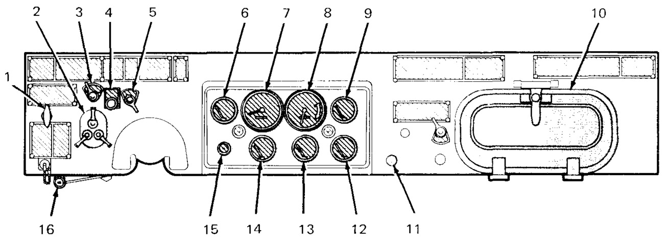
The driver's instrument panel is labeled. 1. Hand throttle control throttle knob. 2. Light switch. 3. Ignition switch. 4. Anti-diesel control. 5. Fuel tank selector switch [not used on M139 series]. 6. Fuel gage. 7. Speedometer/odometer. 8. Tachometer. 9. Engine coolant temperature gage. 10. Glove compartment. 11. Choke control. 12. Battery-generator indicator. 13. Air pressure gage. 14. Oil pressure gage. 15. Headlight high beam indicator. 16. Windshield wiper control. (Picture from TM 9-2320-211-10 C2.)
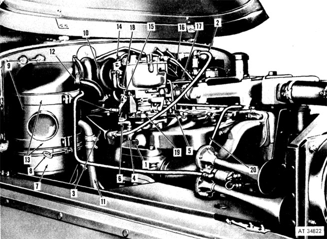
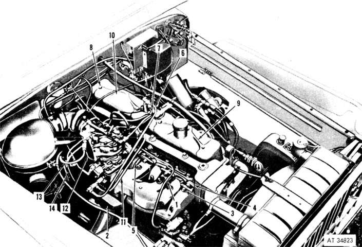
The Continental R6602 is shown here installed in the truck. Unlabeled air horns are at the lower right of the image. Its compression ratio was 6.4:1. 1. Pipe plug. 2. Vacuum line. 3. Distributor vent line. 4. Crankcase ventilating shutoff valve. 5. Cylinder head priming tee. 6. Shutoff valve lever. 7. Oil cup. 8. Thumb screw. 9. Air cleaner body. 10. Air cleaner-to-carburetor inlet hose. 11. Air cleaner-to-air compressor intake line. 12. Air cleaner outlet hose. 13. Mounting bands. 14. Hose clamp. 15. Throttle valve plate lever. 16. Fuel pump-to-carburetor line. 17. Governor valve-to-governor line. 18. Carburetor-to-governor valve line. 19. Safety nut. 20. Intake manifold. (Picture from TM 9-2320-211-20 C3.)
The engine is illustrated from the top right. 1. Air compressor-to-governor line. 2. Exhaust pipe mounting flange. 3. Hexagon nut. 4. Manifold clamp. 5. Heat shield. 6. Vacuum line. 7. Crankcase ventilating line connector. 8. Cap screw. 9. Front rocker arm cover. 10. Rear rocker arm cover. 11. Distributor vent line. 12. Carburetor-to-governor valve line. 13. Carburetor-to-governor valve line. 14. Governor valve control valve-to-governor line. (Picture from TM 9-2320-211-20 C3.)
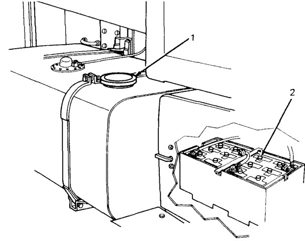
The M139 truck had a single fuel tank under the passenger door, and two 12-volt lead-acid batteries were connected in series for the 24-volt electrical system. (Picture from TM 9-2320-211-10 C2.)
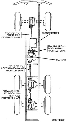
The axle driving and propeller shafts are diagrammed in this sketch. (Picture from TM 9-2320-211-20 C3.)
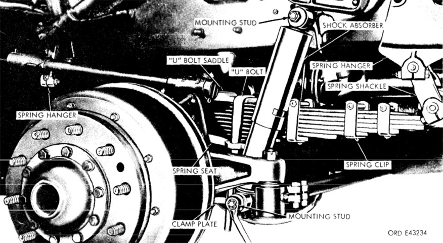
The left front suspension spring and shock absorber are labeled. M139 series trucks used twelve 3" (7.6cm) Standard Steel Spring Co. leaves in their front leaf springs, an increase over the regular truck's ten leaves. The shock absorbers were Deko Products Div. Model 750-T nonadjustable, double-acting units. (Picture from TM 9-2320-211-20 C3.)
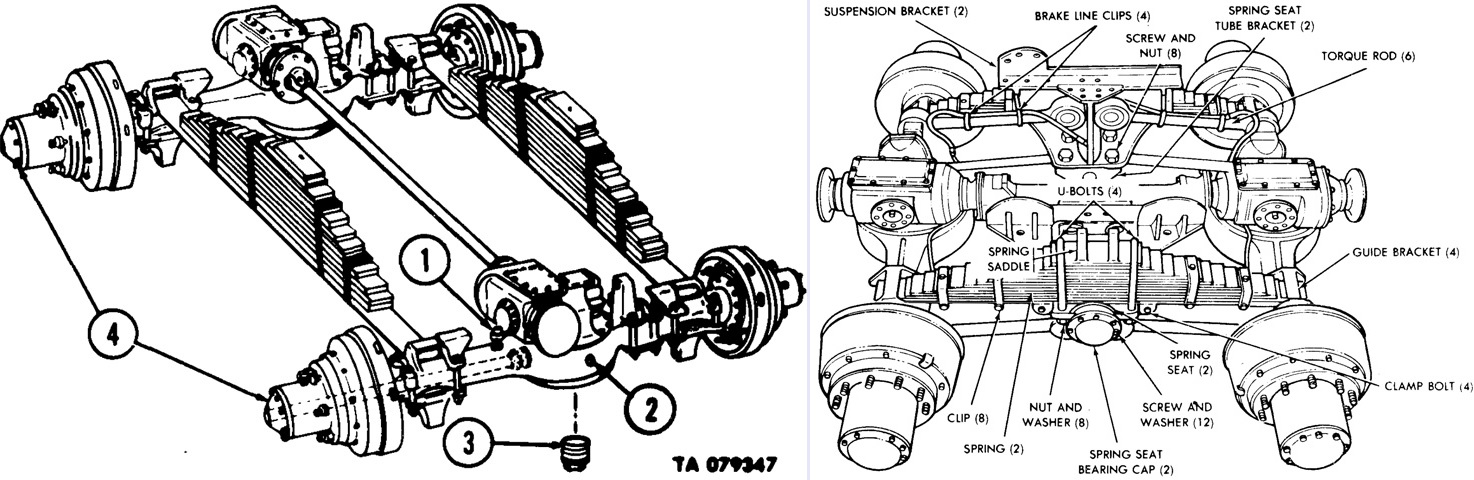
The rear suspension system is drawn above. The two hypoid, double-reduction, single speed rear axles were identical and mounted in tandem. Two torque rods on the right side of the axle and a single torque rod on the left connected the axles to the rear suspension brackets. The rear springs were Standard Steel Spring Co. model SSS-9113 units with thirteen 4"x59¼" (33cm x 150.5cm) leaves. The legend for the left image is: 1. Breather valves. 2. Differential fill plug. 3. Differential drain plug. 4. Axle drive flange bolts. (Picture from TM 9-2320-211-20 C3.)
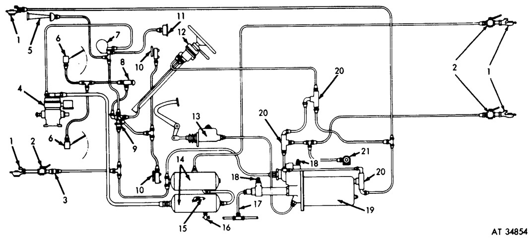
The compressed air system is diagrammed. The reservoirs were 7" (18cm) in diameter, and the lower reservoir featured a safety valve that opened at 150psi (10.5kg/cm²) as well as a drain cock for eliminating condensation from the reservoirs. 1. Trailer coupling. 2. Trailer coupling cutout cocks. 3. Single check valve. 4. Air compressor. 5. Horn. 6. Windshield wiper. 7. Air governor. 8. Windshield wiper control valve. 9. Junction block. 10. Air supply valve. 11. Air pressure gage sending unit. 12. Hand-control valve. 13. Master cylinder. 14. Air reservoir. 15. Air reservoir safety valve. 16. Air reservoir drain cock. 17. Hydraulic line to wheel. 18. Hydraulic bleeder valve. 19. Air hydraulic brake cylinder. 20. Double check valve. 21. Stoplight switch. (Picture from TM 9-2320-211-20 C3.)
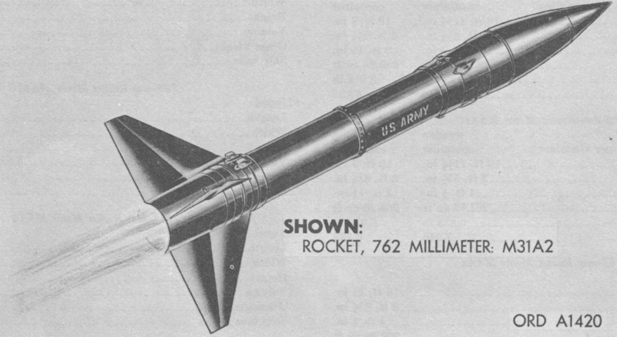
A 762mm rocket M31A2 is drawn above. The M31 series were transported in three containers: one for the rocket motor, one for the fins, and one for the warhead assembly. The rocket motor was the portion that contained the propellant, spin rockets, and the ignition system, while the warhead was at the front of the rocket. The M31A1, M31A1C, and M31A2 could all use 762mm rocket fins M136A1, M136A2, or M136A2B1. The complete round diameter was 30" (76.2cm), fin span was 104" (264cm), length was 327" (831cm), and gross weight was 5,913lb (2,682kg). The rocket motors M3A1, M3A1C, and M3A2 were 27.7" (70.4cm) in maximum diameter, 212" (538cm) long, and weighed 4,109lb (1,864kg), with 2,063lb (935.8kg) of that being explosive. (Picture from TM 9-500 C3 Data Sheets for Ordnance Type Materiel.)
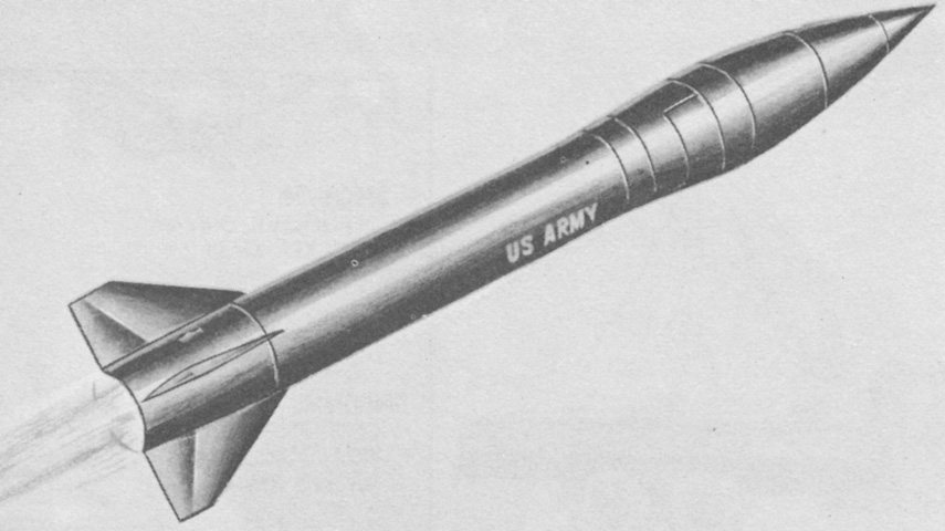
The fins M17 on the 762mm rocket M50 had a span of only 55¾" (141.6cm), and its lighter rocket motor M66 contributed to a lower gross weight of 4,719.1lb (2,140.6kg). The rocket was 298½" (758.2cm) long, and the M66 motor's firing temperature limits were -30 to 100°F (-34 to 38°C). (Picture from TM 9-500 C3 Data Sheets for Ordnance Type Materiel.)
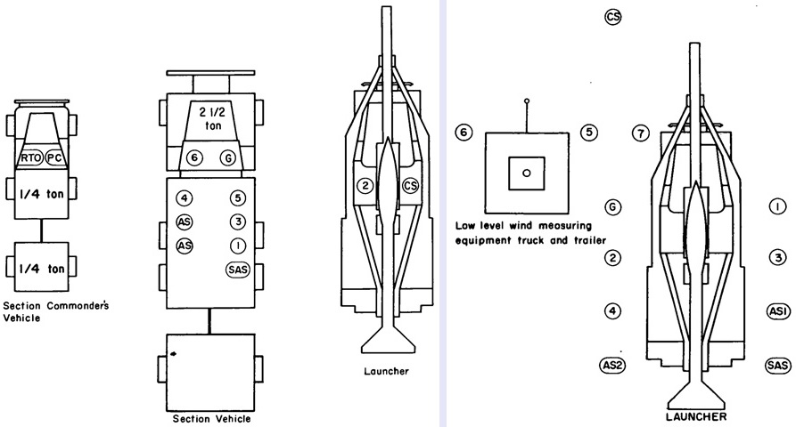
The mounted posts of the firing section are illustrated on the left, with the M289 on the right of the image. The firing section was composed of the launcher; a low-level wind measuring set; and ancillary equipment; and was manned by a platoon (section) commander; chief of section; gunner; senior assembly specialist; two assembly specialists; a radio telephone operator who doubled as the light truck driver; and six launcher crewmen numbered 1-6, with number 2 driving the launcher and number 6 driving the section truck. The personnel posts when prepared for action are sketched on the right. (Picture from FM 6-60 C2 Field Artillery Rocket Honest John with Launcher M289.)
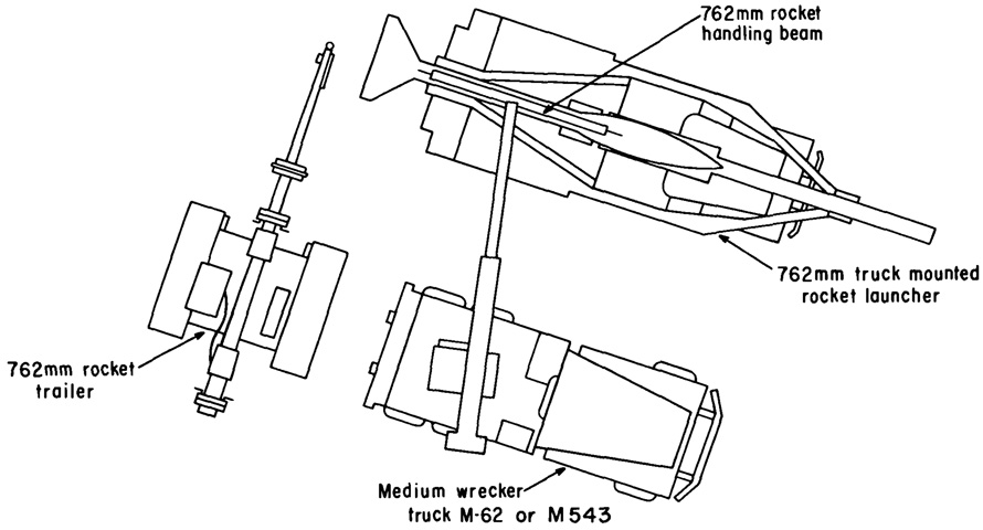
The rocket is being loaded in this drawing. The position of the vehicles would depend on the terrain, but ideally the extension distance for the wrecker boom would be minimized since the assembled rocket overloaded a fully-extended boom. Loading normally took place at some distance from the firing position, but could occur at the firing position if necessary. Heating blankets were available if the ambient temperature required warming the rocket motor. (Picture from FM 6-60 C2 Field Artillery Rocket Honest John with Launcher M289.)
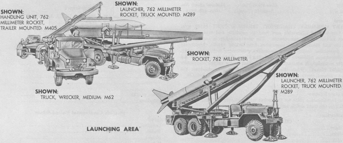
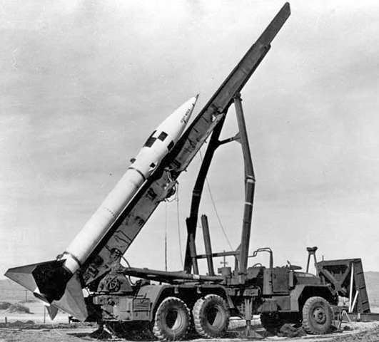
An M31-series rocket is shown being loaded onto the launching rail on the upper left, and the M289 is ready to fire on the bottom right. Note the screw jacks that have been lowered to provide stability and to level the launcher. The launcher beam was considered unserviceable if it curved upward at all, downward by more than 27/32" (2.1431cm), or 7/16" (1.111cm) to either side. (Picture from TM 9-500 C3 Data Sheets for Ordnance Type Materiel.)
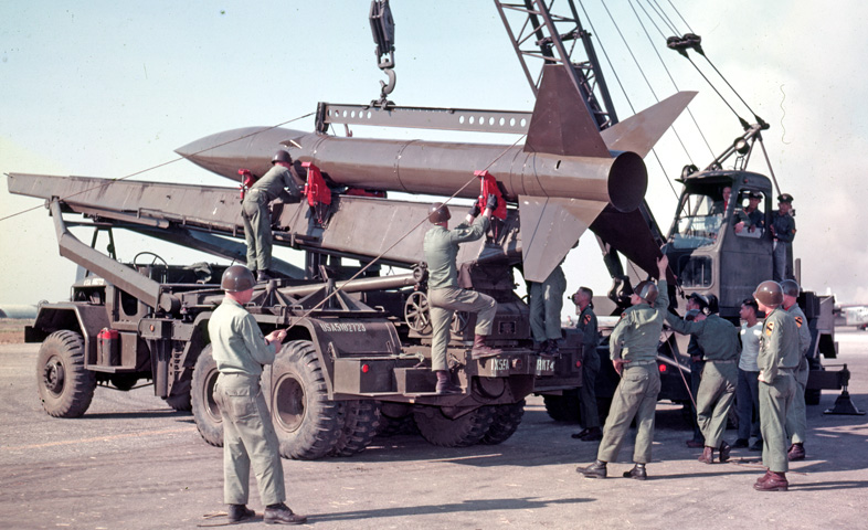
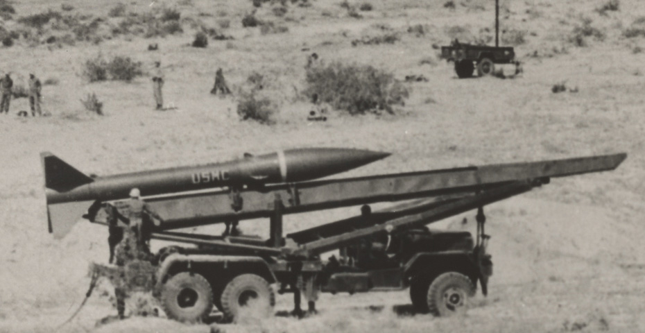
A firing section from the 5th Rocket Battery is seen loading an assembled M31 series rocket onto the launching rail during Operation Firm Link. (Picture taken 15 Feb 1956; available from the National Archives.)
The loading process has been accomplished. Note the stowed outrigger jack support behind the cab, with two more secured to the top of the rear fender. (Picture taken 15 Feb 1956; available from the National Archives.)
The vehicle's fuel tank can be seen on the right-side running board. Note the lowered screw jacks. The wind-measuring set trailer is deployed in the background. (Picture available from the National Archives.)
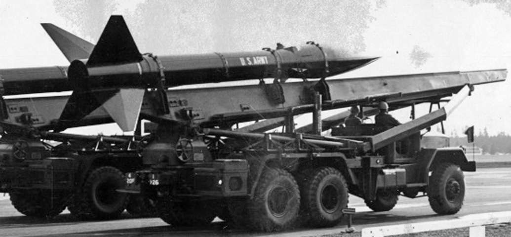
Both crewmembers are in position during this parade. With the launch rail essentially bifurcating the cab, their helmets seem like necessary precautions. (Picture available from Redstone Arsenal Historical Information.)
The launch rail is at a high elevation. (Picture available from Redstone Arsenal Historical Information.)
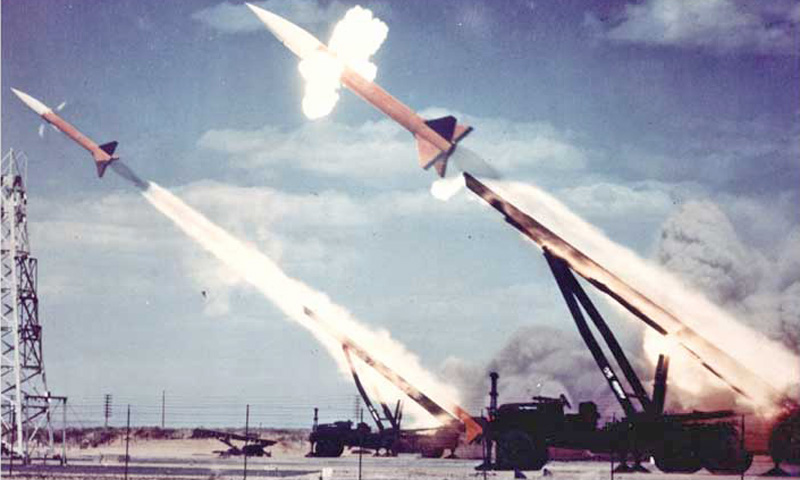
The simultaneous launch of a pair of rockets is an impressive spectacle. Exhaust from the spin motors near the warhead section is visible. (Picture available from Redstone Arsenal Historical Information.)
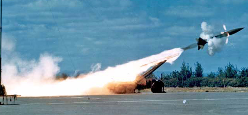
Another launch at a shallower angle again shows the activation of the spin motors. (Picture available from Redstone Arsenal Historical Information.)
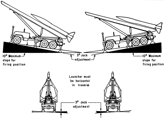
Maximum allowable forward and rearward slope for firing was 10°, while no cant was permissible. The outrigger jacks provided 3° of adjustment front/rear and to each side. Full traverse was only possible if the launcher-beam separation angle was greater than 213 mils; therefore, if maximum range was needed, traverse would be limited unless the launcher was positioned on a forward slope. (Picture from FM 6-60 C2 Field Artillery Rocket Honest John with Launcher M289.)
