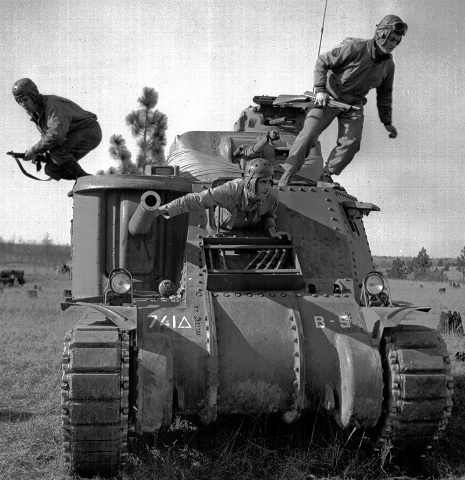
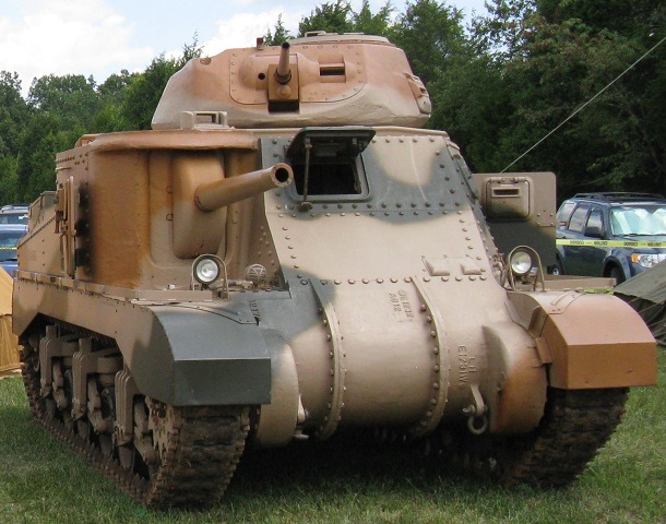
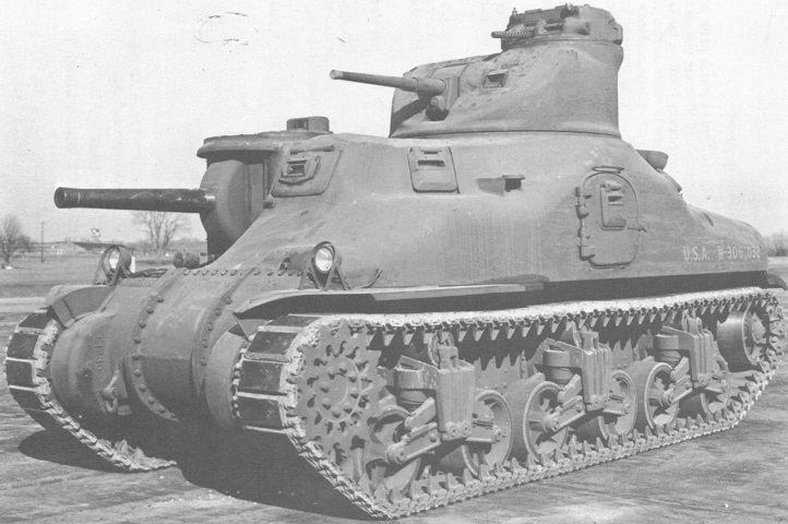
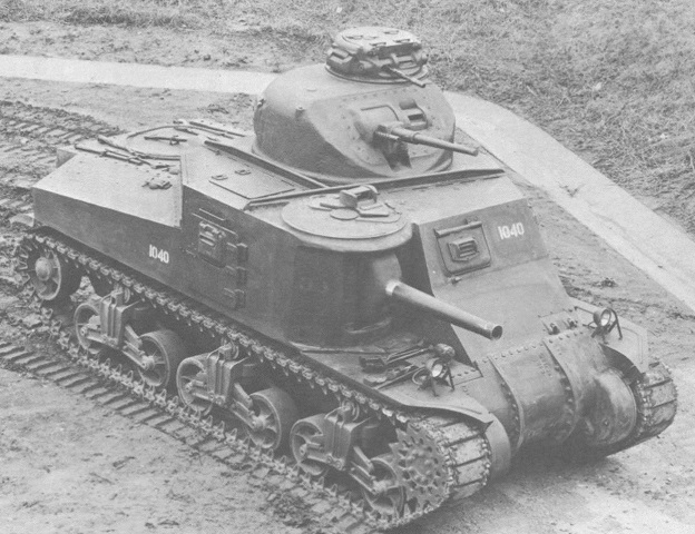
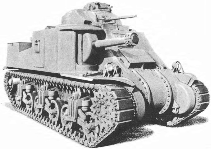
Medium Tank M3 Lee in Camp Polk, Louisiana.
The riveted construction of the medium tank M3 is obvious here. The machine gun in the commander's cupola is present in its right aperture, and one of the driver's hull machine guns has been retained. Track grousers are stored in the box below the driver's hatch, and the tank's siren is positioned below the 75mm gun. Here the crew, Cpl. Larry Corletti, Pvt. Murril Chapman, and Pvt. Louis Robles, practice dismounting from a disabled vehicle. (Picture taken 12 Feb 1943 by Sgt. Calvano; available from the U.S. Army Center of Military History.)
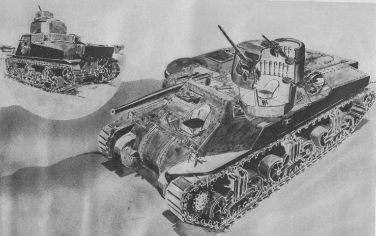
This stylized sketch shows a ghosted glimpse of the interior. The driver's seat is centered in the hull front, and the 37mm gunner was seated in the turret. The commander was provided with positions in the turret rear and the cupola. (Picture from TM 9-750 Medium Tanks M3, M3A1, and M3A2.)
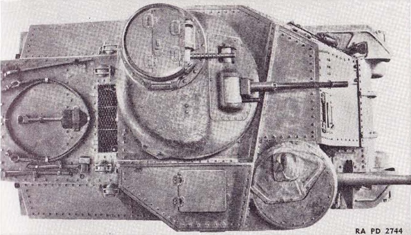
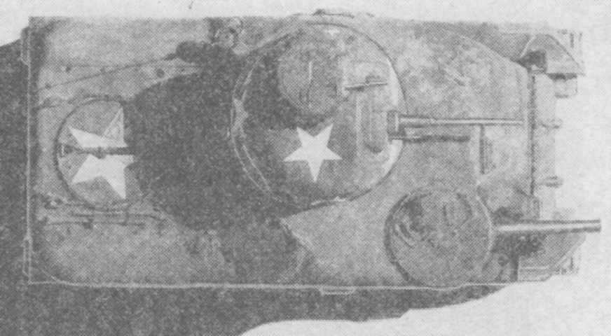
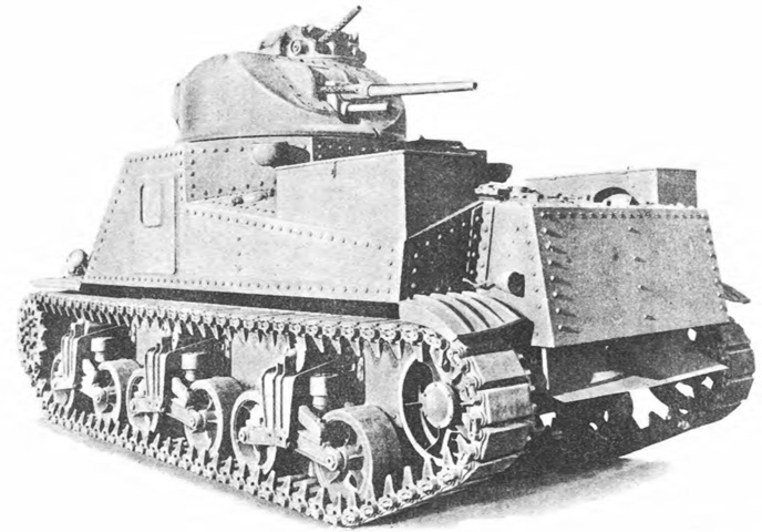
The asymmetric design of the tank is highlighted in this top view. A towing cable and tools are stowed on the rear deck, and the filler covers for the four fuel tanks can be seen on each side of the engine air intake grille. (Picture from TM 9-750 Medium Tanks M3, M3A1, and M3A2.)
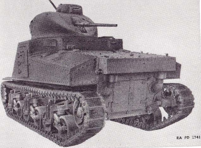
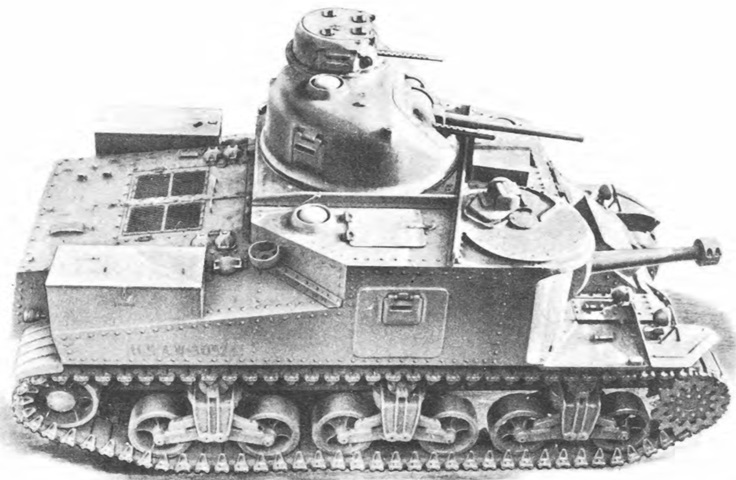
This early-production tank is fitted with pepperpot-style exhaust mufflers in contrast to the vehicles below. (Picture from TM 9-750 Medium Tanks M3, M3A1, and M3A2.)
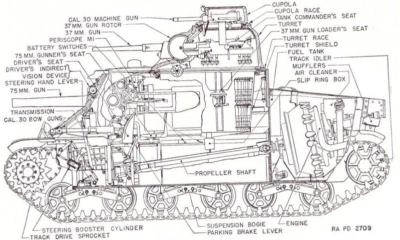
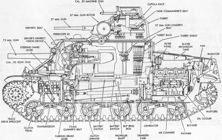
A cross-sectional view of the tank is provided in this image. This tank also has the early exhaust and air cleaner setup. (Picture from TM 9-750 Medium Tanks M3, M3A1, and M3A2.)
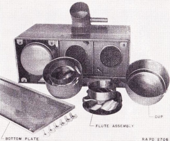
An early air cleaner assembly is shown here. One could be found at each rear corner of the engine compartment, and they were of the oil bath type. (Picture from TM 9-750 Medium Tanks M3, M3A1, and M3A2.)
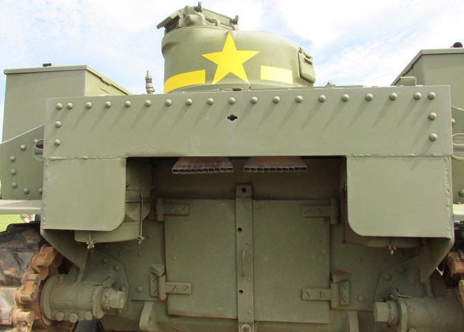
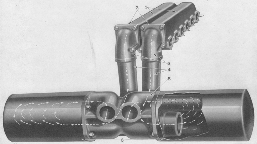
This tank has the later air cleaner and exhaust system. The rectangular exhaust pipes are now in the center, with the engine's air cleaners in each upper corner. Engine access was provided by the double doors, and the hole in the rear armor was for the engine hand crank. The external air cleaners were vulnerable to damage from enemy fire, so extra protection was added around them later in production.
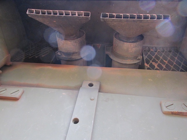
A close-up of the twin exhaust tips is shown here.
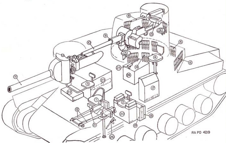
1. Driver's seat. 2. Radio operator's seat. 3. 75-mm gunner's seat. 4. 37-mm gunner's seat. 5. 37-mm loader's seat. 6. Tank commander's seat. 8. Cal. .30 machine gun. 9. Cal. .30 machine gun. 10. 37-mm gun. 11. 75-mm gun. 12. 2 cal. .30 machine guns. 13. Protectoscopes. 14. 51 rounds 37-mm ammunition carried in turret. 15. 13 rounds 37-mm ammunition. 16. 11 rounds 37-mm ammunition. 17. 42 rounds 37-mm ammunition. 18. Ten 100-round belts cal. .30 ammunition. 19. 20 rounds 37-mm ammunition. 20. Fourteen 250-round belts containing 225 rounds cal. .30 ammunition. 21. Two 250-round belts containing 225 rounds cal. .30 ammunition. 22. Twenty-five 100-round belts cal. .30 ammunition [sic]. 23. 41 rounds 75-mm ammunition; six 100-round belts cal. .30 ammunition. 24. 42 rounds 37-mm ammunition. 25. Submachine gun. 26. Submachine gun. Carried in tank but not shown on drawing are 9 rounds 75 mm ammunition carried in cartons and twenty-four 50-round clips cal. .45 ammunition. [In addition, two 250-round belts containing 225 rounds of .30cal ammunition were carried on the turret platform, one belt in the combination gun mount, three belts beside the propeller shaft housing, four belts forward above the propeller shaft, and six belts on the tool box. Six 100-round belts of .30cal ammunition were stowed in a box over the propeller shaft next to the 75mm supply, and four were above the propeller shaft housing. A total of twenty 100-round belts and thirty-two 250-round belts loaded with 225 rounds each were carried.] (Picture from TM 9-750 Medium Tanks M3, M3A1, and M3A2.)
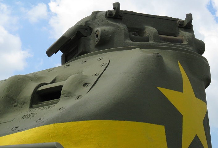
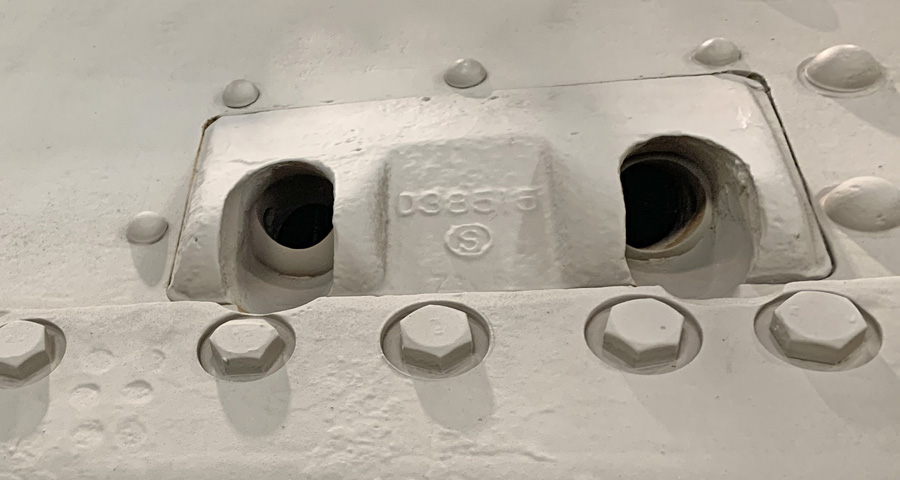
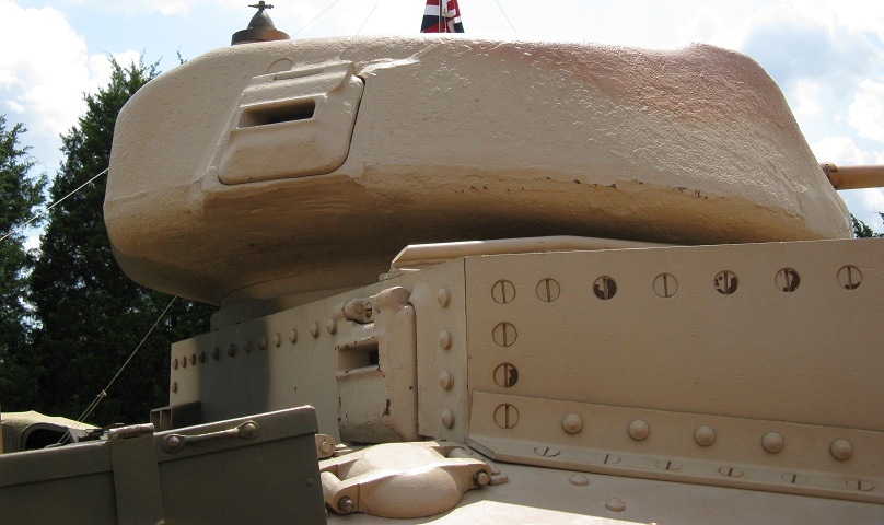
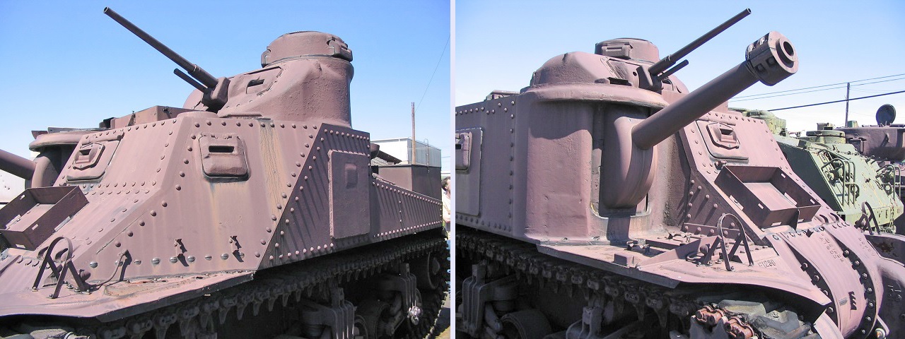
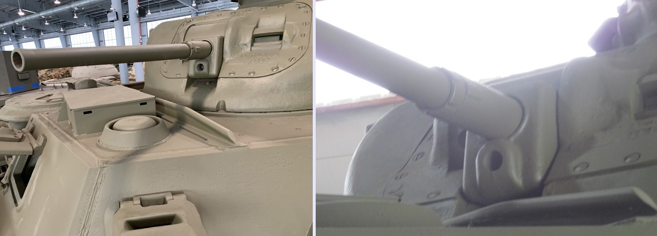
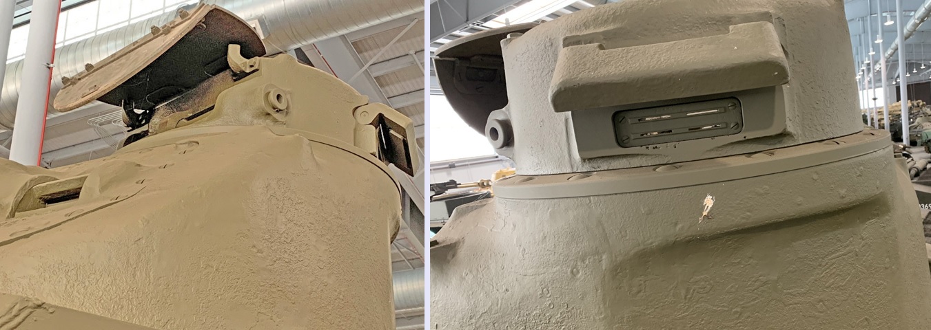
The US version of the M3 kept the radio in the hull and featured a large machine gun cupola for the tank commander. The front of the TC's cupola is shown on the left. The aperture for the .30cal machine gun is on the commander's right side, and a protectoscope was housed in the opposite opening. The machine gun did have limited traverse independent of the cupola. Below, the opening for the 37mm gunner's periscope M2 can be seen on the turret front. The right image shows the rear of the turret with its short overhang, and the cupola is rotated to almost 9 o'clock. A vision slot is open on the side of the cupola, and a ventilator is visible beside the cupola.
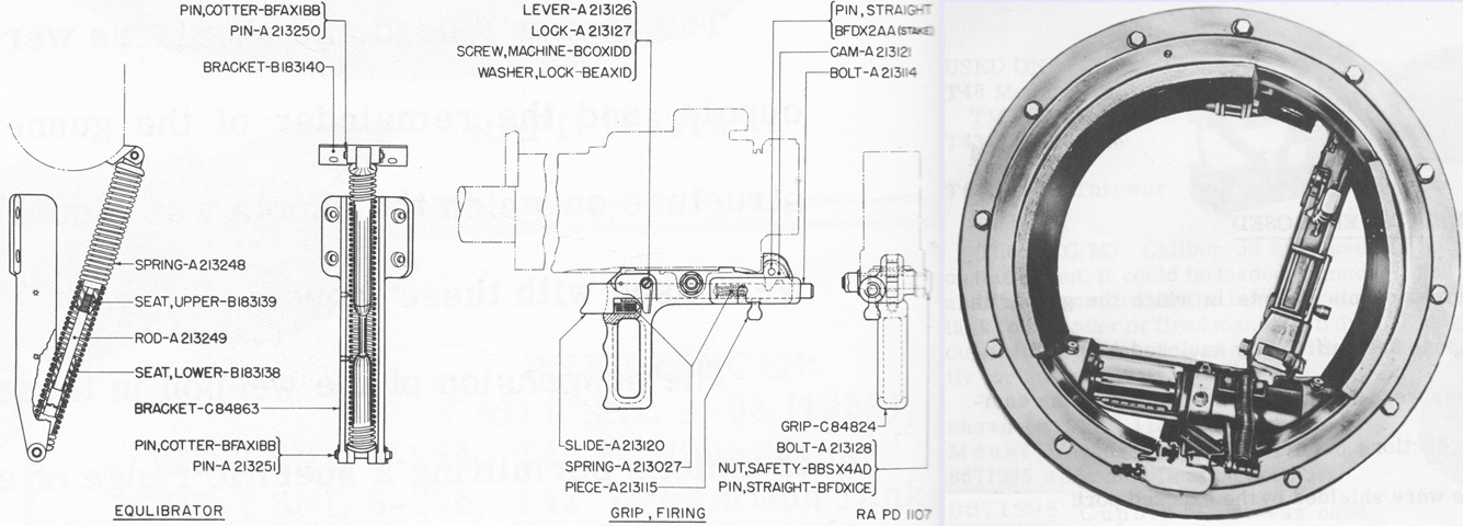
The commander's machine gun mount was equilibrated with a spring connecting the machine gun rotor to the cupola's concentric ring. To enable the commander to aim and fire the gun, a firing grip was installed to the underside of the weapon. The equilibrator spring is seen on the left above, and the grip assembly is in the center. On the right, a view of the machine gun is provided from below with the spring and grip visible. The machine gun is secured in its gun latch at the cupola rear, but it is evident how little room remains behind the machine gun. (Picture from Weapon Mounts for Secondary Armament.)
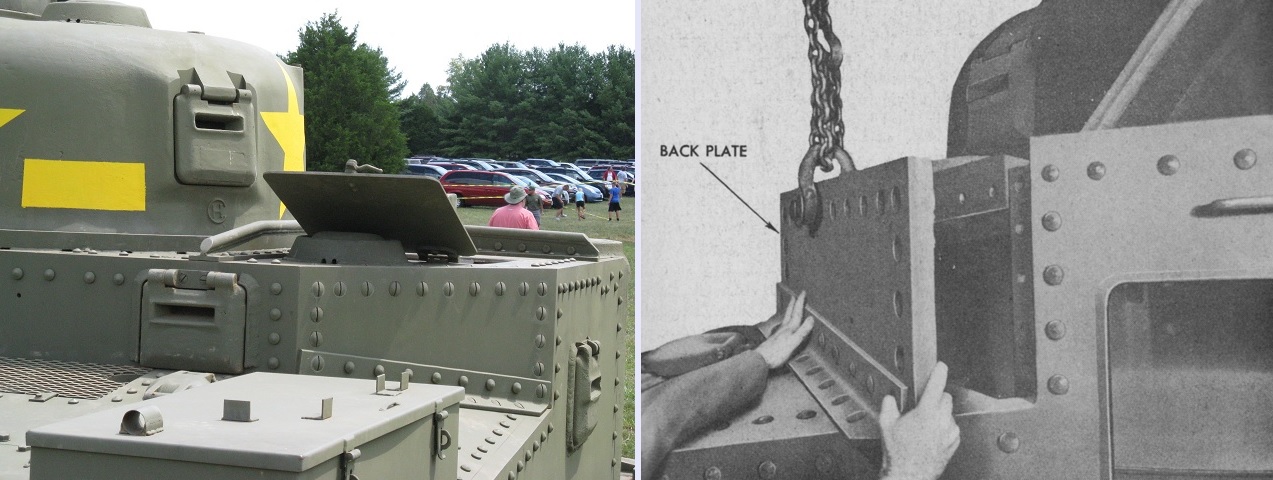
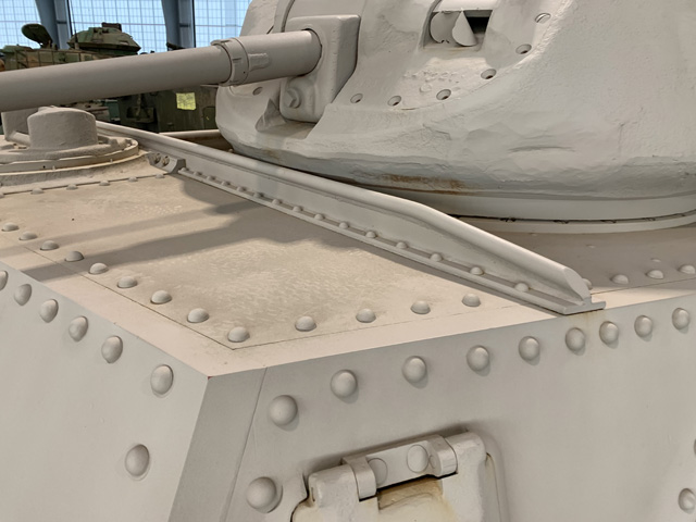
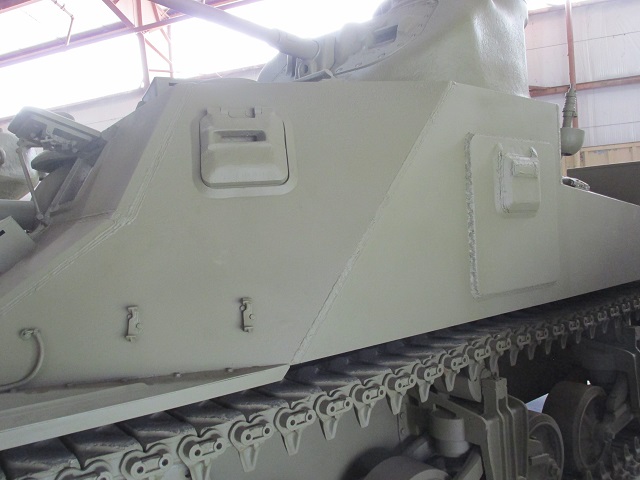
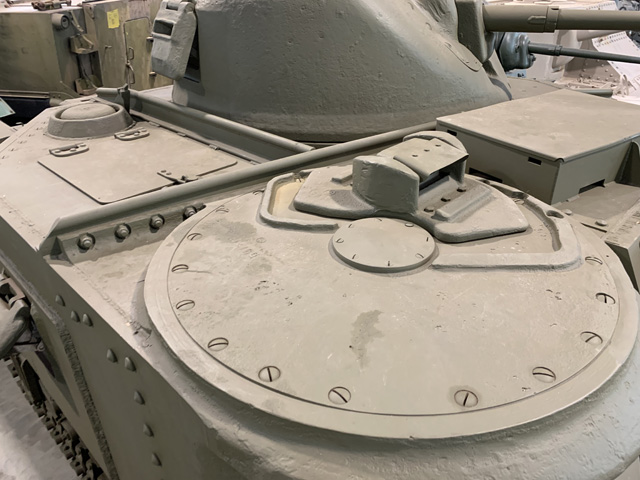
The tank on the left is a later-production vehicle, as indicated by the ventilators and the lack of side hull doors. The pistol ports and roof hatch over the 75mm gun sponson were retained, however. A stowage box is mounted on the rear deck, and the pistol ports feature protectoscopes. Note that the armor panel to the lower right of the ventilator was secured by slotted screws rather than rivets; as seen on the right, this panel could be dismounted to ease installation or removal of the 75mm gun. (Right picture from TM 9-1307 Ordnance Maintenance--75-mm Tank Guns M2 and M3 and Mounts M1, M34, and M34A1.)

The 75mm gun could be wrestled out of the rear opening after it was turned on its side. If necessary, the gun cradle assembly could be taken out through the hull top hatch. (Picture from TM 9-1307 Ordnance Maintenance--75-mm Tank Guns M2 and M3 and Mounts M1, M34, and M34A1.)
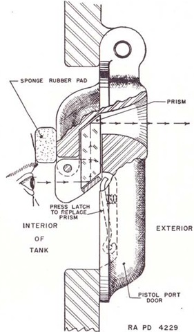
A cross-section of a protectoscope is drawn here. The user was shielded against incoming fire via the prism that displaced the operator's eyes downward behind armor. (Picture from TM 9-750 Medium Tanks M3, M3A1, and M3A2.)
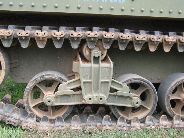
The suspension on the M3 was based on that of the medium tank M2. This vehicle is not fitted with the later, heavy-duty volute springs that necessitated moving the track return roller to the rear of the assembly.
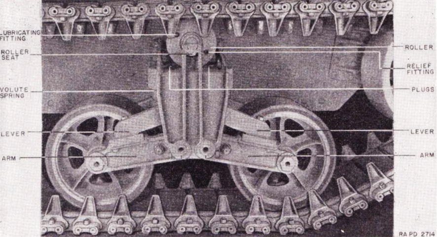
The components of a suspension bogie are labeled here. (Picture from TM 9-750 Medium Tanks M3, M3A1, and M3A2.)
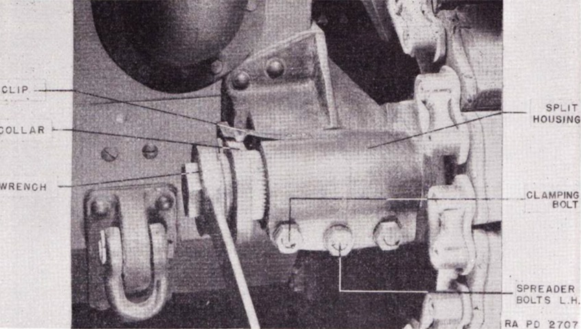
Track tension was adjusted by first loosening the two outside clamping bolts that secured the split housing, and the split housing was then opened by turning the spreader bolt. With the split housing loosened, the clip at the end of the spindle was raised, and the collar was driven off of the serrations on the spindle. The idler could then be adjusted by turning the spindle shaft with the appropriate wrench. (Picture from TM 9-750 Medium Tanks M3, M3A1, and M3A2.)
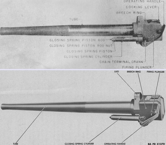
The 75mm gun M2 is above, with the 75mm gun M3 below. The major difference between the models was the gun tube length, which was 27.3" (69.3cm) longer in the M3. The complete M2 weighed 783lb (355kg), and the rifling was a uniform right hand twist with one turn in 25.59 calibers. The M3 was 893lb (405kg) with the same rifling. (Picture from FM 23-95 75-mm Tank Gun M2 (Mounted in Medium Tank M3) and TM 9-1307 Ordnance Maintenance--75-mm Tank Guns M2 and M3 and Mounts M1, M34, and M34A1.)
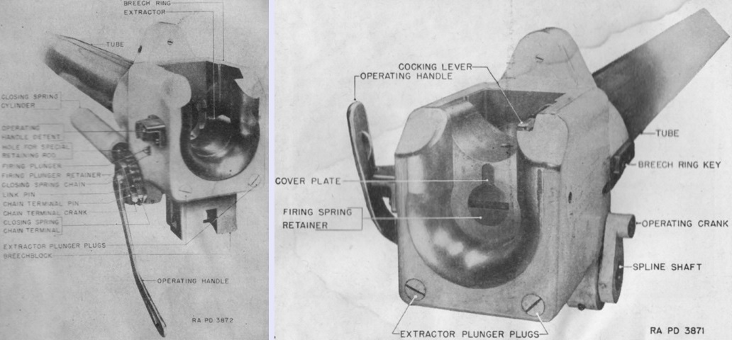
The automatically-operated vertical sliding breechblock is seen in the full open position on the left and closed on the right. (Picture from FM 23-95 75-mm Tank Gun M2 (Mounted in Medium Tank M3).)
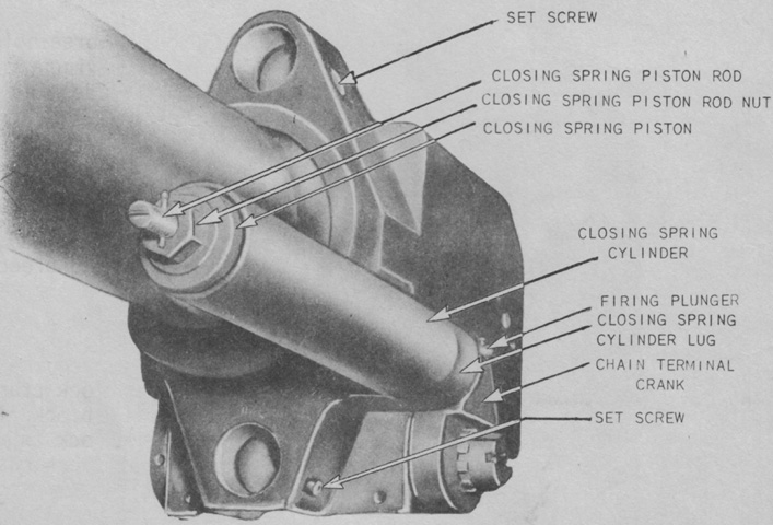
When a round was inserted into the chamber, the rim would strike the lips of the extractors, rotating the upper portions of the extractors forward. This movement disengaged the extractors' inner trunnions from the breechblock's trunnion seats, which allowed the breechblock to rise into the closed position due to the action of the closing spring, seen here. (Picture from Conference on the 75mm M-2 Tank Gun.)
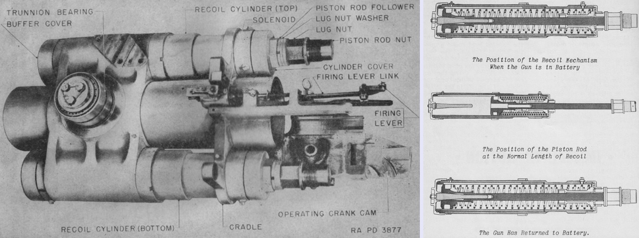
The left side of the recoil mechanism is detailed in the left image. The gun would recoil ~11.5" (~29.2cm) when fired. Piston rods in the top and bottom recoil cylinders were attached to the breech ring, and were consequently pulled to the rear along with the gun. These pistons were pulled through the hydraulic oil in the cylinders, and the action of the oil flowing through half-round tapered grooves in the bronze cylinder sleeves along with the compression of four counterrecoil springs during the rearward movement arrested the motion of the gun. The counterrecoil springs then expanded to return the ordnance to battery. Forward movement was controlled by oil flowing around the pistons through the cylinder grooves, and near the end of the counterrecoil stroke the tapered buffer at the front of the cylinder would enter the hole in the front of the piston rod, forcing oil out of the hole as the piston moved forward.
On the right, the action of the recoil cylinder is drawn with the gun in battery at the top, at maximum recoil in the center, and upon return to battery at the bottom. The buffer is visible at the front of the cylinder, and its entrance into the piston rod can be observed. (Picture from FM 23-95 75-mm Tank Gun M2 (Mounted in Medium Tank M3).)
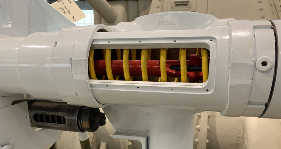
This 75mm gun mount has been cut open to be used as training device. Looking at the mount from the bottom, the recoil spring has been painted yellow, and the piston and rod are red. The buffer is also visible inside the cut away portion of the piston rod. The smaller closing spring can be seen under the recoil cylinder. When the gun mount was installed, the closing spring was to the left of the gun. The close-up on the right reveals a tapered groove in the cylinder wall that allowed oil to flow around the moving piston.
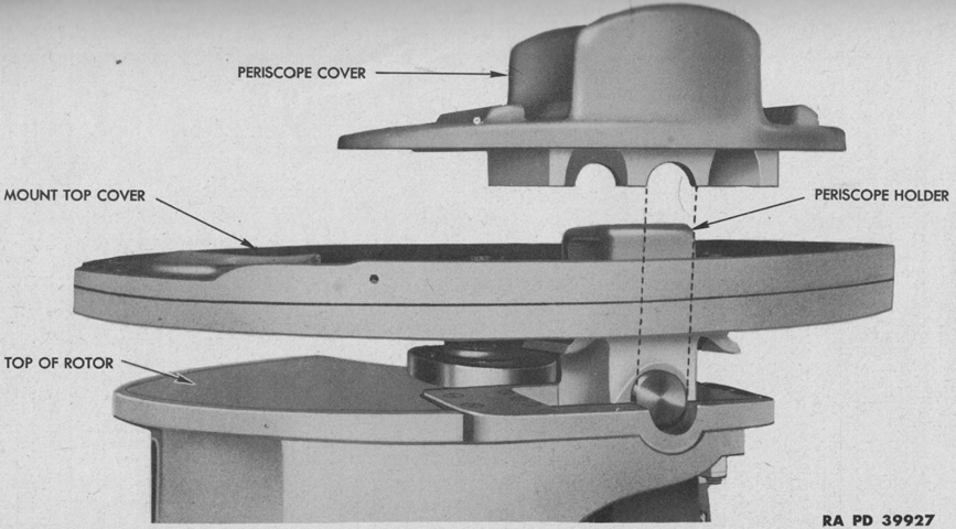
The top of the 75mm gun mount is viewed from the inboard side; the gun would be facing to the left. The top cover was secured to the hull by twenty bolts. (Picture from TM 9-1307 Ordnance Maintenance--75-mm Tank Guns M2 and M3 and Mounts M1, M34, and M34A1.)
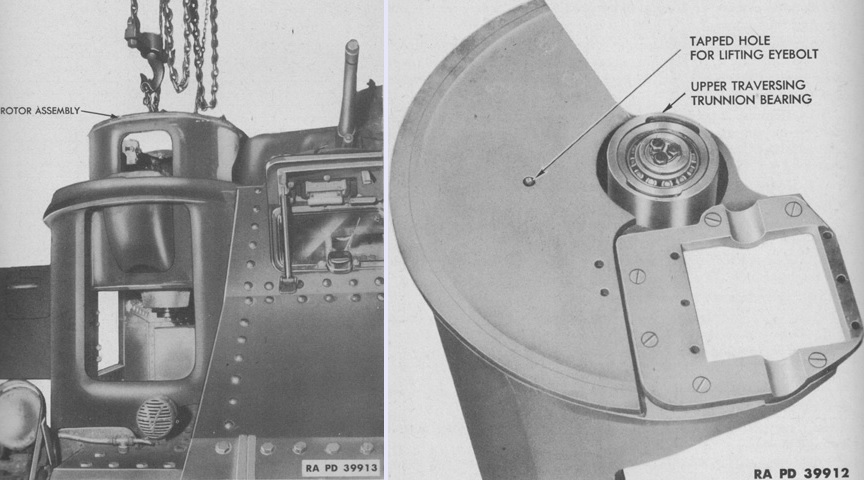
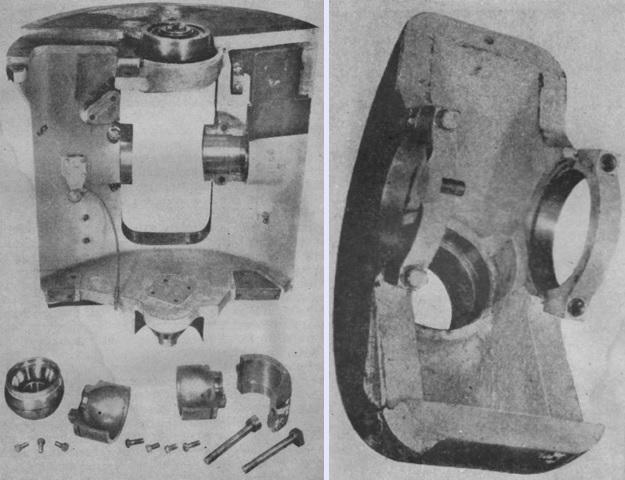
The rotor assembly is being removed from the hull in this image; as seen on the right, a tapped hole in the top of the rotor assembly accepted a ¾" (1.9cm) eyebolt for this purpose. The 37mm gun turret remained in place. (Picture from TM 9-1307 Ordnance Maintenance--75-mm Tank Guns M2 and M3 and Mounts M1, M34, and M34A1.)
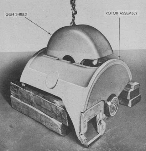
The 75mm gun shield is being lifted from the rotor assembly. (Picture from TM 9-1307 Ordnance Maintenance--75-mm Tank Guns M2 and M3 and Mounts M1, M34, and M34A1.)
The 75mm gun's horizontal rotor is seen from the rear in the left picture. The gun, elevating shield, and recoil mechanism were all supported by the trunnion in the trunnion seats of the rotor, and the entire assembly was supported by a vertical thrust roller bearing on the bottom of the rotor. The horizontal rotor weighed 875lb (397kg). The interior of the 75mm gun's elevating shield is shown on the right. The elevating shield weighed 442lb (200kg), and extended through the horizontal rotor via the large rectangular cutout in the latter. The elevating shield retained and protected the recoil mechanism, to which it was connected via the recoil mechanism trunnions. The gun tube passed through the circular opening to the front. (Picture from FM 23-95 75-mm Tank Gun M2 (Mounted in Medium Tank M3).)
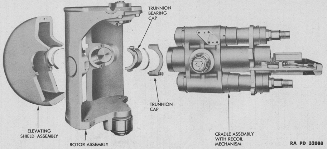
The gun mount M1's gun shield, rotor, and cradle assembly with the recoil mechanism are exploded in this image. (Picture from TM 9-1307 Ordnance Maintenance--75-mm Tank Guns M2 and M3 and Mounts M1, M34, and M34A1.)
The short 75mm gun M2 is shown here with the parts of the gun mount labeled. One turn of the traversing handwheel moved the gun by 1°6', and a revolution of the elevation handwheel produced 1°8' of elevation or depression. (Picture from FM 23-95 75-mm Tank Gun M2 (Mounted in Medium Tank M3) and TM 9-1307 Ordnance Maintenance--75-mm Tank Guns M2 and M3 and Mounts M1, M34, and M34A1.)
The 75mm gun mount is seen from the left side. The gunner's seat was fixed and did not follow the gun mount as it was aimed. (Picture from TM 9-750 Medium Tanks M3, M3A1, and M3A2.)
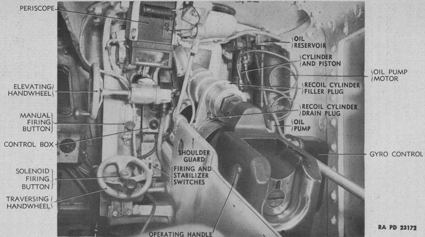
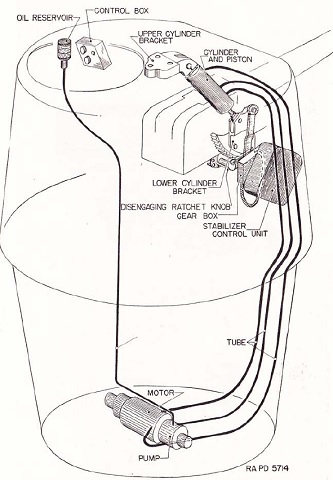
This tank is equipped with an elevation stabilizer, and its installation around the 75mm gun is detailed. (Picture from TM 9-1307 Ordnance Maintenance--75-mm Tank Guns M2 and M3 and Mounts M1, M34, and M34A1.)
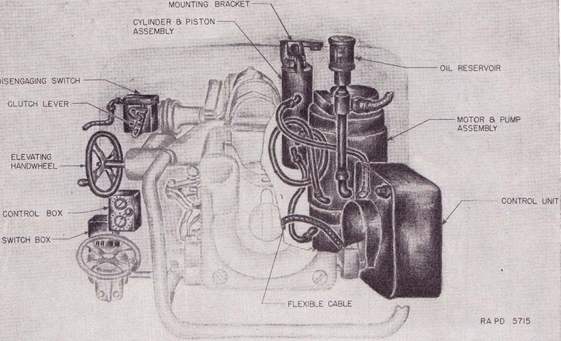
The various components of the 75mm gun stabilizer are outlined here. (Picture from TM 9-750 Medium Tanks M3, M3A1, and M3A2.)
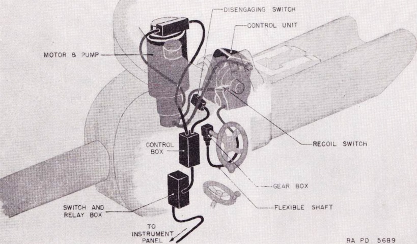
The 75mm stabilization system is diagrammed from another angle. (Picture from TM 9-750 Medium Tanks M3, M3A1, and M3A2.)
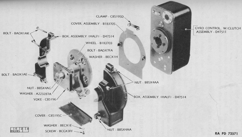
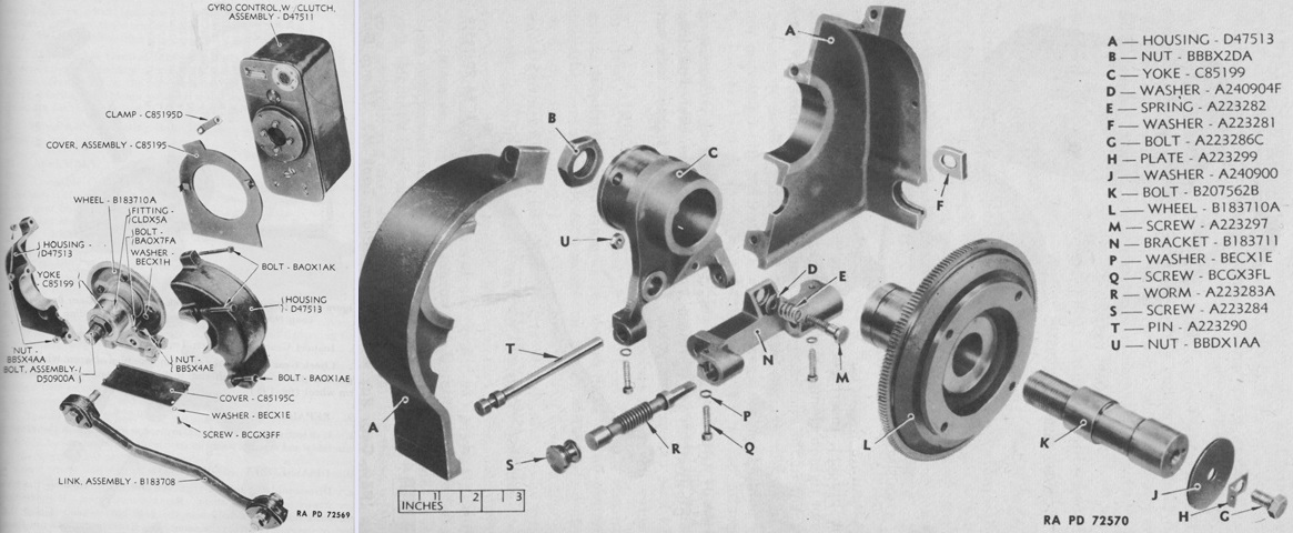
An exploded view of the gyro control gearbox for the 75mm gun is shown in this image. The gearbox regulated the angular relationship between the gyro control and the gun. The gearbox was attached to the gun mount, and the gyro control was fastened to the gearbox's worm wheel. A flexible shaft entering the gearbox changed the position of the gyro control relative to the gearbox by turning a worm gear which was meshed with the worm wheel. (Picture from TM 9-1334 Ordnance Maintenance--Stabilizers.)
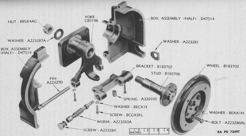
Seen from the opposite angle, the meshing of the worm and worm wheel can be conceptualized. The flexible shaft entered the gearbox via the aperture fitted with washer A223281. (Picture from TM 9-1334 Ordnance Maintenance--Stabilizers.)
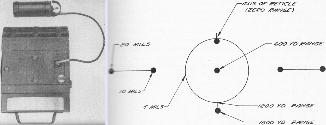
The 75mm gunner's periscope M1 was a simple mirror type with two mirrors facing each other at a 45° angle. The telescope M21 was clipped vertically to the periscope body so that its field of view was visible through the lower mirror, and an instrument light powered by a single flashlight battery could be used at night to illuminate the reticle. From left to right above are: the periscope M1 with the telescope dismounted; the telescope M21; the assembled periscope with telescope showing the clamp for the instrument light battery holder on the rear; the instrument light assembly; and finally, the assembled periscope, telescope, and instrument light. (Pictures from FM 23-95 75-mm Tank Gun M2 (Mounted in Medium Tank M3) and Conference on the 75mm M-2 Tank Gun.)
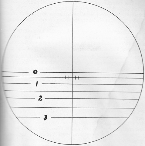
The reticle for the telescope M21 was designed for ammunition with a muzzle velocity of 1,850feet/sec (564m/s). The horizontal lines were based on elevations for ranges from 0 to 3,000 yards (0 to 2,700m), spaced every 500 yards (460m) and numbered every 1,000 yards (910m). The vertical tick lines on the 500-yard (460m) range line were 5 and 10 mil lead lines. When firing high-explosive ammunition after the gun had been boresighted for armor-piercing ammunition, the gunner needed to aim higher to account for the difference in muzzle velocity, e.g., aiming at 1,400 yards (1,300m) for a target 1,000 yards (910m) away or aiming at 700 yards (640m) for a target 500 yards (460m) away. (Picture from FM 23-95 75-mm Tank Gun M2 (Mounted in Medium Tank M3).)
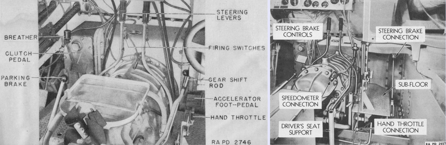
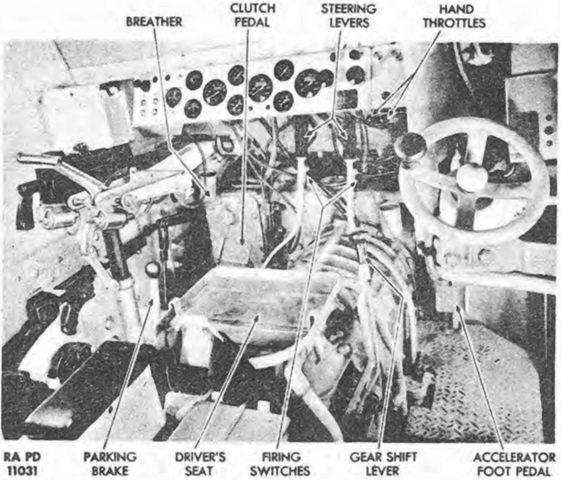
The driver's controls are detailed in this picture. The driver sat astride the transmission housing, with a foot pedal located on each side and the steering levers bent into a complex shape to provide clearance of the transmission housing. The steering levers used linkages to connect to the steering brakes at the outboard ends of the final drive and differential assembly. Note the firing switches for the driver's machine guns. (Picture from TM 9-750 Medium Tanks M3, M3A1, and M3A2 and TM 9-1750 Ordnance Maintenance--Power Train Unit, Three-piece Differential Case, for Medium Tanks, M3, M4, and Modifications.)
The driver's position is shown from the opposite side. The machine gun mount and aperture in the hull front are better seen. Early transmissions such as this one lacked an oil cooler, but a cooler was later added to the engine bulkhead, and hoses connected the transmission to the cooler. (Picture from TM 9-1750 Ordnance Maintenance--Power Train Unit, Three-piece Differential Case, for Medium Tanks, M3, M4, and Modifications.)
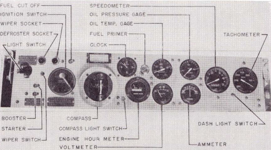
A closer look at the driver's instrument panel is provided here. (Picture from TM 9-750 Medium Tanks M3, M3A1, and M3A2.)
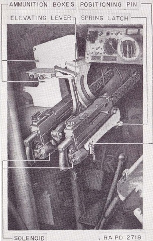
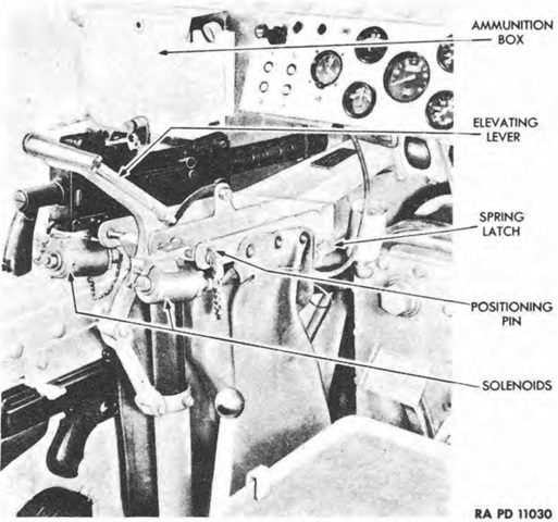
Details of the mounting of the twin hull machine guns are shown in this image. The guns could be fired by the conventional triggers or by the solenoids activated by the steering lever switches. Note that both ammunition boxes were staggered on the opposite side of the mount from the driver, and ammunition reached the guns via chutes. (Picture from TM 9-750 Medium Tanks M3, M3A1, and M3A2.)
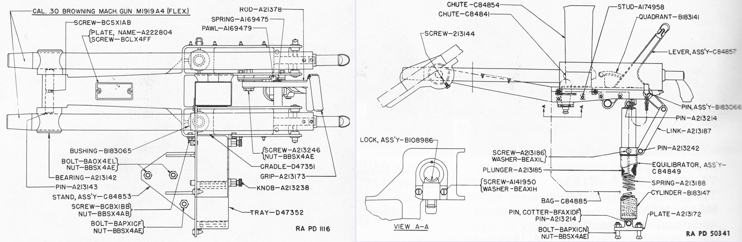
The bow machine gun mount M27 is sketched in plan view on the left and from the left side on the right. A bearing fixed in a pillow block that was attached to the hull provided the surface on which the machine gun cradle was rotated to adjust elevation. The guns were secured by a sub pintle and socket at the front and a pin at the rear. (Picture from Weapon Mounts for Secondary Armament.)
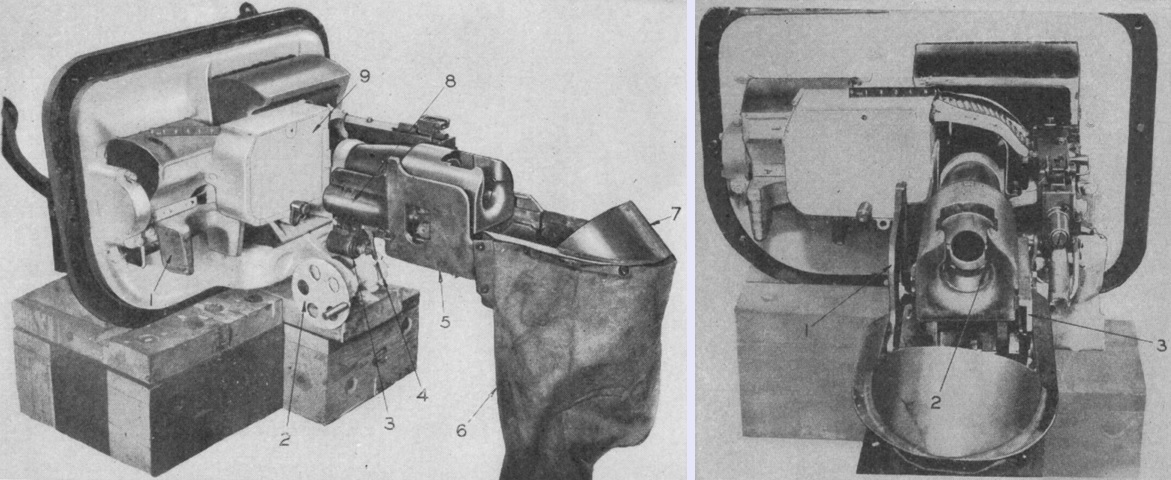
The 37mm gun M6 is seen in the combination gun mount M24 from the left rear and rear, respectively. The legend for the left image is: 1. Sight recess. 2. Elevating handwheel. 3. Solenoid firing device. 4. Trigger actuating mechanism. 5. Left guard. 6. Empty case bag. 7. Empty case deflector. 8. Closing spring housing. 9. Machine-gun ammunition chest.
The legend for the right image is: 1. Left guard. 2. Breechblock recess. 3. Breech operating mechanism. (Picture from FM 23-81 37-mm Gun, Tank, M6 (Mounted in Tanks).)
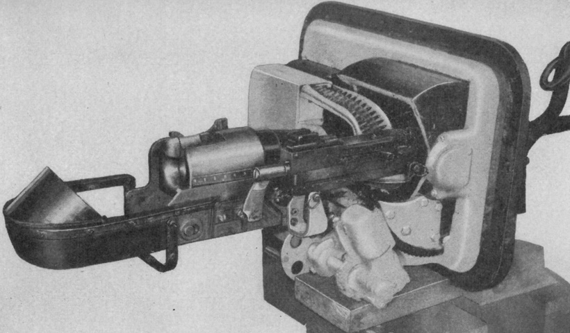
The right side of the gun mount is shown in this picture. The coaxial machine gun and its ammunition chute are visible. The 37mm gun M6 weighed ~700lb (~320kg). (Picture from FM 23-81 37-mm Gun, Tank, M6 (Mounted in Tanks).)
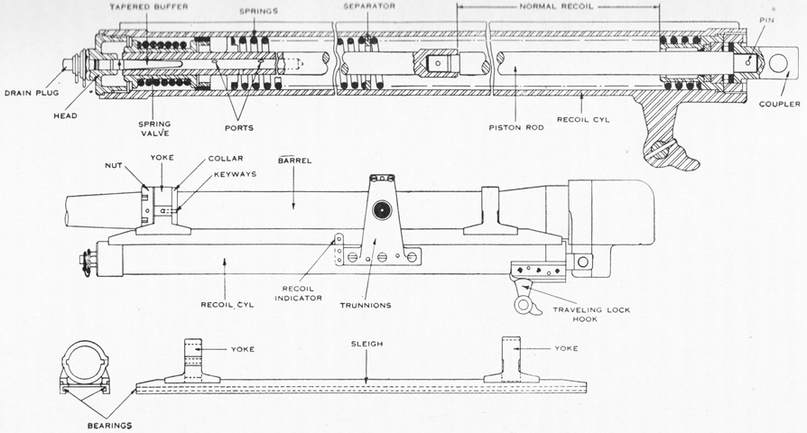
The 37mm gun's recoil mechanism was housed in the recoil cylinder. The recoil cylinder was constructed with rails that guided the gun sleigh in which the 37mm gun barrel was mounted. The recoil system was a hydrospring type, with a normal length of recoil of 6-8" (15-20cm). As the gun was forced to the rear upon firing, two counterrecoil springs were compressed, and the piston was forced through oil. The oil was forced through holes in the piston head and through ports in the forward end of the piston rod. The compressed counterrecoil springs then expanded, forcing the gun back into battery. Forward movement was controlled by valved closing of the holes in the piston head, further restricting the flow of oil, and the tapering of the buffer, which throttled the flow of oil as the gun returned forward and lessened the shock of the movement. The recoil cylinder held 5 pints (2.37L) of oil. (Picture from FM 23-81 37-mm Gun, Tank, M6 (Mounted in Tanks).)
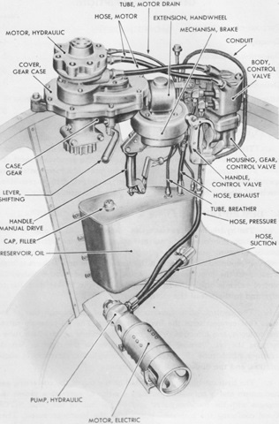
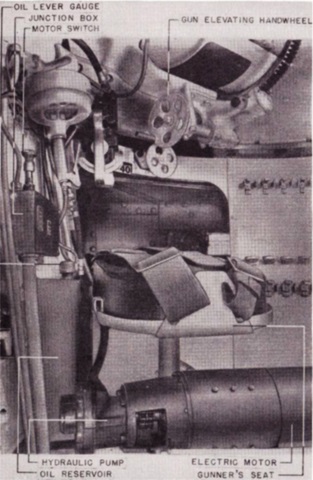
The hydraulic turret traversing mechanism is detailed in the left picture. The electric motor on the turret floor was directly connected to the hydraulic pump, which drew hydraulic oil from the reservoir on the turret basket wall. The pump delivered the oil under pressure to the inlet port of the manually-operated control valve, which governed the flow of oil through one of two tubes that were connected with the hydraulic motor. Depending on which tube through which the oil flowed, the hydraulic motor turned in one or the other direction. The hydraulic motor's shaft was splined through two pairs of spur gears to a pinion that engaged with the stationary ring gear on the tank hull. The valve control handle could be turned to the right or left to determine the tube through which the oil would flow, and therefore determine the direction of turret rotation. A manual traverse drive was also mounted along with a shifting lever that allowed the traverse to be changed from hydraulic to manual. On the right, the manual traversing gear mechanism and hydraulic control valve handle are detailed installed in the turret. (Picture from TM 9-1750H Ordnance Maintenance--Hydraulic Traversing Mechanism (Logansport) for Medium Tank M3 and Modifications.)
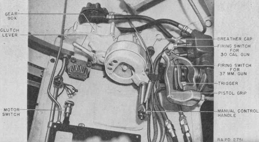
A similar view labels instead the controls for the operation of the turret and turret guns. (Picture from FM 23-81 37-mm Gun, Tank, M6 (Mounted in Tanks).)
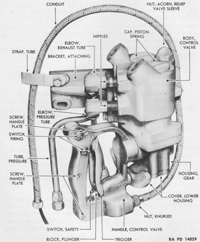
The hydraulic control valve is shown here. It was a manually-operated two-way piston valve that directed the flow of oil to one side or the other of the hydraulic motor, thereby rotating the turret in the desired direction. Electric switches for firing the turret guns were also mounted on the valve handle. It was necessary to squeeze the trigger, which flipped the safety switch, before the two firing switches were energized. The handle and trigger would return to their neutral positions if they were released, stopping turret traverse and de-energizing the firing switches. (Picture from TM 9-1750H Ordnance Maintenance--Hydraulic Traversing Mechanism (Logansport) for Medium Tank M3 and Modifications.)
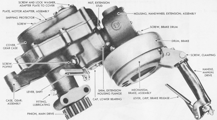
The manual traversing gear mechanism was geared to a pinion that meshed with the stationary ring gear on the tank hull. Two pairs of bevel gears and one pair of spur gears were used in the manual traversing mechanism. The shift lever was used to engage either the manual mechanism or hydraulic systems. (Picture from TM 9-1750H Ordnance Maintenance--Hydraulic Traversing Mechanism (Logansport) for Medium Tank M3 and Modifications.)
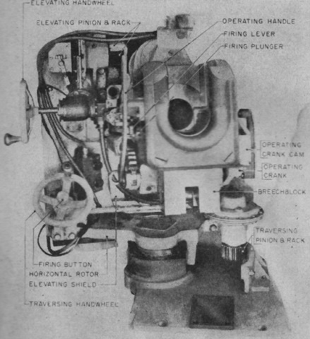
A broader view of the turret interior is labeled here. (Picture from TM 9-750 Medium Tanks M3, M3A1, and M3A2.)
The parts of the stabilizer for the 37mm gun are detailed here. (Picture from TM 9-750 Medium Tanks M3, M3A1, and M3A2.)
Two views of the gyro control gearbox used for the 37mm gun are provided in these pictures. The control link to the 37mm gun is present in the left image. (Picture from TM 9-1334 Ordnance Maintenance--Stabilizers.)
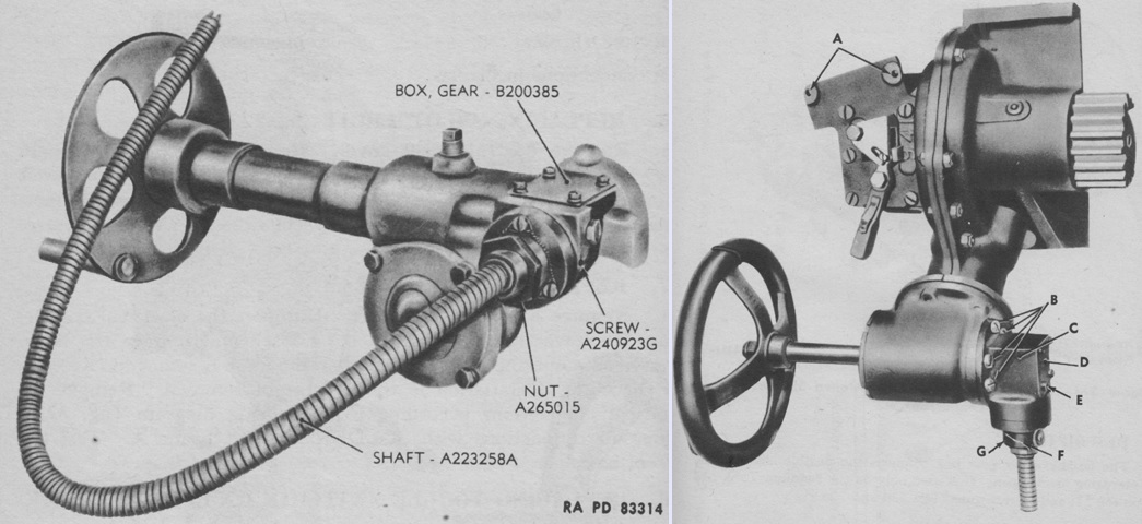
Unique to the stabilizer systems in the medium tank M3 were flexible shaft gearboxes that connected the flexible shafts to the hand elevation mechanisms of both the 37mm (left) and 75mm (right) guns. The legend for the 75mm gun image is: A. Disengaging switch mounting bolt holes. B. Screw. C. Box, gear. D. Plate, cover. E. Screw. F. Wire, locking. G. Nut. (Picture from TM 9-1334 Ordnance Maintenance--Stabilizers.)
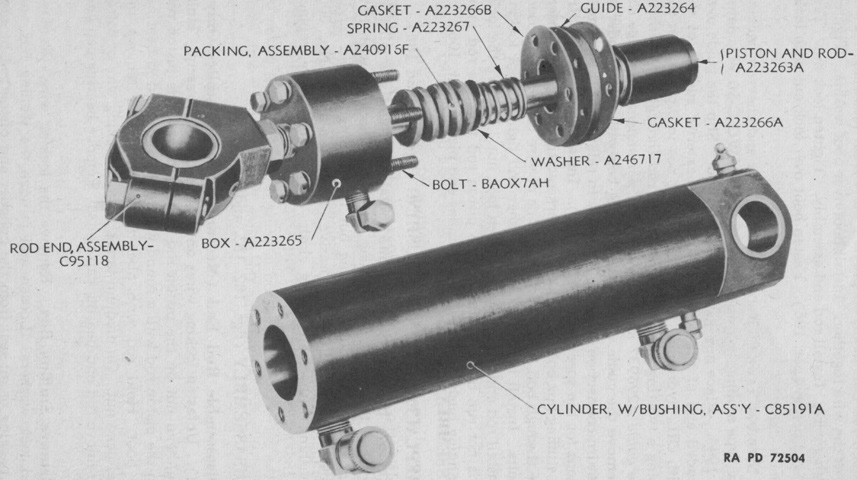
The piston and cylinder used for the 37mm gun stabilizer is shown here; a similar assembly was used for the 75mm gun. The piston rod was attached to the gun, while the cylinder was fastened to the turret. Two ⅜" (.953cm) oil lines from the oil pump allowed pressure to act on both sides of the piston. A ¼" (.64cm) line returned oil to the oil pump that leaked by the piston rod into the stuffing box. Very early in production, two bleeder valves were introduced to allow the removal of air without cracking the oil lines. The cylinder could be sealed with an oil seal or, as illustrated here, with chevron-type packing, which required an additional guide for the rod. (Picture from TM 9-1334 Ordnance Maintenance--Stabilizers.)
The periscope M2 and telescope M19 are seen on the left. The telescope was installed on the right-hand side of the periscope case, and the battery container of its instrument light clipped in above the sight when mounted in the tank. The telescope was not magnified, and some were issued with a simple crosshair similar to the telescopic sight M5A1. A later reticle is sketched on the right. The telescope M19A1 had an 11° field of view, a 4-15/16" (12.541cm) long tube, a 1¼" (3.18cm) diameter objective end, and a 0.64" (1.6cm) diameter eyepiece end. (Picture from FM 23-81 37-mm Gun, Tank, M6 (Mounted in Tanks).)
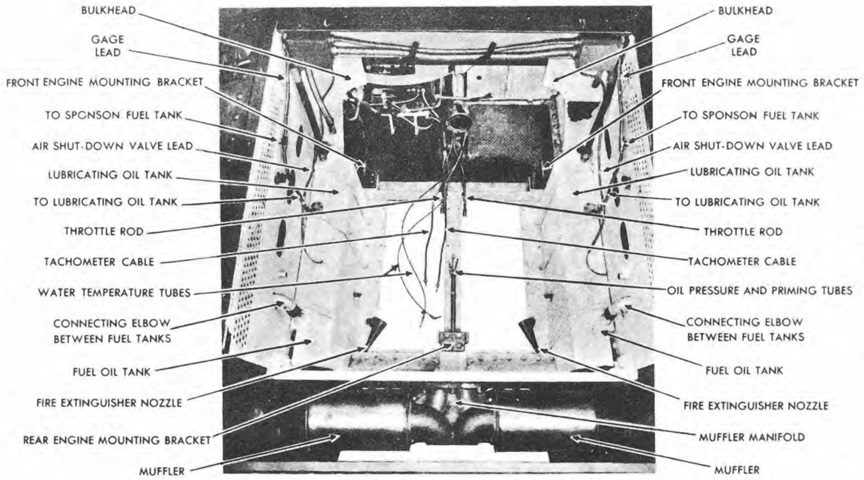
A top-down view of the engine compartment is the subject of this image. The front of the hull is to the top of the picture. (Picture from TM 9-750 Medium Tanks M3, M3A1, and M3A2.)
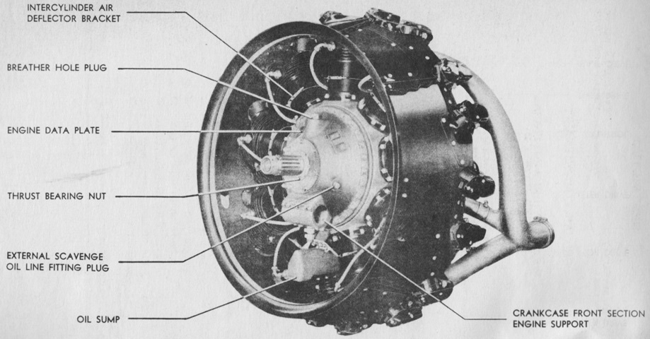
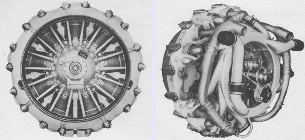
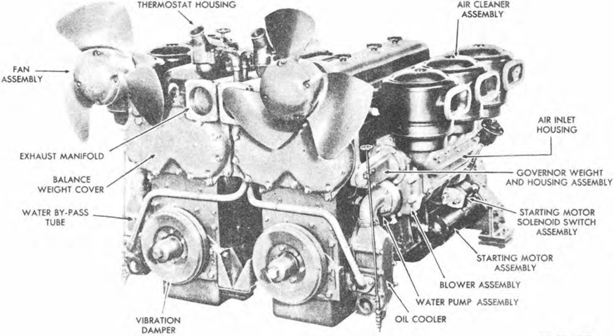
The R975 EC2 engine is seen from the left front. The flywheel end of the engine was considered the front, and the right and left sides were determined by looking at the engine from the rear. (Picture from TM 9-1751 Ordnance Maintenance--Wright Whirlwind Engine Model R975EC-2.)
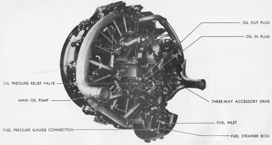
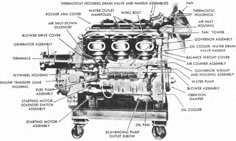
The engine is shown from the left rear. Bore and stroke were 5.00" and 5.50" (12.7cm and 14.0cm), respectively, for a displacement of 973in³ (15.9L). (Picture from TM 9-1751 Ordnance Maintenance--Wright Whirlwind Engine Model R975EC-2.)
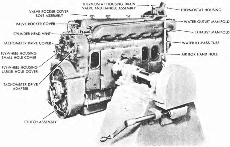
The engine's rear is labeled in this image. The top cylinder was number one, and the rest were sequentially numbered clockwise. Firing order was 1, 3, 5, 7, 9, 2, 4, 6, and 8. (Picture from TM 9-1751 Ordnance Maintenance--Wright Whirlwind Engine Model R975EC-2.)
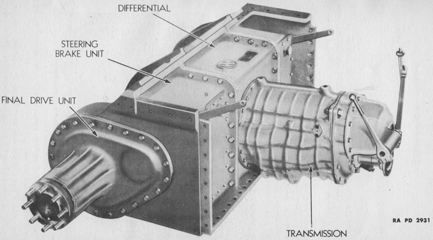
The power train was composed of two sprocket and hub assemblies, two final drive assemblies, two steering brake assemblies, and a transmission and parking brake assembly. The case was made of three sections bolted together. The steering brake lever arms are visible at the inside upper corners of the case assembly. Removing the 8,000lb (3,600kg) power train was a major service operation that required several hours. (Picture from TM 9-1750 Ordnance Maintenance--Power Train Unit, Three-piece Differential Case, for Medium Tanks, M3, M4, and Modifications.)
The transmission featured synchromesh second through fifth gears, and constant mesh for first and reverse. A parking brake was built into the transmission, and was actuated by the lever to the left of the image. The gearshift lever is on the opposite side of the transmission. (Picture from TM 9-750 Medium Tanks M3, M3A1, and M3A2.)
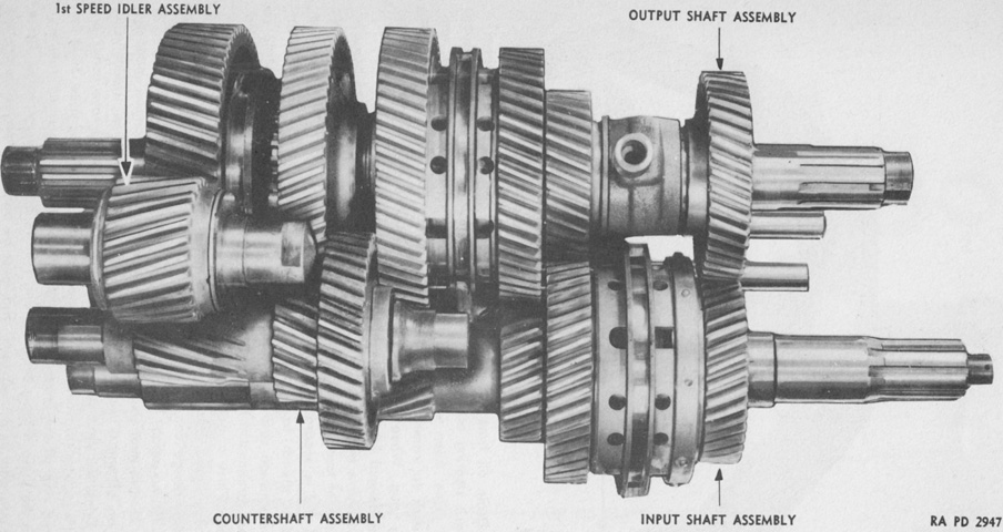
The gear assemblies in the transmission are shown here dismounted. Synchronizers are visible on the input shaft between the rightmost pair of gears, and at the center of the output shaft. (Picture from TM 9-1750 Ordnance Maintenance--Power Train Unit, Three-piece Differential Case, for Medium Tanks, M3, M4, and Modifications.)
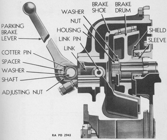
A cross-section of the parking brake has been drawn. The parking brake lever moved the brake shoe in and out of engagement, and the mechanism included a lock. (Picture from TM 9-1750 Ordnance Maintenance--Power Train Unit, Three-piece Differential Case, for Medium Tanks, M3, M4, and Modifications.)
Later power train units with oil coolers mounted on the engine bulkhead used a tube to transport oil from the differentials to the transmission sump. The oil was then drawn into the transmission oil pump which forced it through a drilled hole in the transmission case into a hose that connected to the oil cooler. The oil was then returned to the transmission through the sleeve, where it was forced through the collar, into the output shaft, and through holes to each gear bearing, from which it dripped onto the gears. The lower section of the transmission was submerged in oil, and the oil was splashed onto all transmission parts as the gears rotated. The oil then passed through openings in the transmission case front and returned to the differential. (Picture from TM 9-1750 Ordnance Maintenance--Power Train Unit, Three-piece Differential Case, for Medium Tanks, M3, M4, and Modifications.)
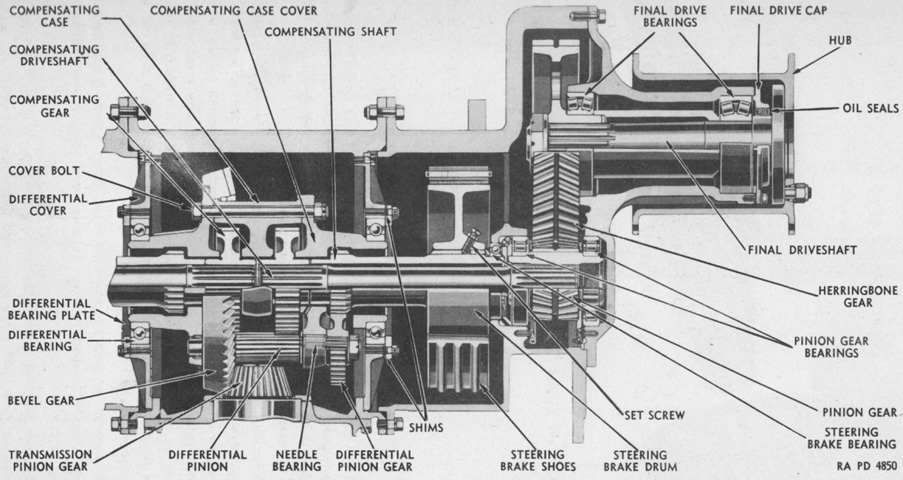
The controlled, or compensating, differential is diagrammed attached to the right-side steering brake. Bolts securing the three-piece case can be seen, along with how the three pieces fit together. The bevel gear operated one set of gears and a compensating shaft on each side to steer and brake the tank, and another set of gears and a compensating drive shaft on each side to drive the tank. A steering brake drum was carried on each compensating shaft; when a brake was actuated and that compensating shaft consequently slowed or stopped, the track on that side also slowed, causing the tank to turn to that side. Slowing or stopping both compensating shafts slowed or stopped the tank. Power left the differential to the final drives via the compensating drive shafts. (Picture from TM 9-1750 Ordnance Maintenance--Power Train Unit, Three-piece Differential Case, for Medium Tanks, M3, M4, and Modifications.)
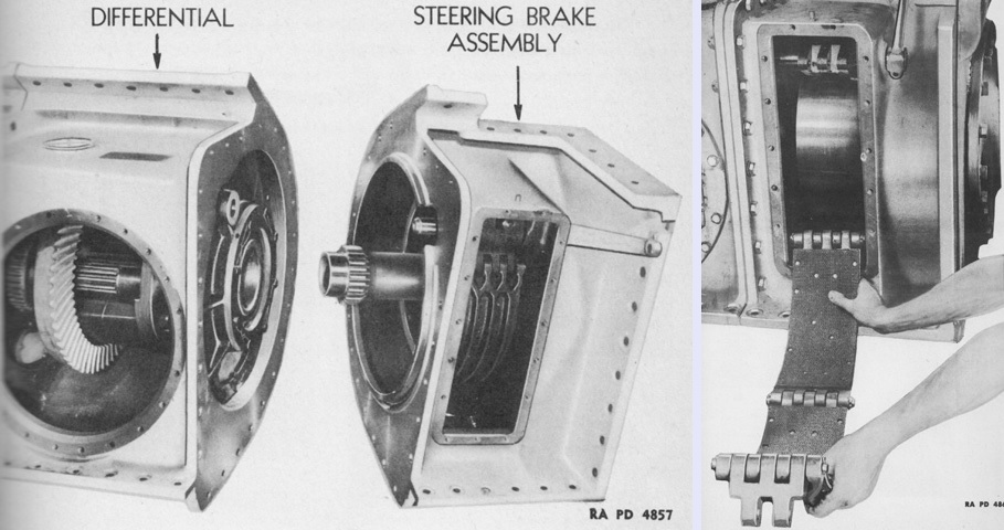
On the left, the steering brake assembly has been removed from the differential assembly after the connecting bolts have been removed. The lower and outer flanges were secured by 1⅛" (2.858cm) bolts, while the inner flange was held by 1" (2.5cm) bolts. Note that armor flange of the right-side steering brake assembly did not extend all the way across; this provided clearance for the 75mm gun installation. On the right, the right-side steering brake shoe is being pulled out of the housing. The brake lining was .3125" (.7938cm) thick when new, and needed to be drilled for rivets when installed. (Picture from TM 9-1750 Ordnance Maintenance--Power Train Unit, Three-piece Differential Case, for Medium Tanks, M3, M4, and Modifications.)
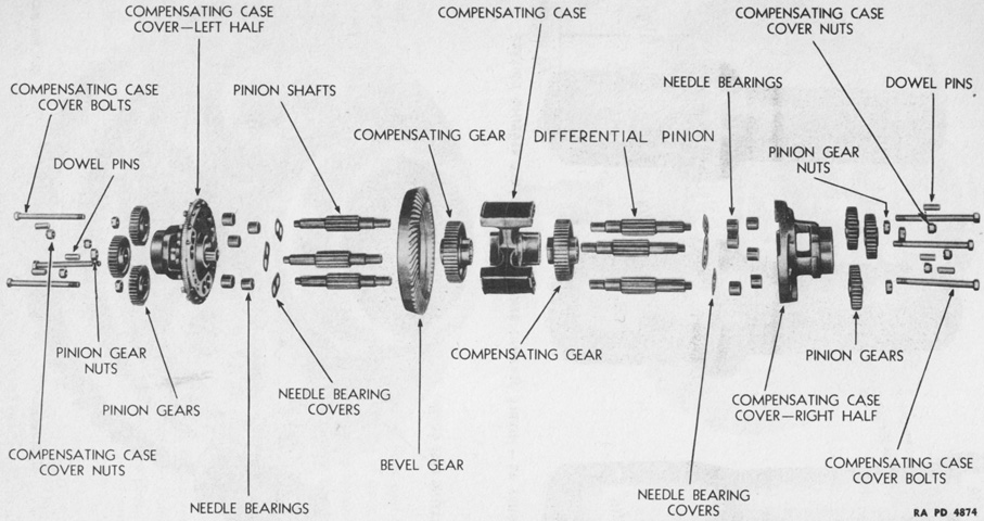
An exploded view of the differential is provided here. (Picture from TM 9-1750 Ordnance Maintenance--Power Train Unit, Three-piece Differential Case, for Medium Tanks, M3, M4, and Modifications.)
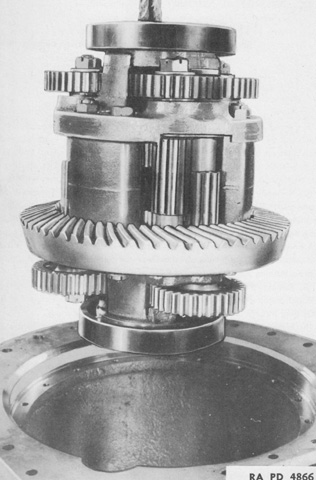
The assembled differential is being removed from its case by a rope. (Picture from TM 9-1750 Ordnance Maintenance--Power Train Unit, Three-piece Differential Case, for Medium Tanks, M3, M4, and Modifications.)
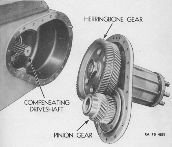
The final drives used herringbone gears, with power entering the final drive assembly from the compensating driveshaft via the pinion. Power was then transferred to the drive sprockets through the herringbone gears and final drive shafts. (Picture from TM 9-1750 Ordnance Maintenance--Power Train Unit, Three-piece Differential Case, for Medium Tanks, M3, M4, and Modifications.)
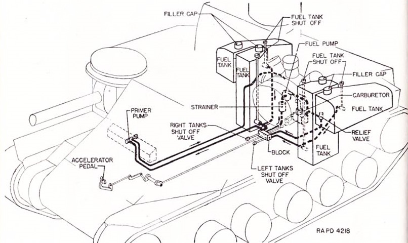
Four fuel tanks for the main engine were located in the hull rear. The auxiliary generator was provided with its own 2.5gal (9.5L) fuel tank in the left rear of the fighting compartment. The 2-cycle auxiliary generator engine required ⅜ pint (180mL) of SAE 50 or 60 engine oil to be mixed with each gallon (3.8L) of gasoline. (Picture from TM 9-750 Medium Tanks M3, M3A1, and M3A2.)
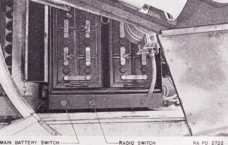
Two 12-volt storage batteries were connected in series to provide for the 24-volt electrical system. The battery compartment was behind the driver on the hull's left side under the turret basket. The radio switch had its own connection to the battery. (Picture from TM 9-750 Medium Tanks M3, M3A1, and M3A2.)
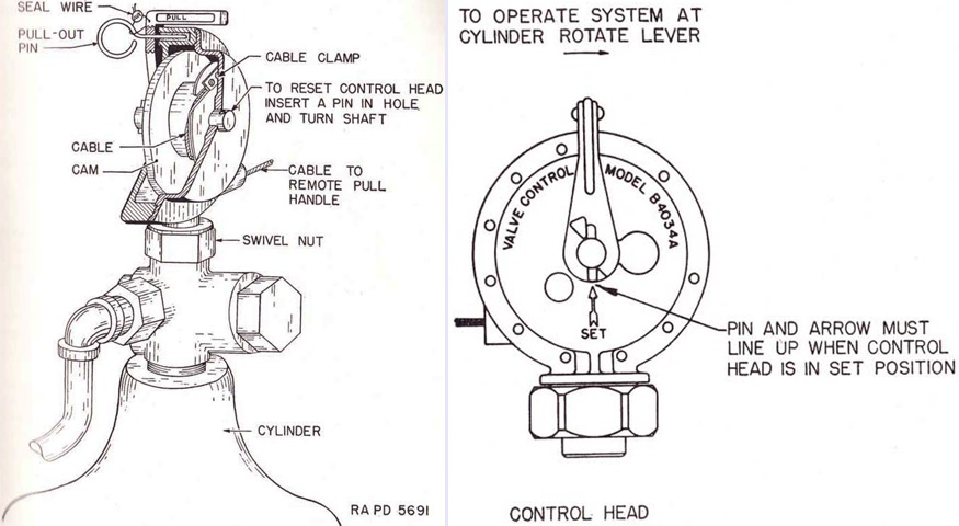
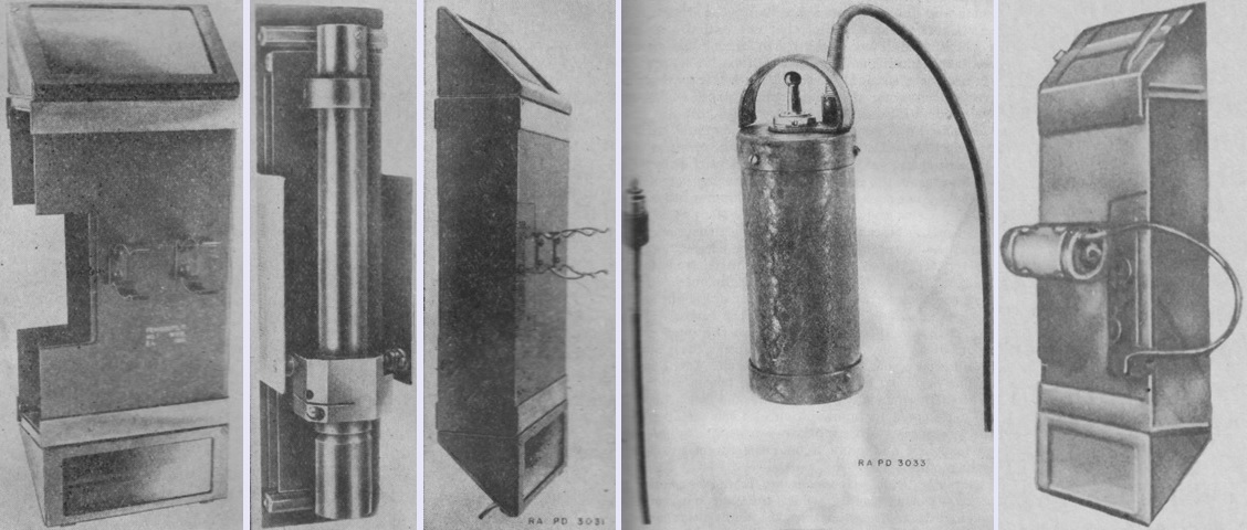
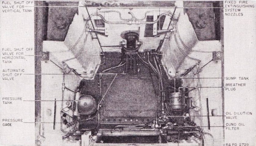
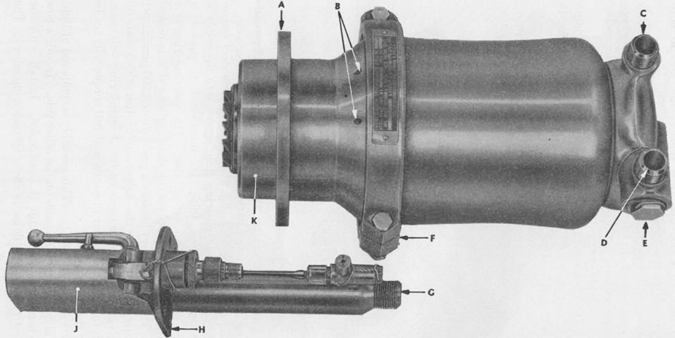
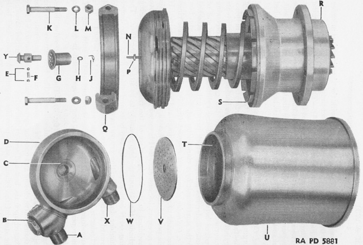
Two cylinders each containing 10lb (4.5kg) of CO2 comprised the fixed fire extinguishing system. These were routed to the engine compartment, and two 4lb (2kg) portable fire extinguishers were carried for fires in other locations. The fixed system was entirely manual; control handles were provided at the turret basket bracket, near the fuel gages, and on the exterior of the top of the engine compartment. If a second cylinder needed to be actuated, another handle would have to be pulled. The fixed extinguisher control head and cylinder valve are shown on the left, with the control head detailed on the right. (Picture from TM 9-750 Medium Tanks M3, M3A1, and M3A2.)
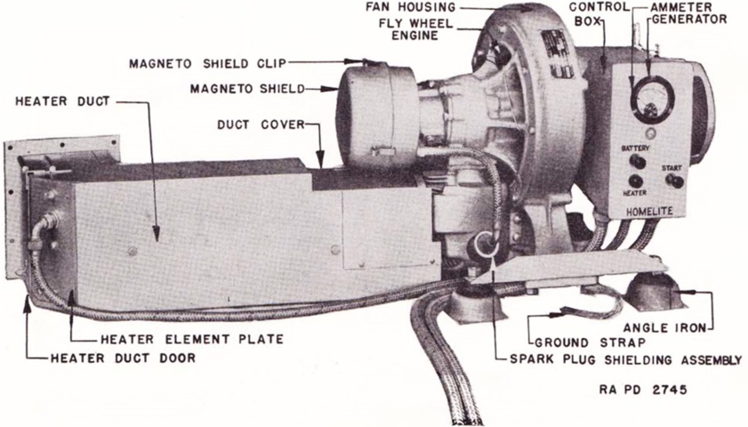
The tank's auxiliary generator, the Homelite heater-generator HRH-28, was mounted in the left rear corner of the fighting compartment. It supplied 1500 watts, 30 volts DC for charging the tank's batteries; and a heater element preheated the main engine as well as provided heat for the crew. The Homelite HR-28 electrical generator was driven by a small 3400-3600rpm, 2-cycle, single-cylinder Homelite HR gasoline engine. (Picture from TM 9-750 Medium Tanks M3, M3A1, and M3A2.)
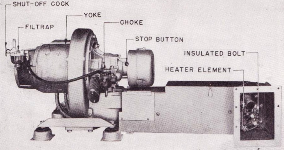
The rear of the auxiliary generator is shown here. It was desirable to run the generator when the turret was being operated via hydraulic power or when the guns were being fired, since all except the cupola .30cal machine gun were triggered via solenoids. (Picture from TM 9-750 Medium Tanks M3, M3A1, and M3A2.)
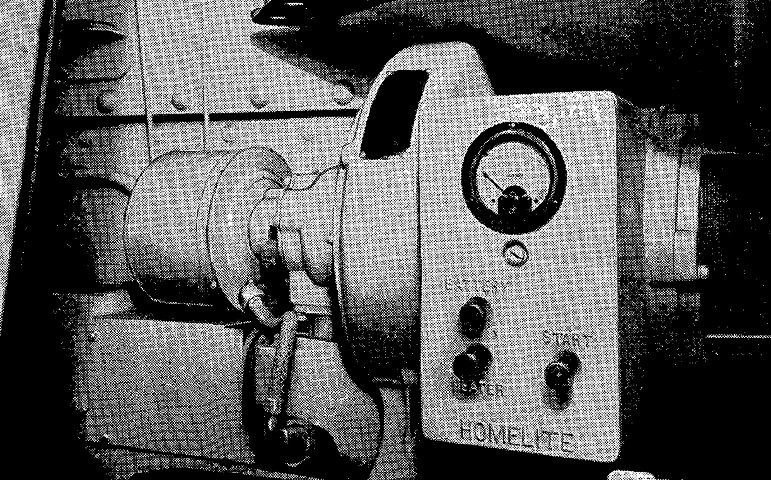
The auxiliary generator is installed in the tank in the left image. The control box had buttons for START, BATTERY, and HEATER. The battery and heater buttons used the generator towards charging the vehicle batteries and powering the heater element, respectively, while the start button started the generator engine electrically. If necessary, a starting rope could also be used to start the engine after removing the magneto shield. On the right, the fuel filler for the auxiliary generator engine's fuel tank is revealed. (Picture from TM 9-1752 Auxiliary Generator (Homelite Model HRH-28) for Medium Tank, M3.)
The different turret on this vehicle marks it as a British Grant I. The British did not use the turret machine gun cupola and placed a radio in the bustle of the turret of the Grant. The British turret was longer and wider as a consequence. This vehicle retains the hull side doors, but the hull machine gun ports have been plugged. The aperture for the 2" smoke mortar is visible on the right side of the turret roof. The tracks on this tank are the WD 212, also called WE 210, which was the name of an assembly of four shoes. The double-I pattern on the track provided enhanced traction compared to the smooth face of the T41 track.
Both hull machine gun mounts are present on this tank, and the bearings through which the guns were mounted can be seen.
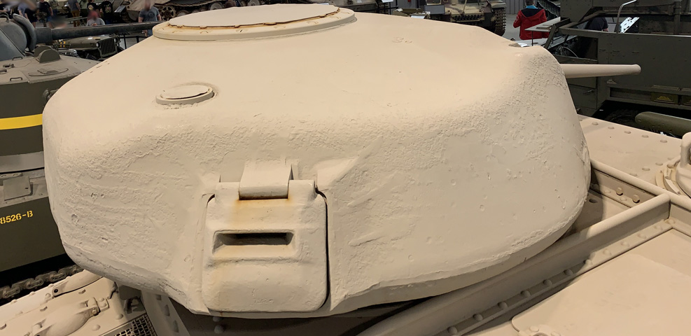
The profile view of the British turret shows the lengthened radio bustle at the rear.
The turret hatch and radio antenna mount have been blanked off on this machine, but their locations are still apparent in the roof.
The quick-fix exhaust modification scheme that was instituted before the final production design could be brought online is installed on the tank on the left, and can be contrasted to the final exhaust solution on the tank on the right. With the quick-fix solution, external air cleaners were mounted, but the exhausts remained in their original location while exchanging the earlier pepperpot style for straight pipes ending in fishtails.
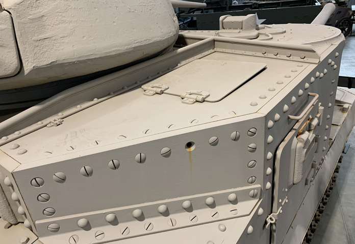
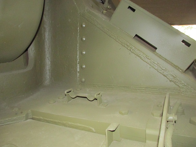
Without the hull ventilator behind it, the roof hatch would be able to lie flat when opened. The slotted screws securing the armor panel that facilitated work on the 75mm gun can again be seen.
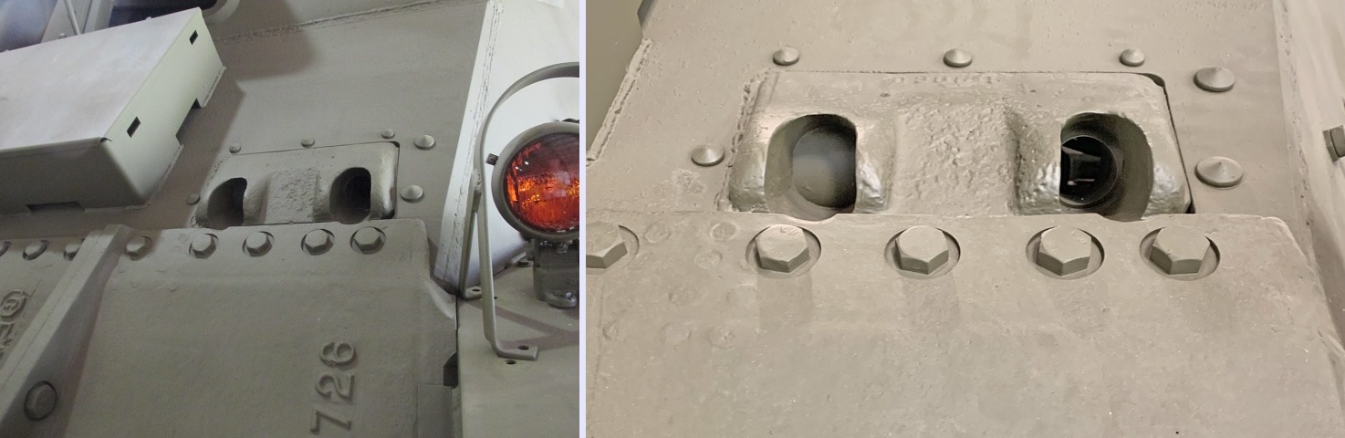
Rivets of different sizes secured plates of different thicknesses.
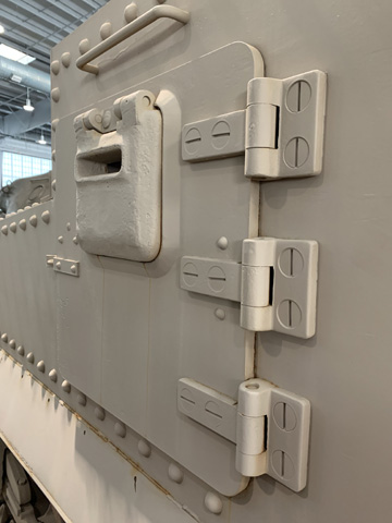
The heavy hinges and screws that secured the side door are obvious here. A grab handle was provided above the door.
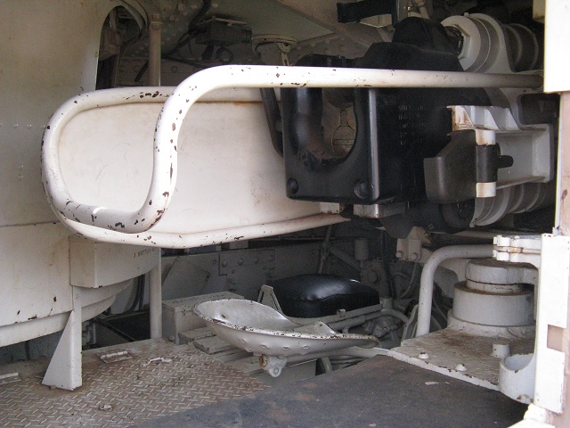
Two views of the 75mm gun while looking through the open starboard side door are provided. The breech of the 75mm gun and the 75mm gunner's seat are visible in the left image. The driver's black padded seat is beyond the 75mm gunner's seat, and the turret shield is to the 75mm gunner's left rear. On the right can be seen the mount for the gunner's periscope M1 and the piston for the gyrostabilizer, however the rest of the stabilizer equipment is missing
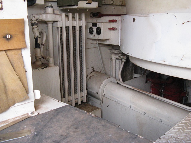
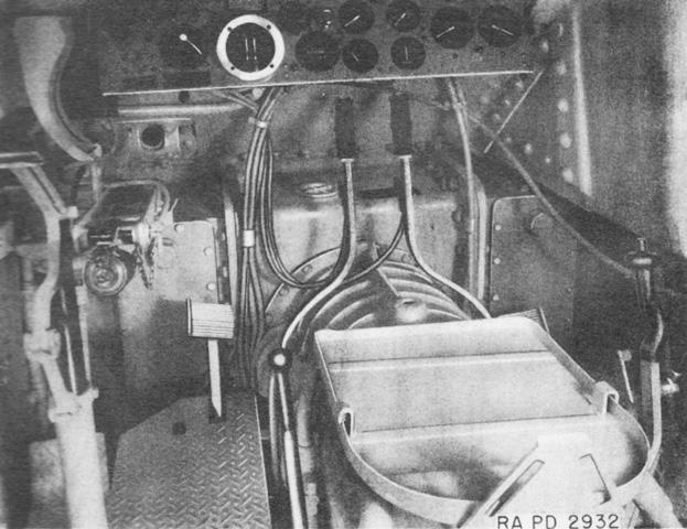
The interior of the tank behind the 75mm gunner is shown here. The engine propeller shaft runs beneath the turret, and an oil cooler and oil tank are attached to the bulkhead. The two gauges facing us above the propeller shaft are fuel gauges, and the red handles are for discharging the carbon dioxide cylinder fire extinguishers. The red fire extinguisher cylinders themselves can be seen under the turret basket.
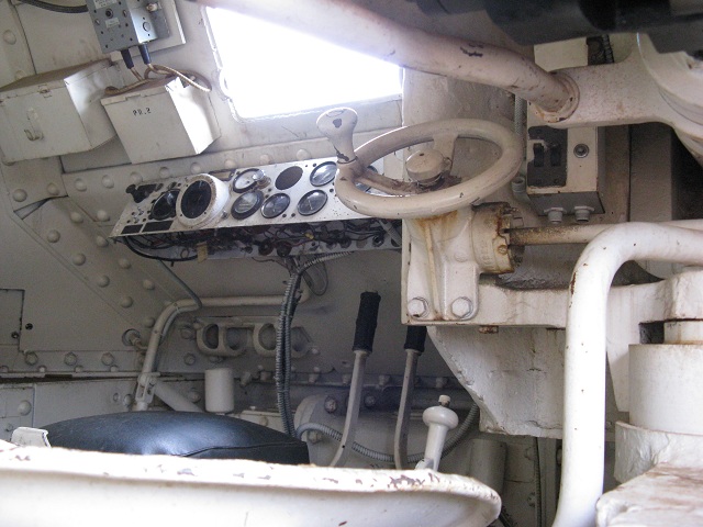
Looking beyond the 75mm gun, we can see the driver's controls and instrument panel. The steering levers are in front of his seat, and the white gear shift lever is to his right. The handwheel on the right of the image is for traversing the 75mm gun, and this handwheel also contained the solenoid firing button. The riveted construction of the vehicle is evident on the inside as well, and the rivets had the unfortunate tendency to break apart when hit and ricochet around the tank's interior.
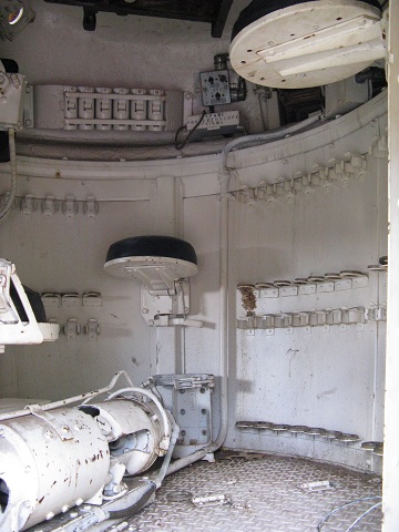
This image is looking into the 37mm turret from the port hull side door. The tank commander's seat is at the top right corner of the picture, the 37mm loader's seat is directly across the turret, the rear of the 37mm gunner's seat can be glimpsed to the left of the frame, and 37mm ammunition racks line the turret walls.
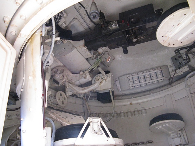
The turret crew's positions relative to each other can be better seen here. The gunner's elevation handwheel has a black handle and is positioned parallel to the 37mm gun, and the black gyrostabilizer control unit can be seen across the turret near the turret ring. Since the 2" smoke mortar is not present, sunlight can be seen streaming in through its open mount to the far side of the 37mm gun.
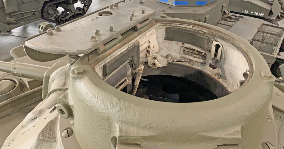
Details of the commander's hatch are shown here. A rotatable periscope mount is allowing light through.
This cast, smooth-lined M3A1 is armed with the short-barreled 75mm gun M2, and since neither it nor the 37mm guns are fitted with counterweights, this tank also lacks stabilization. This tank also has the early suspension bogies which have the return roller on top of the brace. The aperture to the left of the 37mm gun was for the gunner's periscope. The machine gun in the cupola emerged from the right opening; the left was for a vision slot. There are antenna mounts behind the turret and behind the front hull pistol port. (Picture from Tank Data, vol. 2.)
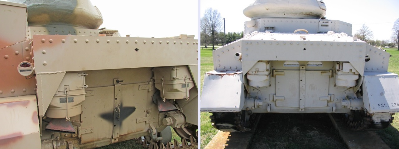
The hull roof door is visible on the rear slope of the 75mm gun sponson, and is hinged to the front on this early tank. The hull side door is also present. (Picture from FM 30-40 Military Intelligence Identification of United States Armored Vehicles.)
The smooth cast hull can be seen from the rear. Engine access doors are present in the lower rear hull, and pepperpot-style exhausts flank the engine access doors. (Picture from FM 30-40 Military Intelligence Identification of United States Armored Vehicles.)
Tool stowage remained similar to the riveted hull types. This early tank has not been fitted with the rooftop ventilating blowers. (Picture from FM 30-40 Military Intelligence Identification of United States Armored Vehicles.)
The front and rear of a T-1400-3 diesel engine are seen here; it differed from the T-1400-2 by having a cylinder barrel with an 8 ⅜" (21.27cm) outside diameter compared to the earlier engine's 7 ½" (19cm) outside diameter. Bore and stroke were 5 ¾" and 6" (14.6cm and 15cm), respectively, for a displacement of 1,402in³ (22.97L). Its overall diameter was 53" (135cm), and length with Coffman starter and 30-watt generator installed was 41 ⅞" (106.36cm). Compression ratio was 14:1, and it produced 350-375bhp at 2,200rpm. (Picture from TM 9-1750E Ordnance Maintenance--Guiberson Diesel T1400 Engine, Series 3, for Medium Tanks M3 and M4 and Related Gun Motor Carriages.)
The T-1400 used a starting system shared with Guiberson's light tank diesel radial engines that spun the engine by gas pressure generated from the firing of a cartridge. The starter unit is shown at the top, with the breech assembly below. A. Starter unit mounting flange. B. Vent holes. C. Intake connection. D. Exhaust connection. E. Safety disk holder assembly. F. Cylinder clamp split ring set. G. Intake connection. H. Breech assembly mounting flange. J. Type A breech assembly. K. Type L4A starter unit. (Picture from TM 9-1731 Ordnance Maintenance--Breeze Cartridge Starter for Radial Diesel Engines.)
The internal parts of the starter unit are labeled here. A. Exhaust tube connection. B. Safety disk holder assembly. C. Exhaust valve seat. D. Fuel combustion chamber. E. Exhaust valve ball. F. Exhaust valve spring. G. Exhaust valve housing. H. Spacer. J. Clip. K. Cylinder clamp ring bolt. L. Plain washer. M. Nut. N. Exhaust valve control bolt. P. Exhaust valve control bolt nut. Q. Cylinder clamp ring. R. Housing assembly. S. Hub assembly. T. Shoulder. U. Cylinder. V. Perforated disk. W. Combustion chamber gasket. X. Intake tube connection. Y. Exhaust valve. (Picture from TM 9-1731 Ordnance Maintenance--Breeze Cartridge Starter for Radial Diesel Engines.)
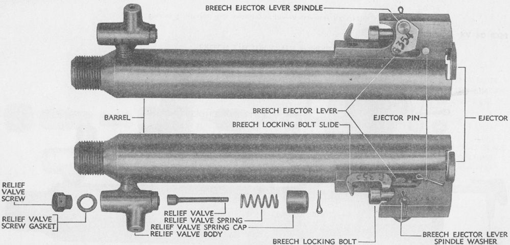
The breech's barrel assembly and relief valve are detailed in this image. (Picture from TM 9-1731 Ordnance Maintenance--Breeze Cartridge Starter for Radial Diesel Engines.)
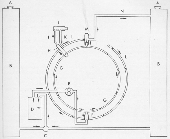
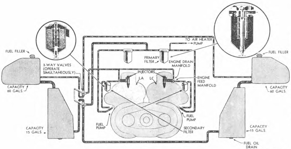
Fuel oil was forced from the tanks and through the filter by the fuel supply pump. From there, a one-way check valve permitted entry into the fuel channel, which was a drilled passage in the rear mounting section of the crankcase that connected the injection pump mounting holes. The channel supplied each fuel injection pump with fuel that was then passed through the injectors into the combustion chambers. A. Tank vent. B. Fuel tank. C. Tank valve. D. Fuel oil filter. E. Supply pump. F. One way check valve. G. Fuel channel. H. Injection pump. I. Pressure line. J. Injector. K. Drip line. L. Fuel return ring. M. Regulator valve. N. Return line. (Picture from TM 9-1750E Ordnance Maintenance--Guiberson Diesel T1400 Engine, Series 3, for Medium Tanks M3 and M4 and Related Gun Motor Carriages.)
The M3A2 was the first of the series to feature a welded hull. The sharp lines and lack of riveting are obvious when compared with the tanks above. (Picture from Tank Data, vol. 2, and Modern Ordnance Materiel.)
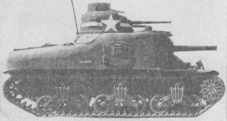
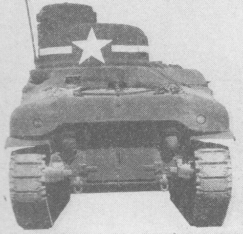
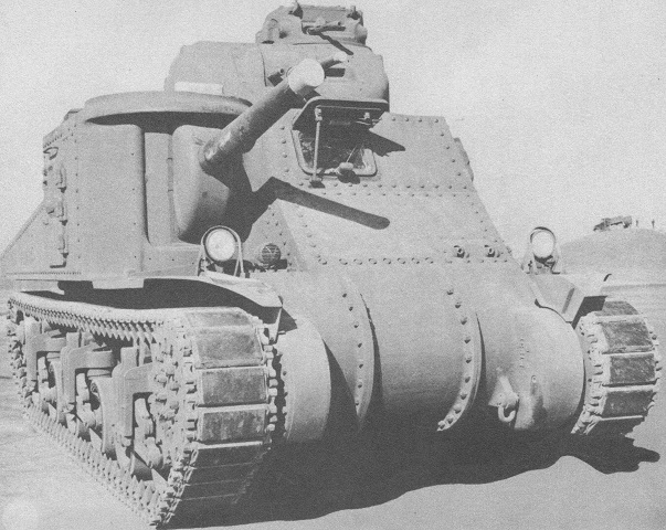
Most of the identifying features for M3A5 are on the rear of the vehicle, since the major difference between M3A5 and M3 is that the former is powered by twin diesel engines rather than the radial gasoline engine. This tank is not fitted with stabilization since it lacks counterweights under the 37mm gun and around the end of the short 75mm gun M2's barrel. It also is running on the T49 parallel bar steel tracks. (Picture from Development of Armored Vehicles, volume 1: Tanks.)
The modified engine deck used with the diesel engines is visible from this angle. The lack of hinges on the side door indicates that they have been welded shut, but the pistol port was retained in the right-side door. Roof ventilators were installed in the turret next to the cupola, behind the hull roof hatch, and the third, on the left-front corner of the hull, is partially obscured by the 37mm gun tube. (Picture from TM 9-753 Medium Tanks M3A3 and M3A5.)
The rear configuration necessarily changed with the different powerplant installation. The rear armor was extended to protect the radiators, and an exhaust deflector was added below the air outlet aperture. (Picture from TM 9-753 Medium Tanks M3A3 and M3A5.)
This tank also has its side door welded up, and the pistol port has been eliminated on this side. The engine air inlet grille is open, and can be seen behind the stowage box. The cylindrical counterweight for the stabilizer is mounted under the 37mm gun, and the short barrel of the 75mm gun M2 has a counterweight fitted around it in order to balance it for the stabilizer. Note the pistol port in the right hull side remained even after the doors had been eliminated.
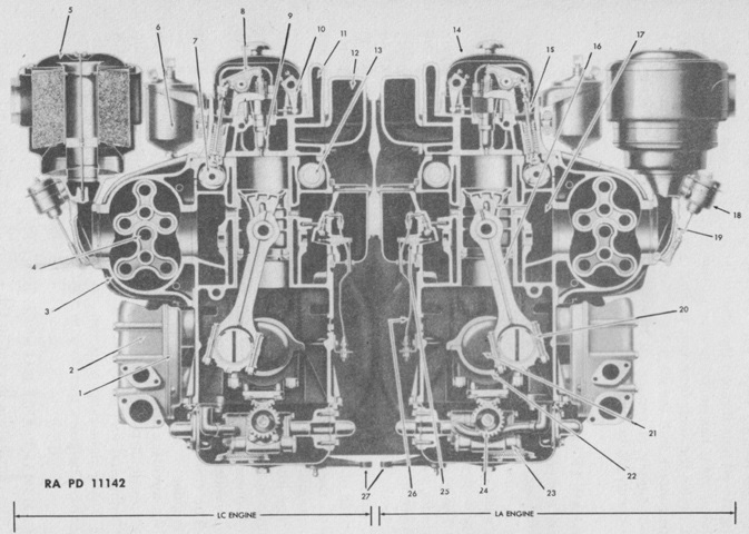
The different internal arrangement necessitated by the twin diesel engines can be gleaned when this image is compared with the cross-section of the M3 above. (Picture from Tank Data, vol. 2.)
The driver's position is seen here. Two hand throttles were provided, one for each engine, and they were moved from the floor to the instrument panel. (Picture from TM 9-753 Medium Tanks M3A3 and M3A5.)
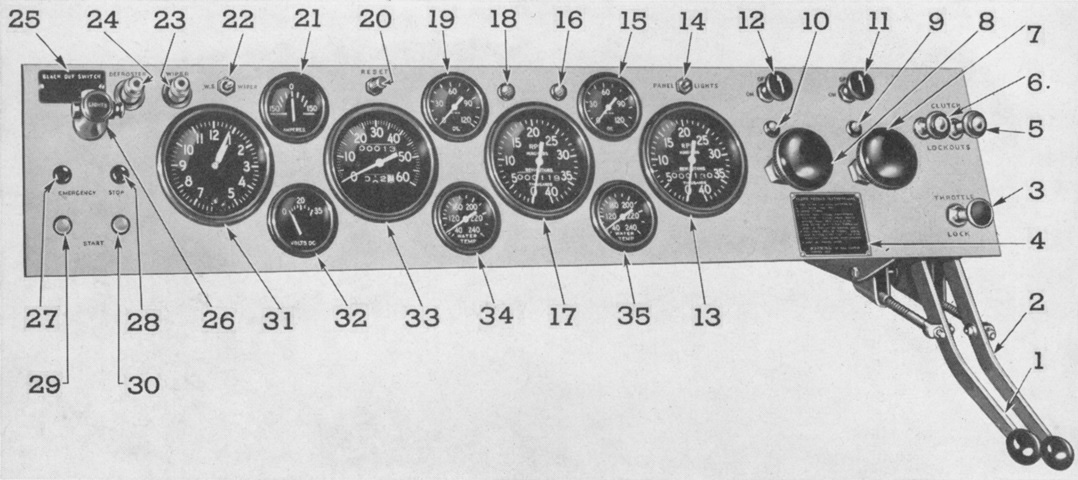
The driver's instrument panel is labeled here. 1. Throttle control--LC engine. 2. Throttle control--LA engine. 3. Throttle lock. 4. Instruction plate--air heater. 5. Clutch lockout--LA engine. 6. Clutch lockout--LC engine. 7. Air heater pump--LA engine. 8. Air heater pump--LC engine. 9. Tell-tale (warning light)--air heater switch--LA engine. 10. Tell-tale (warning light)--air heater switch--LC engine. 11. Air heater switch--LA engine. 12. Air heater switch--LC engine. 13. Tachometer--LA engine. 14. Switch--panel lights. 15. Pressure gage--lubricating oil--LA engine. 16. Tell-tale (warning light)--low lubricating oil pressure--LA engine. 17. Tachometer--LC engine. 18. Tell-tale (warning light)--low lubricating oil pressure--LC engine. 19. Pressure gage--lubricating oil--LC engine. 20. Reset lever--speedometer. 21. Ammeter. 22. Switch--windshield wiper. 23. Outlet--windshield wire lead. 24. Outlet--defroster lead. 25. Instruction plate--lights. 26. Switch--running lights. 27. Switch button--emergency stop--LC engine. 28. Switch button--emergency stop--LA engine. 29. Switch button--starting--LC engine. 30. Switch button--starting--LA engine. 31. Clock. 32. Voltmeter. 33. Speedometer. 34. Gage--water temperature--LC engine. 35. Gage--water temperature--LA engine. (Picture from Model 6046 Series 71 Twin 6 Cylinder Diesel Engine Maintenance Manual.)
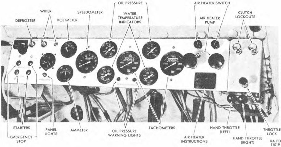
The instrument panel is shown installed. The clutch lockouts enabled one engine or the other to be locked out so that the tank could operate on one engine if needed. (Picture from TM 9-753 Medium Tanks M3A3 and M3A5.)
Even after the elimination of one of the hull machine guns, the twin mount was retained including the solenoid for the firing mechanism. (Picture from TM 9-753 Medium Tanks M3A3 and M3A5.)
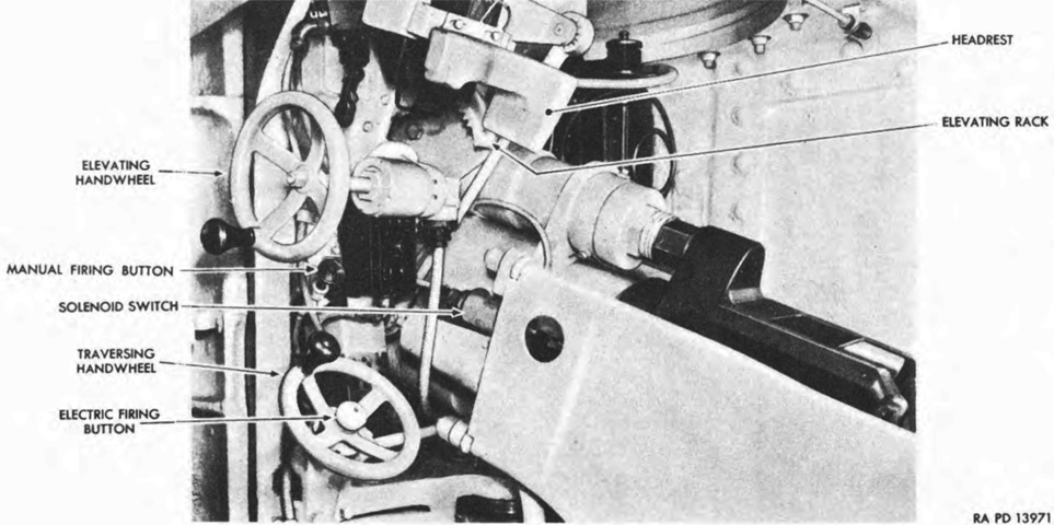
The 75mm gunner's controls are shown in this image. (Picture from TM 9-753 Medium Tanks M3A3 and M3A5.)
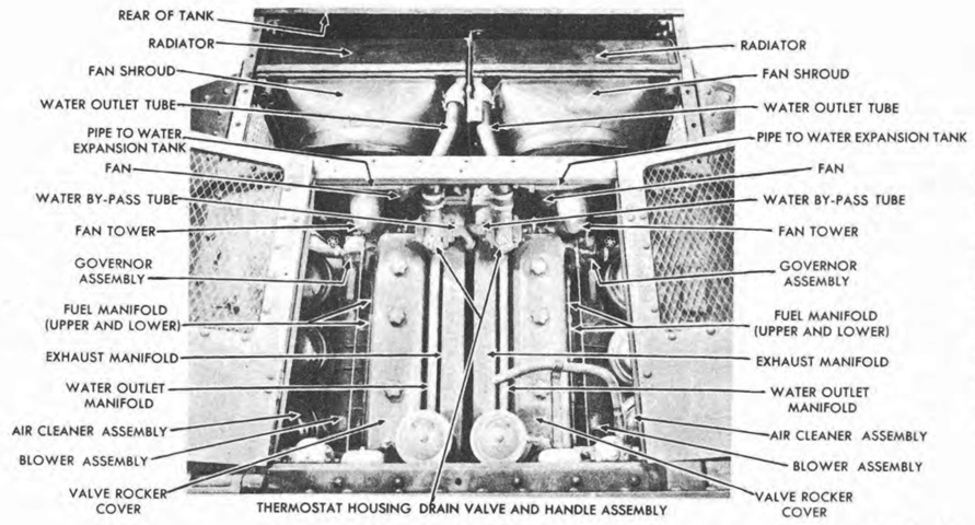
The engine compartment doors have been opened, showing the powerplant looking towards the vehicle's rear. (Picture from TM 9-753 Medium Tanks M3A3 and M3A5.)
The installed powerplant is seen from the opposite angle. (Picture from TM 9-753 Medium Tanks M3A3 and M3A5.)
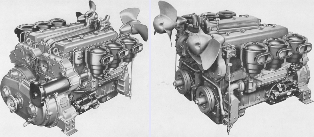
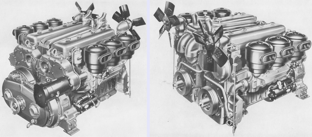
A ¾ front and rear view of the GM 6046 power unit are provided on the left and right, respectively. The power from each engine was sent through its drive shaft and gear to a common driven gear which in turn drove the propeller shaft. The individual engines were designated model 671LA24M (right-side engine) and 671LC24M (left-side engine), abbreviated LA and LC, respectively. The power unit weighed 4,340lb (1,970kg), and the weight as installed including the radiators, filter panel, voltage and current regulator, propeller shaft, fan shrouds, and exhaust mufflers was 4,855lb (2,202kg). The engines' bore and stroke were 4.25" and 5" (10.8cm and 12.7cm), respectively, for a displacement of 425in³ (6.96L) for each engine. The nominal compression ratio was 16:1. This early engine has the original three-blade cast cooling fans. Note also the single generator, which is the black cylinder protruding horizontally from the near corner. (Picture from Model 6046 Series 71 Twin 6 Cylinder Diesel Engine Maintenance Manual.)
The rear of the powerplant is labeled here. (Picture from TM 9-753 Medium Tanks M3A3 and M3A5.)
The powerplant is shown from the side. (Picture from TM 9-753 Medium Tanks M3A3 and M3A5.)
The LA engine is isolated here on an engine stand. (Picture from TM 9-753 Medium Tanks M3A3 and M3A5.)
The fans were changed during production to five-blade assemblies assembled from stamped steel. (Picture from Model 6046 Series 71 Twin 6 Cylinder Diesel Engine Maintenance Manual.)
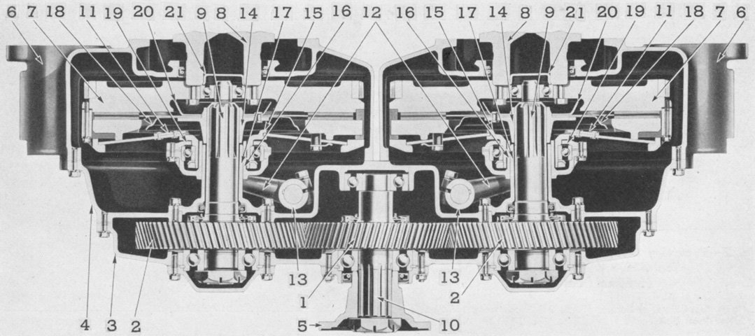
The legend for this cross-sectional view is as follows: 1. Oil cooler adapter. 2. Oil cooler. 3. Blower housing. 4. Blower rotors. 5. Air cleaner. 6. Secondary fuel filter. 7. Camshaft. 8. Rocker arm. 9. Injector. 10. Injector control rack tube lever. 11. Water outlet manifold. 12. Exhaust manifold. 13. Balancer shaft. 14. Valve rocker cover. 15. Push rod. 16. Section of piston and connecting rod. 17. Air box. 18. Solenoid air inlet control. 19. Air inlet housing. 20. Connecting rod bearing shell. 21. Crankshaft. 22. Main bearing shell. 23. Lubricating oil pump assembly. 24. Lubricating oil pump driven gear. 25. Air heater. 26. Air heater fuel pipe. 27. Clutch shift levers. (Picture from TM 9-1750G Ordnance Maintenance--General Motors Twin Diesel 6-71 Power Plant for Medium Tanks M3A3, M3A5, and M4A2.)
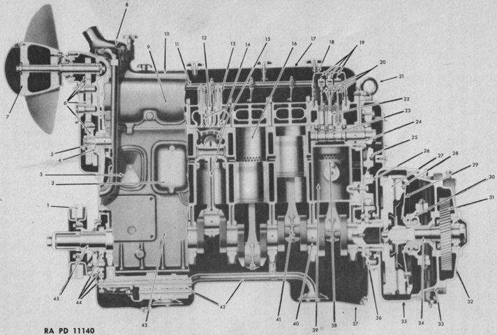
An LC engine is sectionalized in this drawing. 1. Vibration damper. 2. Air heater cover. 3. Handhole cover. 4. Camshaft bearing (Plain) (Thrust on LA). 5. Camshaft. 6. Fan drive gear train. 7. Fan assembly. 8. Thermostat housing. 9. Exhaust manifold. 10. Water outlet manifold. 11. Injector control tube and bracket assembly. 12. Injector assembly. 13. Exhaust valve spring. 14. Exhaust valves. 15. Sectional view of piston and connecting rod assembly. 16. Cylinder liner. 17. Valve rocket cover. 18. Fuel pipe. 19. Exhaust and injector rocket arm assemblies. 20. Push rods. 21. Lifter bracket assembly. 22. Cam follower. 23. Cam. 24. Camshaft bearing (Thrust) (Plain on LA). 25. Camshaft gear. 26. Idler gear. 27. Flywheel. 28. Clutch pressure plate. 29. Clutch spring. 30. Clutch release spring. 31. Engine drive gear. 32. Transfer gear housing. 33. Clutch housing. 34. Engine drive shaft. 35. Flywheel housing. 36. Crankshaft gear. 37. Oil pan. 38. Cylinder air inlet port. 39. Cylinder wall. 40. Main bearing. 41. Connecting rod bearing. 42. Lubricating oil pump assembly. 43. Cylinder block. 44. Lubricating oil pump gear train. 45. Crankshaft. (Picture from TM 9-1750G Ordnance Maintenance--General Motors Twin Diesel 6-71 Power Plant for Medium Tanks M3A3, M3A5, and M4A2.)
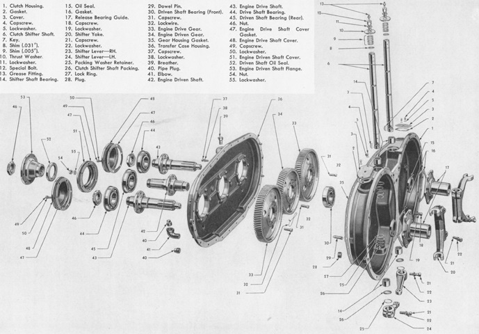
An exploded view of the power transfer unit is shown here. Power was delivered to the transfer unit from each engine via a heavy-duty 16" (41cm) dry disc clutch at each engine flywheel. Each clutch had its own throw-out lever, allowing either one to be manually locked out from the driver's position so that the tank could operate on a single engine if needed. The clutches' driven plates were splined to drive shafts, each with a helical gear that meshed with a single gear on the driven shaft that led to the propeller shaft and transmission. Early engines were built with 80-tooth drive gears and 67-tooth driven gears (1:1.19), while later engines had 85-tooth drive gears and 62-tooth driven gears (1:1.37), which increased the vehicle speed from 25 to 29mph (40 to 47kph) at 2100rpm. (Picture from Model 6046 Series 71 Twin 6 Cylinder Diesel Engine Maintenance Manual.)
The assembled power transfer unit is the subject of this diagram. 1. Driven gear (67 teeth). 2. Drive gear (80 teeth). 3. Transfer case housing. 4. Clutch housing. 5. Engine driven shaft flange. 6. Flywheel housing. 7. Flywheel. 8. Crankshaft. 9. Engine drive shaft. 10. Engine driven shaft. 11. Clutch spring assembly. 12. Shifter yoke. 13. Clutch shifter shaft. 14. Driven disc hub 15. Clutch spring hub. 16. Clutch release bearing sleeve. 17. Clutch release bearing sleeve guide. 18. Rear oil slinger (large). 19. Clutch release bearing sleeve cover. 20. Front oil slinger (small). 21. Grease retainer. (Picture from Model 6046 Series 71 Twin 6 Cylinder Diesel Engine Maintenance Manual.)
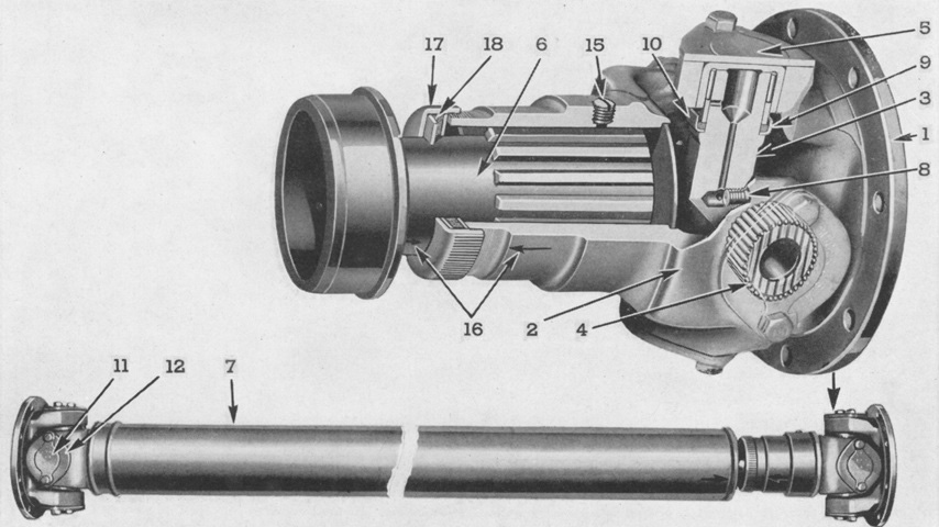
The tubular propeller shaft was a Spicer heavy-duty needle bearing unit. Late-production tanks featured a slightly longer propeller shaft with a diameter increased to 4" (10cm) from 3.5" (8.9cm). 1. Circular flange yoke. 2. Sleeve yoke assembly. 3. Journal cross or trunnion. 4. Needle bearing assembly. 5. Bearing cap. 6. Splined stub shaft. 7. Shaft tube. 8. Relief valve--each end. 9. Gasket. 10. Gasket retainer. 11. Lock strap. 12. Stub ball yoke. 15. Pipe plug--splined joint. 16. Aligning arrows. 17. Dust cap. 18. Cork washer. (Picture from Model 6046 Series 71 Twin 6 Cylinder Diesel Engine Maintenance Manual.)
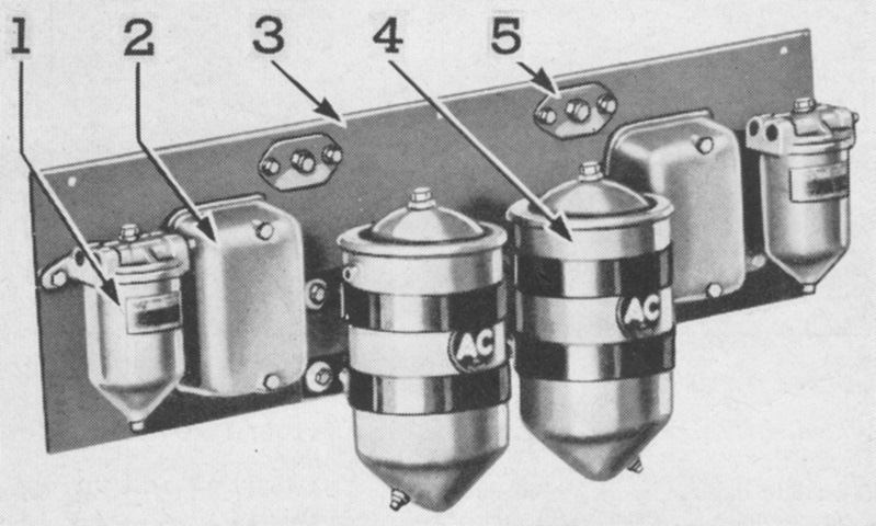
A single Model S-2 (military) replaceable-type lubricating oil filter was used for each engine, and these were mounted on an accessory panel at the front of the engine compartment. The components of the accessory panel were: 1. Primary fuel filter. 2. Heater coil box. 3. Filter panel. 4. Lubricating oil filter. 5. Auxiliary starter switch. (Picture from Model 6046 Series 71 Twin 6 Cylinder Diesel Engine Maintenance Manual.)
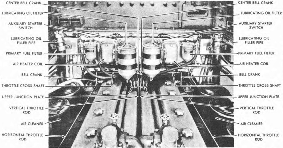
The filter panel can be seen installed in the engine compartment. (Picture from TM 9-753 Medium Tanks M3A3 and M3A5.)
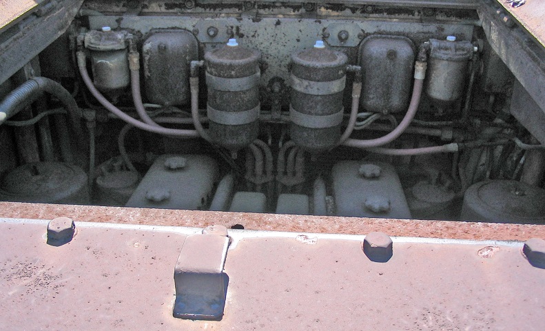
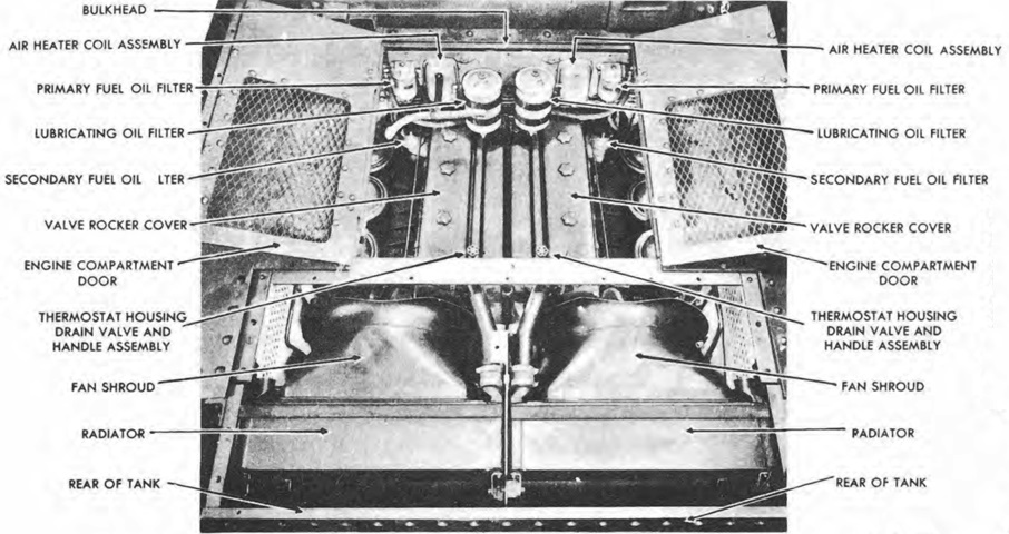
Looking forward into the open engine compartment, the connections for the filters on the accessory panel can be seen on the front wall. The valve rocker covers for the two engines are low in the engine compartment, and between them are the water outlet and exhaust manifolds. Two cylindrical air cleaners are just visible at the lower corners of the opening.
The exhaust system was composed of two exhaust manifolds, two mufflers each with a support bracket, two 90° elbows, and two exhaust pipes. 1. Exhaust manifold. 2. Exhaust gasket. 3. Exhaust elbow. 4. Exhaust pipe. 5. Exhaust muffler support bracket. 6. Exhaust muffler. (Picture from Model 6046 Series 71 Twin 6 Cylinder Diesel Engine Maintenance Manual.)
The engine compartment is shown with the powerplant removed. (Picture from TM 9-753 Medium Tanks M3A3 and M3A5.)
Two vertical and two horizontal fuel oil tanks were installed in the engine compartment. Fuel was used from the tanks on one side at a time; when the tanks on one side emptied, the fuel shut-off valve control lever was used to select the other side's tanks. (Picture from TM 9-753 Medium Tanks M3A3 and M3A5.)
Compared to the sharp-edged hull machines above, the relative lack of rivets due to welding much of this vehicle is obvious. (Picture from TM 9-753 Medium Tanks M3A3 and M3A5.)
The dearth of rivets caused by the use of welding is well illustrated by looking at the side of the tank. This vehicle is a later-production example, as the side door has been welded closed. A closer view of the welded shut side door and pistol port are provided on the right.
Welding the hull did not eliminate all rivets, but their use was drastically reduced.
Although the side doors have been welded shut, the tank retains apertures for both hull machine guns. As seen on the right, one of the apertures has been blanked off internally.
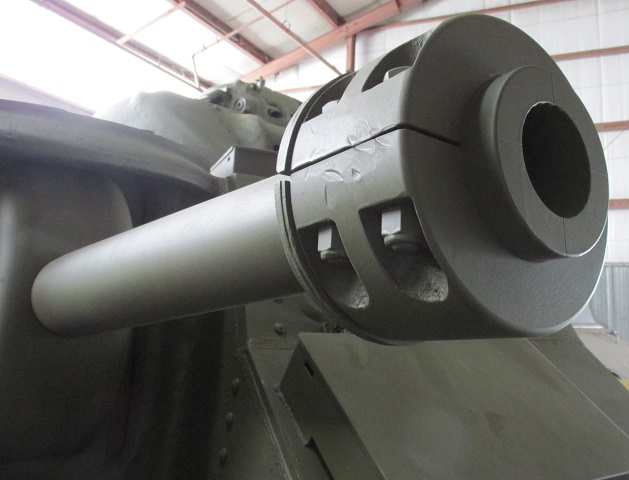
Details of the counterweight on the 75mm gun M2 are provided here.
The traverse available to the 75mm gun's sighting periscope can be gleaned from this angle. A stowage box is on the far side of the periscope, and the hull roof hatch and hull roof ventilator are on the left side of the image. The pistol port in the hull side is open.
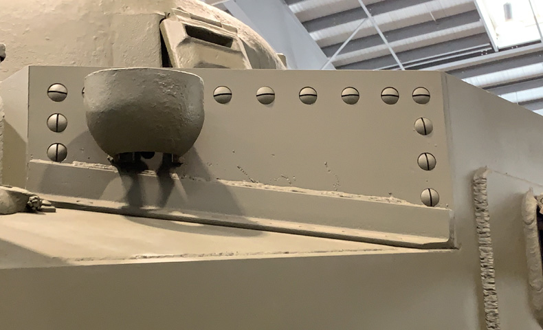
The upper rear plate behind the 75mm gun was still attached with screws on this machine, but the angle frame at the bottom was welded to the plate instead of riveted.
The second hull ventilator was installed in the roof's front left corner. As seen in the detail on the right, the counterweight for the 37mm gun is not present on this tank, although its aperture remains unplugged.
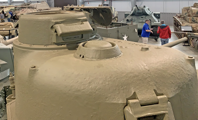
The ventilator on the turret roof was adjacent to the cupola, which is open.
The hinged cupola hatch opened to the front, and two rests were bolted to the upper corners of the cupola's front face. With the shield raised, the cupola vision slit can be seen in the right image.
This interior view shows the padding above the viewing slits and protectoscope, the machine gun cradle, and a control lever for the far viewing slit shield. Also note the hole in the cupola door for signaling.
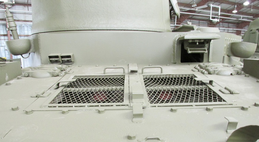
The rear deck featured twin armored air intake louvres protected by mesh screens. Filler cap covers can be seen on the rear deck and in front of the sponson stowage boxes.
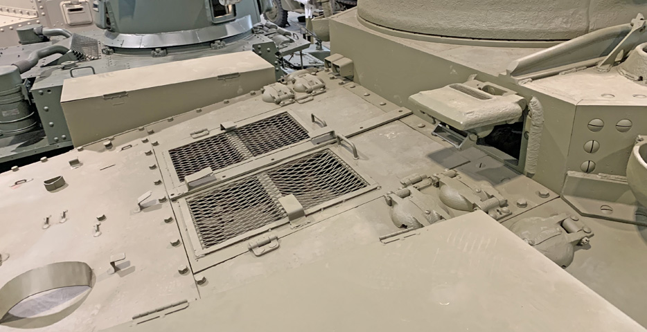
The engine deck is seen from a higher vantage point. The front filler caps in the bolted removable plate were for lubricating oil, and the fillers directly behind these were for cooling water. Fuel oil was replenished by the outboard caps that were not part of the removable plate.
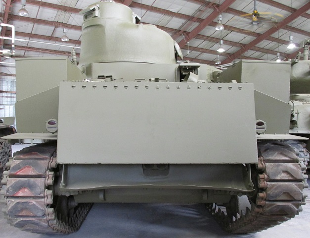
The rear armor was extended downward compared to radial-engine tanks, and the rear engine access doors were necessarily deleted.
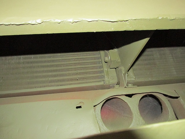
The mufflers for the engines met in the center of the rear of the vehicle, and a deflector was mounted to keep the exhaust gases from stirring up too much dust. The solid lower rear hull can be contrasted with the radial-engined tank above. The reason for the changes to the upper rear armor was that the radiators for the GM 6046 were mounted at the rear above the mufflers as seen on the right, a concern that tanks powered by the air-cooled radials did not have.
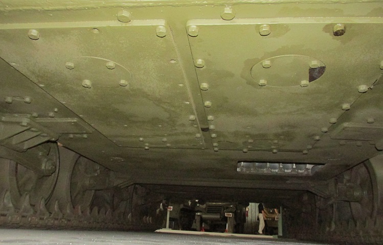
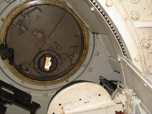
The left picture is looking forward from the rear of the tank. The long rectangular engine inspection plates can be seen in the foreground, each with a round cover for engine oil drain plug access. Since this tank has no side hull doors, it was equipped with a floor escape hatch, the opening for which which can be seen in front of the right-hand engine inspection plate. In the right picture, looking straight up into the escape hatch opening, the front of the tank is to the right of the image. The transfer case can be seen to the left, and the propeller shaft runs off to the right to engage the transmission. Control linkages are near the bottom of the image, and a 75mm ammunition rack can be seen to the right. The underneath of the turret basket is directly overhead.
The large Chrysler multibank engine installed in M3A4 necessitated a longer hull to fit in the tank. The distance between the bogies was also therefore increased, and the rear deck roof and engine compartment floor had bulges to accommodate the A57 engine. (Picture from Development of Armored Vehicles, volume 1: Tanks and Modern Ordnance Materiel.)
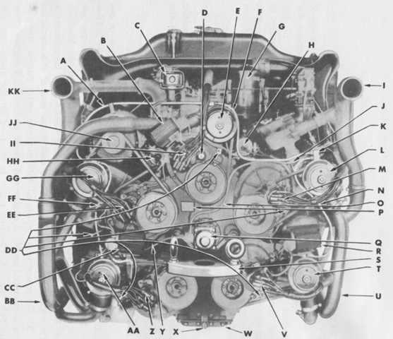
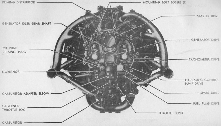
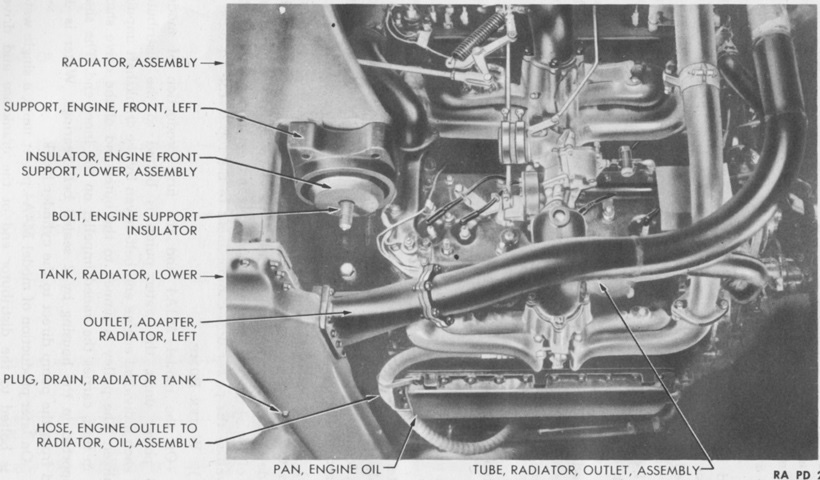
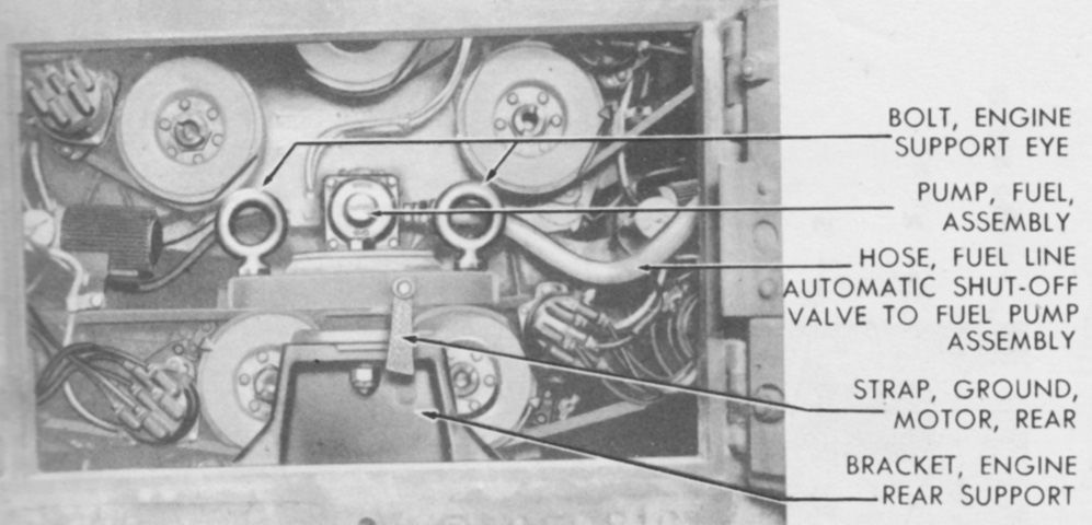
The distributor end of the A57 is shown here. A. Tube, water pump air relief (engine no. 1 to no. 2). B. Coil, ignition, assembly (no. 1 engine). C. Cleaner, air, crankcase ventilator, assembly. D. Shaft, drive, tachometer. E. Pump, water, assembly (no. 1 to no. 5 engine). F. Tube, water pump air relief (no. 1 engine). G. Filter, oil (absorption type). H. Coil, ignition (no. 5 engine). I. Pipe, exhaust (nos. 4 and 5 engines). J. Tube, fuel pump to branch connection, assembly (for nos. 4 and 5 carburetors). K. Connection, water pump air relief tube. L. Pump, water, assembly (no. 5 engine). M. Distributor, ignition, assembly (no. 5 engine). N. Tube, water pump air relief (no. 4 to no. 5 engine). O. Tube, fuel pump to no. 1 carburetor, assembly. P. Plate, serial number, engine. Q. Pump, fuel, assembly. R. Coil, ignition, assembly (no. 4 engine). S. Support, engine, rear. T. Pump, water, assembly (no. 4 engine). U. Tube, radiator outlet, assembly (nos. 4 and 5 engines). V. Distributor, ignition, assembly (no. 4 engine). W. Pan, oil. X. Plug, drain, oil pan. Y. Tube, fuel pump to branch connection, assembly (for nos. 2 and 3 carburetors). Z. Distributor, ignition, assembly (no. 3 engine). AA. Pump, water, assembly (no. 3 engine). BB. Tube, radiator outlet, assembly (nos. 2 and 3 engines). CC. Coil, ignition, assembly (no. 3 engine). DD. Cock, drain, cylinder water jacket, assembly. EE. Distributor, ignition, assembly (no. 2 engine). FF. Tube, water pump air relief (no. 2 to no. 3 engine). GG. Pump, water, assembly (no. 2 engine). HH. Coil, ignition, assembly (no. 2 engine). II. Distributor, ignition, assembly (no. 1 engine). JJ. Generator, assembly. KK. Pipe, exhaust (nos. 1, 2, and 3 engines). (Picture from TM 9-1750F Ordnance Maintenance--Power Unit for Medium Tanks M3A4 and M4A4.)
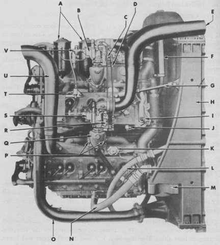
The power unit's left side is labeled in this picture. Bore and stroke were 3.4375" (8.7312cm) and 4.5" (11cm), respectively, for a displacement of 1,253.0in³ (20.533L). The compression ratio was 6.2:1, and weight with accessories was 5,375lb (2,438kg). (Picture from TM 9-1750F Ordnance Maintenance--Power Unit for Medium Tanks M3A4 and M4A4.)
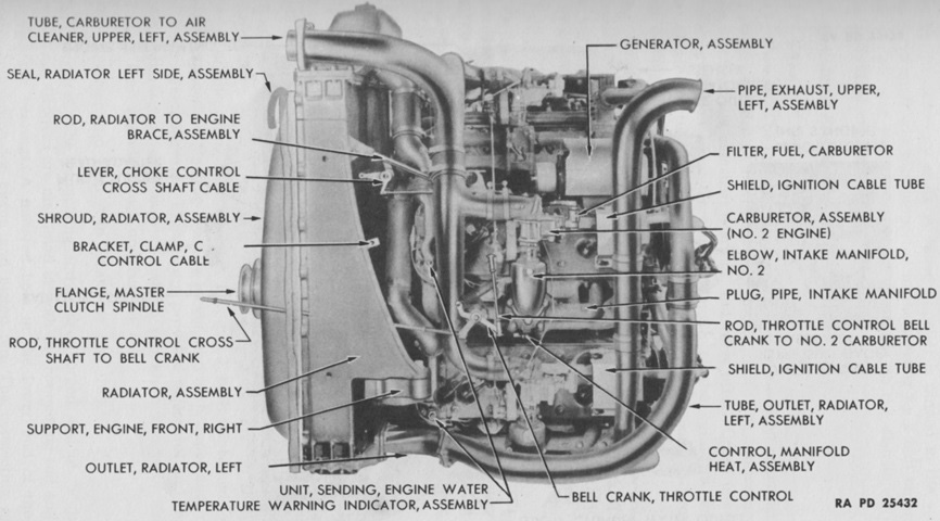
The right side is shown here. A. Filter, oil, w/clamp, assembly. B. Carburetor, assembly (no. 5 engine). C. Rod, choke, assembly (no. 5 to no. 4 carburetor). D. Rod, throttle control, assembly (from no. 4 to no. 5 carburetor). E. Tube, carburetor to air cleaner, upper, right, assembly. F. Hose, crankcase vent air cleaner outlet pipe. G. Rod, brace, radiator to engine assembly. H. Radiator assembly. I. Unit, sending, engine water temperature gage, assembly. J. Unit, sending, engine water temperature warning indicator, assembly. K. Unit, sending, exhaust stack temperature warning indicator, assembly. L. Hose, engine to oil cooler (engine end). M. Support, engine, front, right. N. Hose, oil tank to engine (engine end). O. Tube, radiator outlet, assembly. P. Stud, attaching, carburetor adapter elbow. Q. Elbow, adapter, carburetor. R. Governor, carburetor, assembly. S. Carburetor, assembly (no. 4 engine). T. Connection, branch, fuel pump to nos. 4 and 5 carburetor tube. U. Pipe, exhaust, upper, right, assembly. V. Filter, fuel, carburetor, assembly. (Picture from TM 9-1750F Ordnance Maintenance--Power Unit for Medium Tanks M3A4 and M4A4.)
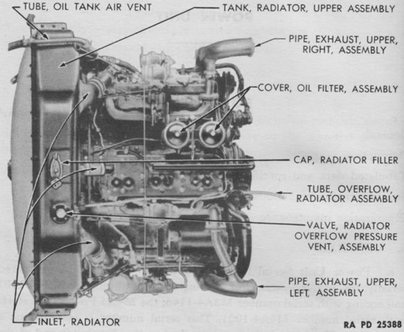
The top of the power unit can be seen in this picture. Overall length, width, and height were 54.125" (137.48cm), 58.75" (149.2cm), and 56.5" (144cm), respectively. (Picture from TM 9-1750F Ordnance Maintenance--Power Unit for Medium Tanks M3A4 and M4A4.)
The power unit is shown here from the bottom left. (Picture from TM 9-1750F Ordnance Maintenance--Power Unit for Medium Tanks M3A4 and M4A4.)
Two outward-opening doors could be found in the lower rear hull for engine access, and the power unit is viewed through this opening. (Picture from TM 9-1750F Ordnance Maintenance--Power Unit for Medium Tanks M3A4 and M4A4.)
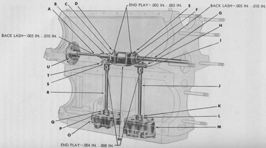
The five engines were assembled to a one-piece cast-iron crankcase, with oil passages cast and drilled into it. An oil pan and a sump were attached to the bottom. In this sketch, the accessory drive shaft, fuel pump drive assembly, and oil pumps are shown in position in the crankcase. A. Shaft, drive, fuel pump. B. Sleeve, accessory drive shaft. C. Washer, thrust, accessory drive shaft gear. D. Gear, accessory drive shaft. E. Gear, accessory drive shaft. F. Washer, thrust, accessory drive shaft gear. G. Shaft, drive, accessory. H. Gear, oil scavenger pump drive shaft. I. Washer, thrust, oil scavenger pump drive shaft gear. J. Shaft, drive, oil scavenger pump. K. Washer, thrust, oil scavenger pump drive shaft. L. Washer, oil scavenger pump drive shaft. M. Pump, scavenger, oil, assembly. N. Support, accessory drive shaft. O. Pump, pressure, oil, assembly. P. Washer, oil pressure pump drive shaft. Q. Washer, thrust, oil pressure pump drive shaft. R. Shaft, drive, oil pressure pump. S. Washer, thrust, oil pressure pump drive shaft gear. T. Gear, oil pressure pump drive shaft. U. Drive, fuel pump, assembly. (Picture from TM 9-1750F Ordnance Maintenance--Power Unit for Medium Tanks M3A4 and M4A4.)
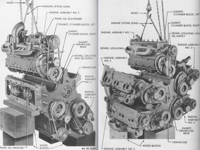
On the left, engines nos. 4 and 5 are shown assembled to the crankcase, with engine no.3 being lowered into position. With the oil pan yet to be attached, the oil pumps at the bottom of the crankcase are visible. On the right, engine no.1 is completing the assembly, and the orientation of the bottom engines can be seen. (Picture from TM 9-1750F Ordnance Maintenance--Power Unit for Medium Tanks M3A4 and M4A4.)
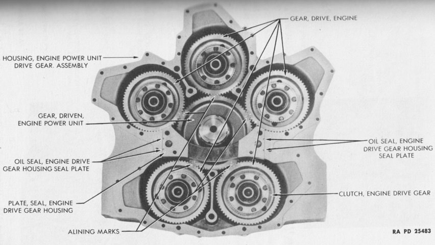
An interior view of the power unit drive gear housing is provided here. Each engine drive gear was bolted to the end of its engine's crankshaft, and these five drive gears drove the engine power unit driven gear, which was keyed to the power unit driven gear shaft, which drove the engine clutch. (Picture from TM 9-1750F Ordnance Maintenance--Power Unit for Medium Tanks M3A4 and M4A4.)
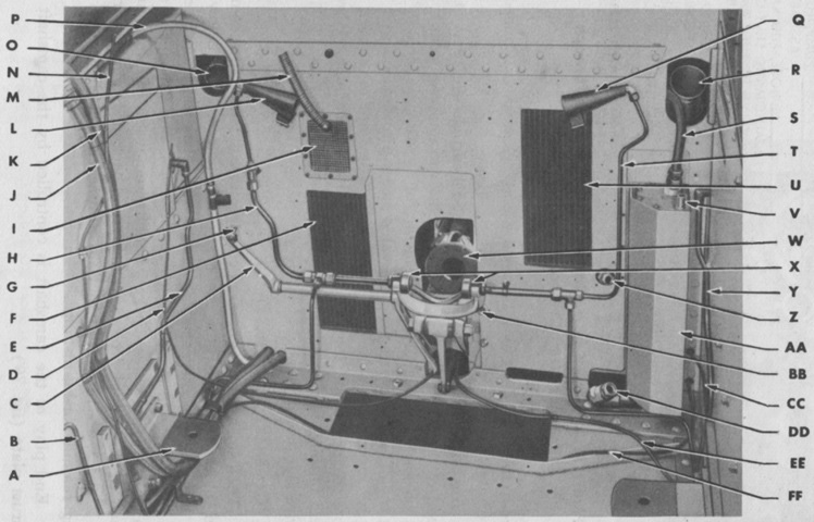
The empty power unit compartment is shown in this picture. A. Bracket, engine front support, left. B. Tube, fire extinguisher floor elbow to left floor tee, assembly. C. Bracket, throttle control cross shaft, left, assembly. D. Cable, choke control, assembly. E. Tube, outlet, fuel tank, left, front, assembly. F. Cooler, oil, transmission, assembly. G. Screw, stop, throttle control cross shaft. H. Tube, fire extinguisher bulkhead tee to left front tee, assembly. I. Screen, auxiliary generator exhaust. J. Cable and conduit, battery box to engine harness connector, assembly. K. Cable and conduit, starter and generator, assembly. L. Nozzle, fire extinguisher tube, left, front. M. Tube, auxiliary generator muffler outlet, w/elbow, assembly. N. Conduit, ignition coil mainfeed cable. O. Opening, carburetor air cleaner. P. Conduit, fuel gage, tail and stop light cables. Q. Nozzle, fire extinguisher tube, right, front. R. Opening, carburetor air cleaner. S. Tube, engine oil cooler to oil air remover tube, assembly. T. Tube, fire extinguisher right front tee to nozzle, assembly. U. Cooler, oil, engine, assembly. V. Tube, hose, oil tank to air vent tube. W. Yoke, rear propeller shaft universal joint flange, rear. X. Bearing, throwout, clutch. Y. Tube, outlet, fuel tank, right, front, assembly. Z. Connector, oil cooler to radiator oil hose. AA. Hopper, oil tank assembly. BB. Yoke, clutch release lever. CC. Wire, control, fuel line shut-off valve, right, assembly. DD. Connection, oil tank to radiator oil hose. EE. Cable, tachometer, assembly. FF. Wire, control, fuel line shut-off valve, left, assembly. (Picture from TM 9-1750F Ordnance Maintenance--Power Unit for Medium Tanks M3A4 and M4A4.)
