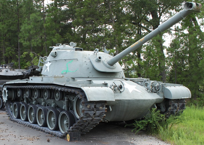
90mm Gun Tank M48 Patton 48.
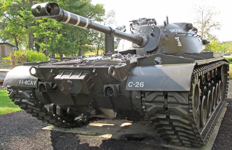
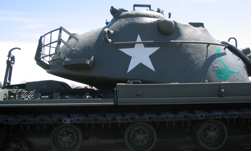
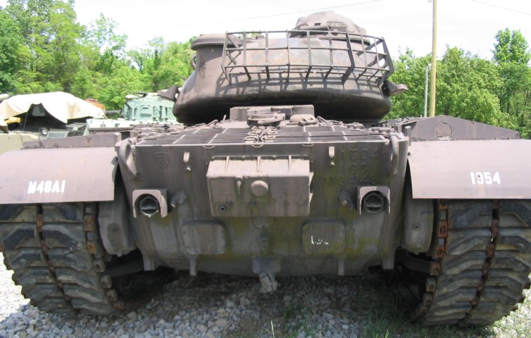
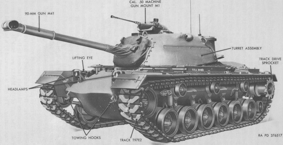
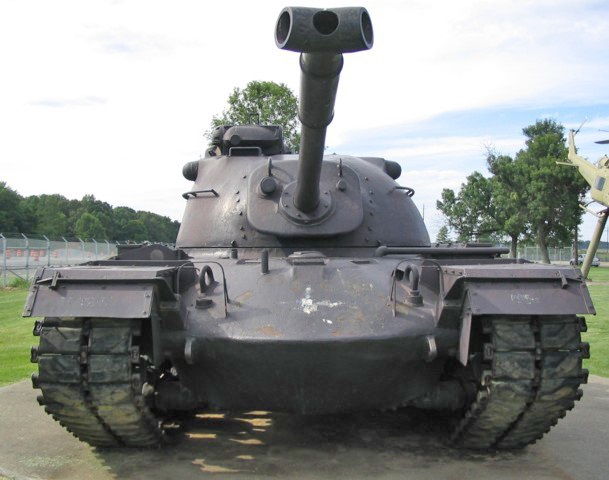
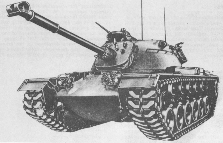
The elliptical shape of the hull and turret castings are easily seen in this frontal view. This tank is fitted with a T-shaped muzzle brake. The right-hand aperture for the stereoscopic rangefinder is visible on the turret side below the commander's cupola, and the gunner's telescope T156E1 would peer through the hole in the gun shield. (Picture courtesy Calvin.)
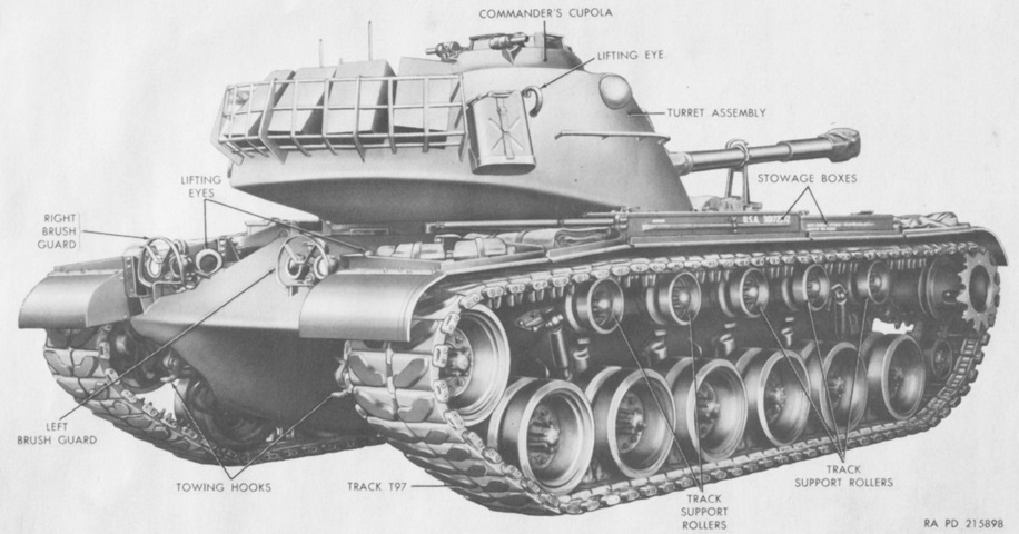
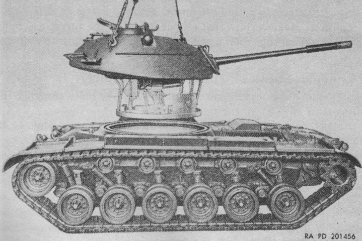
The turret is reversed, and the gun is secured in its travel lock. (Picture from TM 9-7012 90-mm Gun Tank M48.)
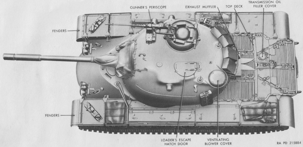
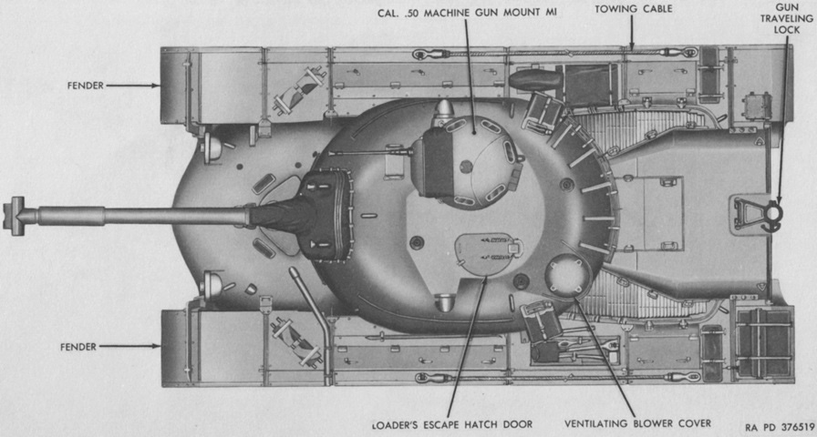
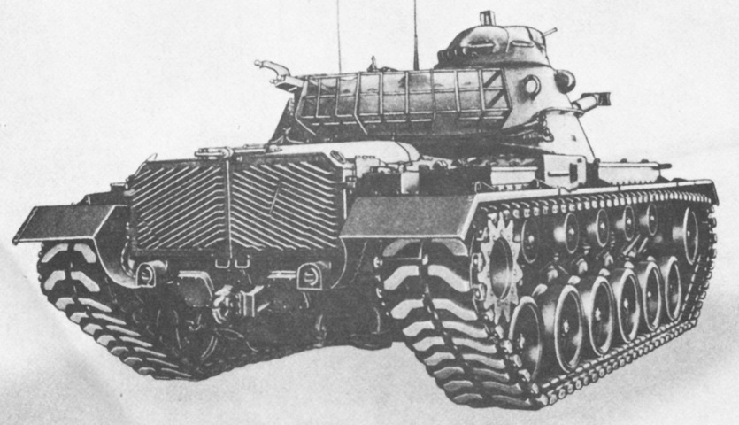
The armor contours, including the prominent "ears" on the turret for the rangefinder, can be seen in this top-down view. The M48 and M48A1 had their exhausts routed through the top deck, and deflectors were necessary to keep the hot exhaust gases from heating the gun travel lock, a situation which would eventually cause it to bind. (Picture from TM 9-7012 90-mm Gun Tank M48.)
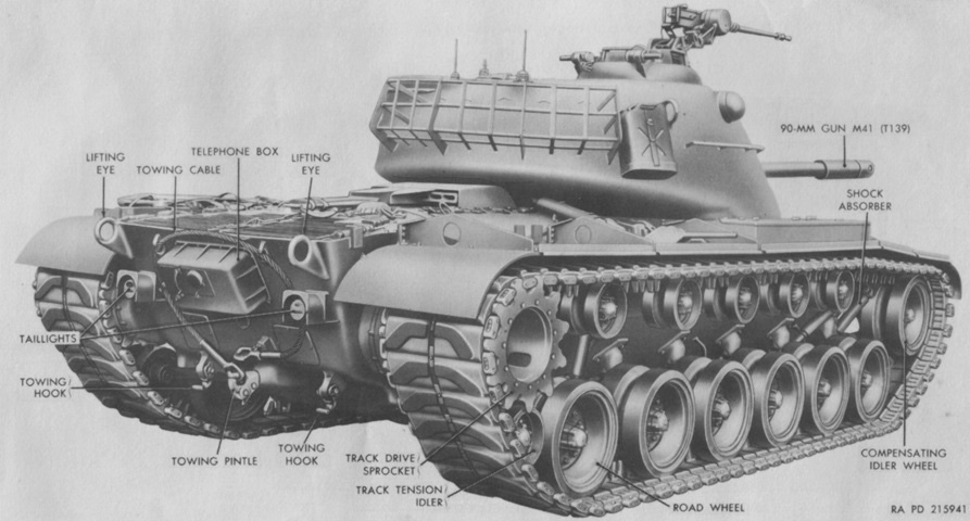
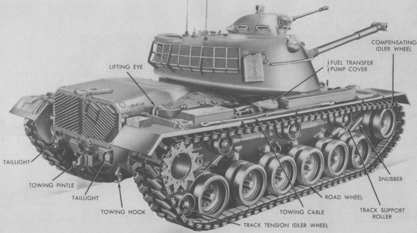
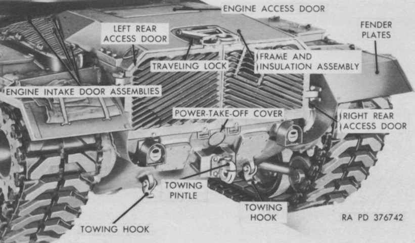
The rear of the tank is detailed in this picture. (Picture from TM 9-7012 90-mm Gun Tank M48.)
The large box in the middle of the hull rear plate housed an infantry phone. The square plates below and outboard of the phone box and the central circular plate just below the phone box were all for access to the transmission. Note that this tank has had its track tensioning idlers removed from behind the rear road wheels.
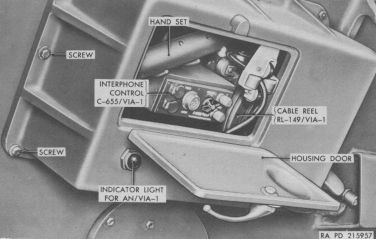
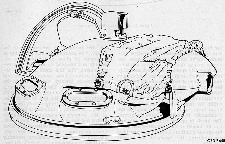
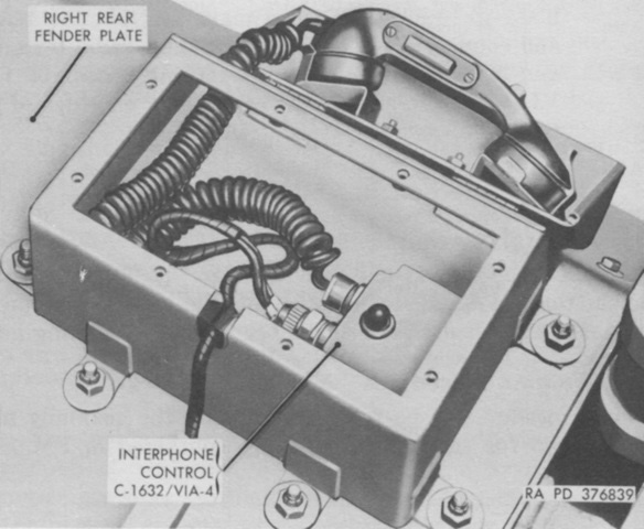
The box containing the auxiliary interphone equipment AN/VIA-1 has been opened, showing the location of the hand set and interphone control box. The hand set was connected to a 40' (12m) cable on a take-up reel which allowed infantry to communicate with the tank. A control box C-664/VIA-1 was mounted on the turret interior wall near the loader, and this was equipped with a light that flashed when the hand set switch was pressed. Similarly, the loader's control box had a switch that flashed the indicator light on the external box on the tank rear so that the loader could also signal following troops. The control box C-655/VIA-1 featured volume control knobs, jacks for an auxiliary hand set or head set and microphone, and telephone binding jacks. (Picture from TM 9-7012 90-mm Gun Tank M48.)
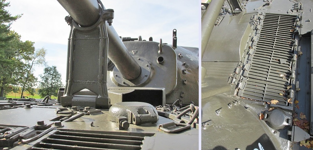
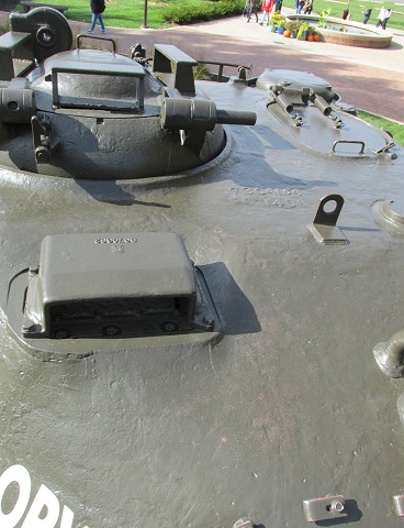
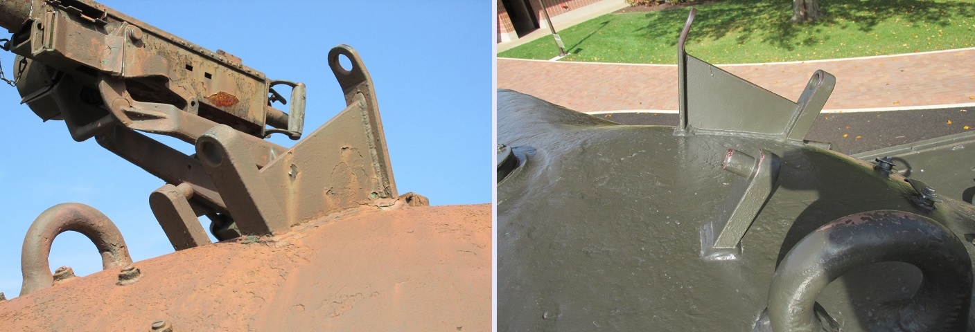
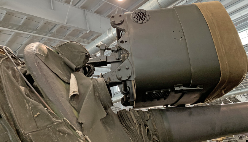
The proximity of the travel lock to the engine exhaust is well illustrated in these views, as well as the potential effectiveness of the deflectors. The armored cover in the foreground of the left image protected the engine oil filler. In the right image, a fuel filler cover is visible in the lower right; another filler was on the opposite side of the hull.
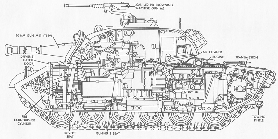
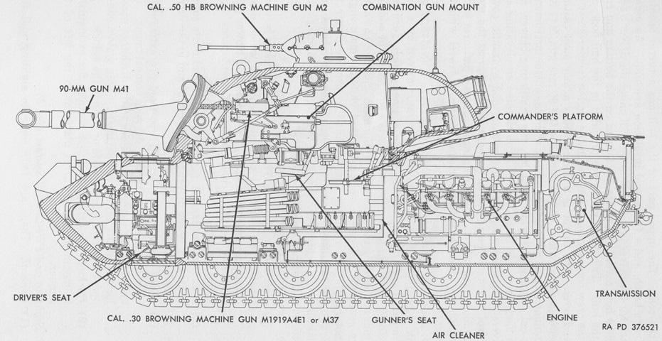
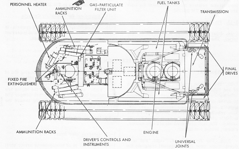
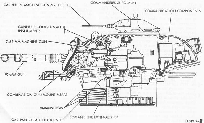
The interior arrangement of the tank can be seen in this sketch. The coaxial machine gun seen in this early vehicle is a .50 caliber weapon; T48 pilots were armed with a .50 caliber machine gun on the left of the gun mount and a .30 caliber machine gun on the right of the gun mount. (Picture from TM 9-7012 90-mm Gun Tank M48.)
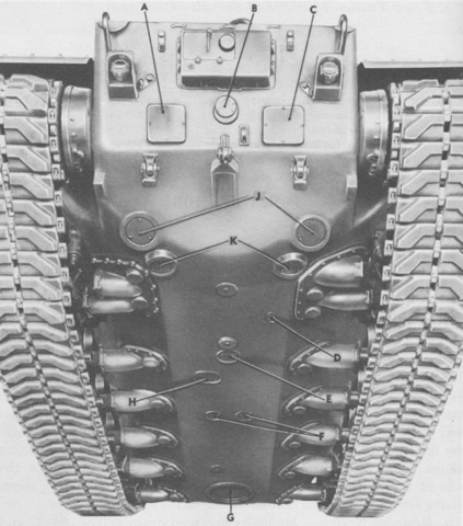
The hull was cast with a welded armor plate floor, and the various covers and ports in the hull underside are labeled here. Note the mounting point for the track tension idler near the rear road wheel. A. Transmission left access plate. B. Transmission center access plate. C. Transmission right access plate. D. Auxiliary engine drain hole cover. E. Main engine drain hole cover. F. Fuel tank drain hole covers. G. Driver's escape hatch door. H. Main engine oil filter access hole cover. J. Brake rod access plates. K. Transmission drain hole covers. (Picture from TM 9-7012 90-mm Gun Tank M48.)
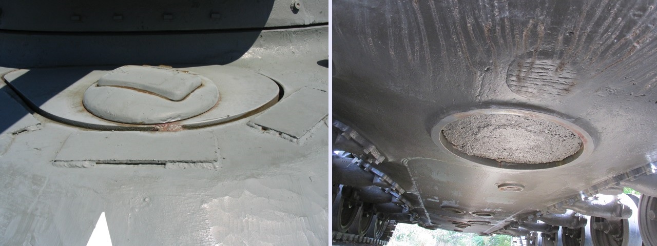
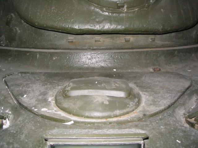
As seen on the left, the drivers of M48s had a small hatch compared with later versions of the tank. This vehicle had been equipped with an infrared periscope for the driver, which was mounted in the hatch door. The driver was also provided with an escape hatch in the hull floor below his seat, the opening for which is shown on the right.
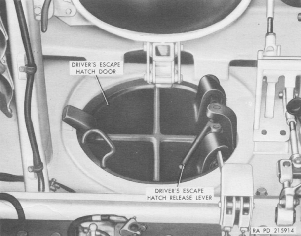
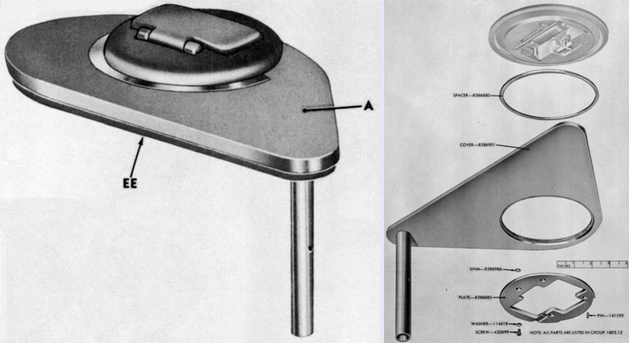
The driver's escape hatch is shown here from the interior of the tank. If the lever was located on the right, it was pushed forward to release the hatch door; if the lever was on the left it was pulled back. The driver's seat, visible at the top of the image with its seatback removed, needed to be in the dumped position in order to open the escape hatch door. (Picture from TM 9-7012 90-mm Gun Tank M48.)
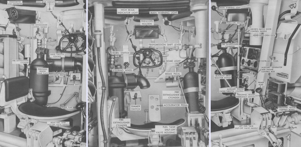
The left, center, and right portions of the driver's position are labeled on the left, center, and right, respectively. With the deletion of the assistant driver and bow machine gun, the driver sat centrally in the hull, and a more conventional steering wheel replaced the steering levers or wobble stick found in earlier designs. The backrest has been removed from the driver's seat for clarity. This is a late-production hull with the larger driver's hatch and no linkages between the hatch and periscopes; this tank would eventually have its Chrysler machine gun cupola replaced by the cupola M1 and be redesignated as an M48A1. Another change that occurred during production was the reorientation of the driver's heater outlet so that it wasn't blowing directly on him, which caused issues with hyperthermia. (Picture from TM 9-7012 90-mm Gun Tank M48.)
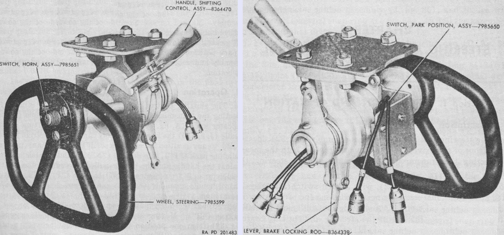
Front and rear views of the new steering wheel are provided. (Picture from TM 9-7013-1.)
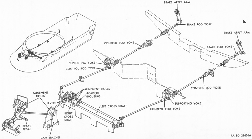
The brake linkages are diagrammed here. The connections were mechanical, and the linkage connected to an equalizing mechanism behind the driver before proceeding to the transmission. (Picture from TM 9-7012 90-mm Gun Full Tracked Combat Tanks M48, M48A1, and M48C.)
A direct comparison can be made of the shapes of the small (left) and large (right) driver's hatches. Note that the large hatch still opened and rotated to the right, contrary to its appearance in the image. (Picture from ORD 9 SNL G-254 Tank, 90-mm Gun, M48 (T48), M48A1, and M48C.)
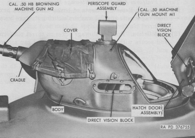
The commander of the M48 was provided with a low Chrysler-designed cupola and an external mount for his .50cal machine gun. This was replaced in production with Aircraft Armaments's M1 cupola.
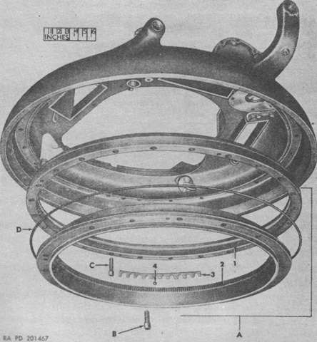
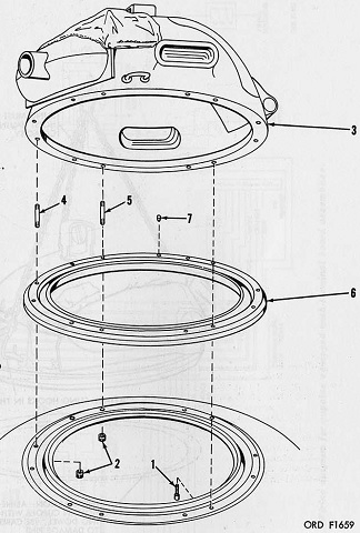
A partially exploded view of the cupola race is provided here. The inner race was secured to the turret by twelve ¾-16NF-3 x 1¼ screws, while the outer race was secured to the cupola body by twenty-four ½-20NF-3 x 1¾ screws. A. Race, commander's cupola, assy. 1. Race, outer. 2. Race, inner. 3. Retainer, ball. 4. Ball, bearing. B. Screw, ¾-16NF-3 x 1¼. C. Screw, ½-20NF-3 x 1¾. D. Seal, cupola race. (Picture from TM 9-7013-1.)
The turret roof is shown here, with the commander's cupola on the left facing away from the camera. The loader's hatch is beside the commander's cupola.
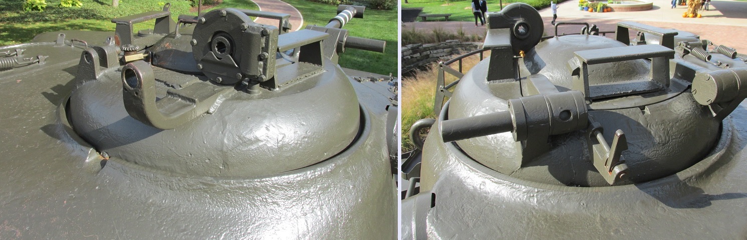
The cupola is shown here from the front and rear in the left and right images, respectively. The commander was provided with four periscopes in the cupola, including one in the hatch door. The cupola provided the commander the capability to aim and fire--but not reload--the .50cal machine gun from under armor; the front view of the cupola provides details of the gearing used to aim the machine gun. Note that the door catch is welded to the periscope guard.
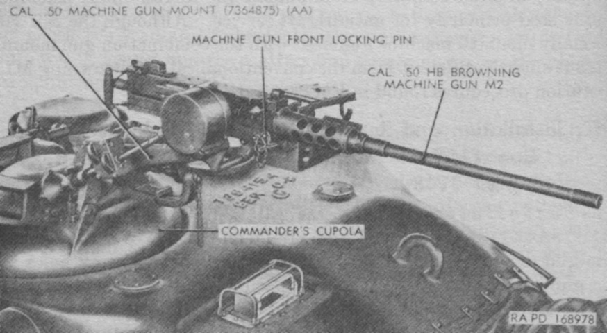
The machine gun is shown here mounted. (Picture from TM 9-7012 90-mm Gun Tank M48.)
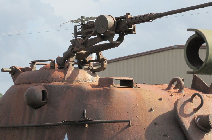
More details of the cupola mount for the .50cal machine gun can be seen here. If necessary to reload the machine gun from under armor, the commander could unlock the mount from the cupola and then crank it to the left so that the loader could gain access to the ammunition box. The mount was then cranked back into position and secured from inside the cupola. The guard for the gunner's M20-series periscope is in front of the commander's cupola.
When not in use, the machine gun mount could be stowed on a bracket welded to the turret roof in front of the loader.
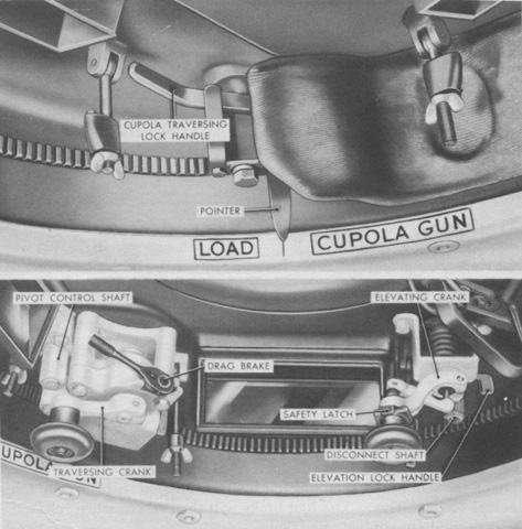
These two images are of the cupola interior. The top image highlights the pointer and reference mark used to align the cupola in the proper position to reload the machine gun from the loader's hatch. Seen in the bottom image is the crank on the disconnect shaft, which was turned counterclockwise to unlock the machine gun, and the the pivot control shaft, which was turned counterclockwise to swing the machine gun over toward the loader. (Picture from TM 9-7012 90-mm Gun Tank M48.)
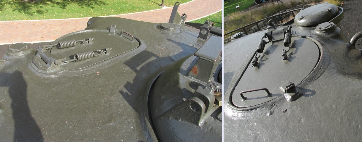
The loader's hatch is highlighted here. As seen on the right, a ventilator was mounted in the turret to the loader's left rear. Antenna mounts can also be seen in front of the ventilator and at the turret rear.
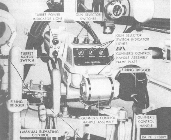
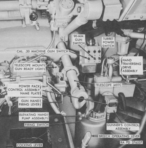
The gunner's controls are shown here. Power traverse and elevation were accomplished by the single control handle: twisting it to the right or left traversed the turret, and the handle was rotated on the axis perpendicular to the gun to elevate the ordnance. The top of the handle was pushed forward to depress the gun, or pulled toward the gunner to elevate the gun. The Seren Tool Company manual traverse handle is out of view to the right of the image. A maximum of 8½in-lb (0.96Nm) was required to traverse the turret with the hand drive. (Picture from TM 9-7012 90-mm Gun Tank M48.)
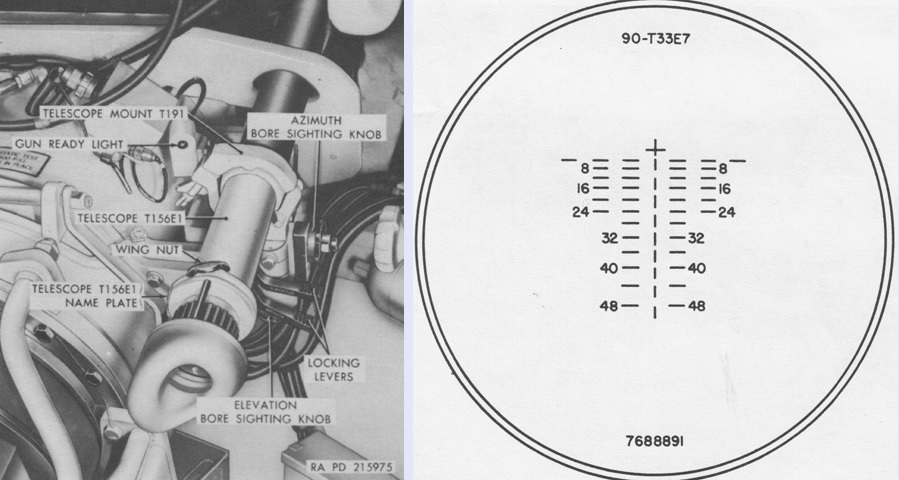
The 8x magnification telescope T156E1 provided the gunner with a secondary direct fire sight if the primary sighting system involving his periscope became inoperable. It was mounted coaxially with the 90mm gun on the right side of the recoil cylinder and had a 7°24' field of view. The vertical range lines and spaces each represented 200 yards (180m), while the horizontal lines and spaces were each 5 mils or 1 lead. The boresight cross represented zero range or deflection. (Picture from TM 9-7012 90-mm Gun Tank M48.)
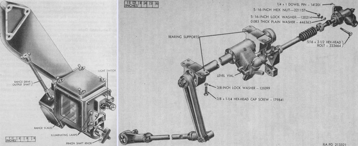
Seen on the left, the range drive T25 found in the phase I through III fire control systems was mounted to the turret roof, and consisted of five range scales and a manually-operated turning mechanism. The bottom four scales represented four different ammunition types and were graduated in yards, while the top scale was graduated in mils and indicated the elevation required for the particular range shown on the ammunition scales. The pinion shaft knob turned both the range scales to the proper range, as well as the output shaft, which transmitted the appropriate superelevation. The unit was 11½" (29.2cm) long and wide, 8" (20cm) tall, and weighed 13½lb (6.12kg). The ballistic drive T24 on the right connected the periscope sights and the range drive. The ballistic unit on the T24 lacked range scales since these were contained in the T25. The T24 was 38" (97cm) long, 11" (28cm) wide, 12" (30cm) high, and weighed 74lb (36kg). (Picture from TM 9-6013 Range Drive T25 and TM 9-6065 Ordnance Maintenance Ballistic Drives M3 (T23E1), M4 (T23), T23E2 and T24.)
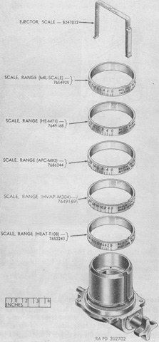
The range drive T25's ammunition and elevation scales are seen here being removed from the base assembly. From top to bottom, the mils scale was graduated from 0 to 63 mils in 1-mil intervals; the M71 high-explosive shell scale read from 0 to 5,000 yards (0 to 4,570m) in 200-yard (180m) intervals; the M82 armor-piercing, capped, shot scale was the same as the M71's; the M304 HVAP shot scale read from 0 to 3,400 yards (0 to 3,110m) in 200-yard (180m) intervals; and the T108 HEAT shell scale read from 0 to 4,400 yards (0 to 4,020m) in 200-yard (180m) intervals. (Picture from TM 9-6013 Range Drive T25.)
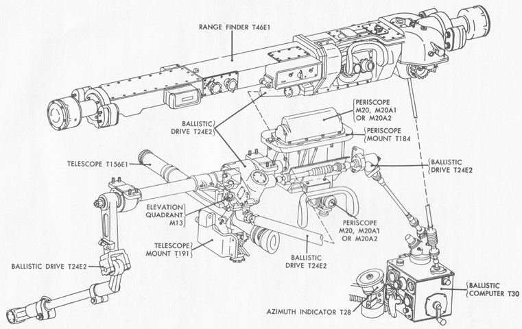
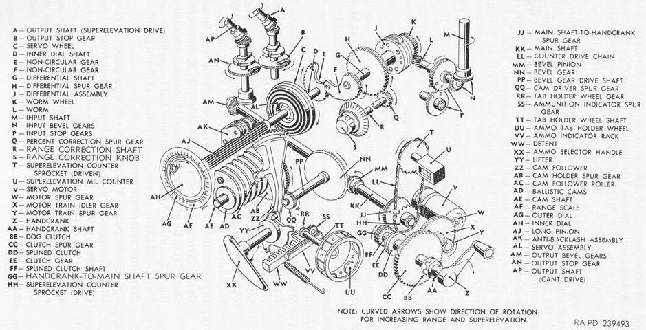
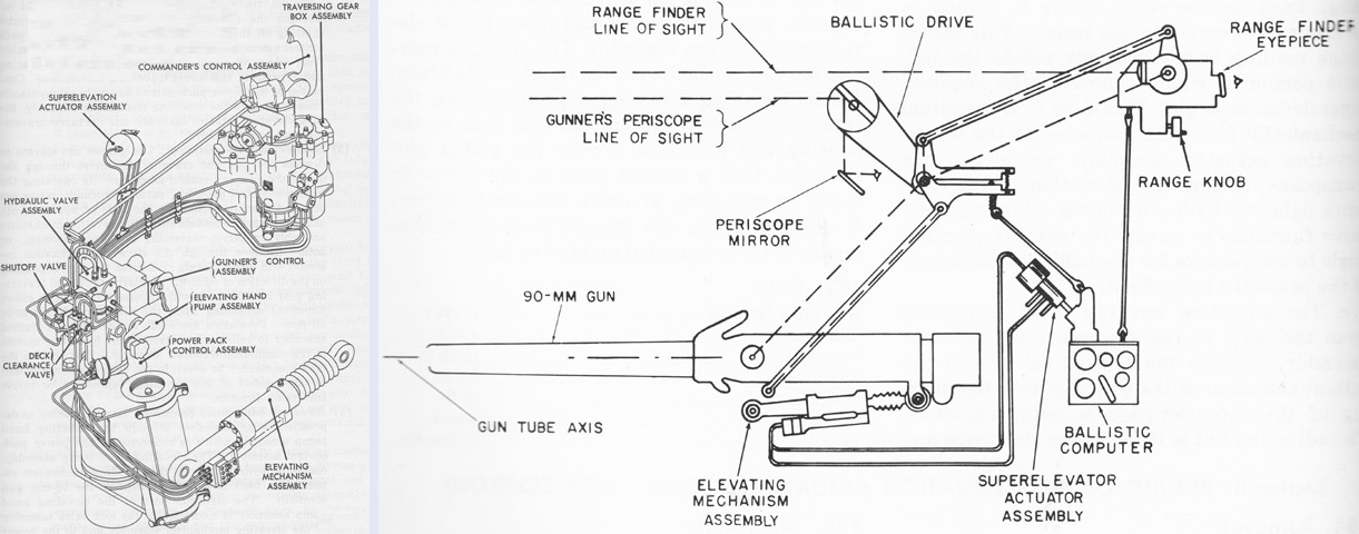
Diagrammed in this sketch is the final, or phase IV, sighting and fire control system. (Picture from TM 9-7012 90-mm Gun Tank M48.)
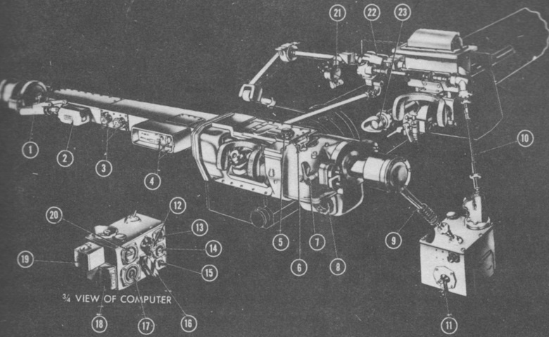
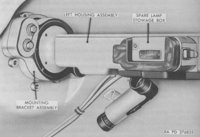
Another view of the fire control system is shown here. 1. Equilibrator. 2. Spare lamp box. 3. Elevation and azimuth boresight knobs. 4. Light switches and brightness control. 5. ICS knob. 6. Range scale. 7. Filter lever. 8. Range knob. 9. Range input shaft. 10. Superelevation output shaft. 11. Manual range crank. 12. Ballistic correction knob. 13. Superelevation scale. 14. Ammunition selection scale. 15. Reset switch. 16. Ammunition selection handle. 17. Ammunition cam access cover. 18. Circuit breaker. 19. Spare cam box. 20. Range dial. 21. Elevation Quadrant, M12. 22. Ballistic Drive, T24E2. 23. Telescope, T156E1. (Picture from FM 17-79 Tank, 90-mm Gun, M48.)
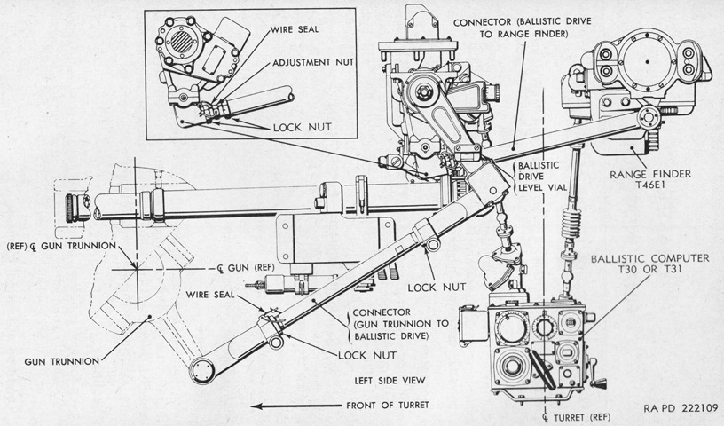
The fire control system is diagrammed from the side in this drawing, which highlights the rangefinder's connections to other devices. (Picture from TM 9-6023 Ordnance Maintenance Range Finder T46E1.)
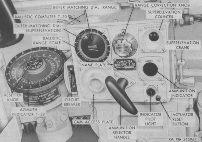
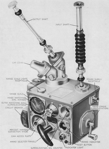
The ballistic computer T30 was an electromechanical device that took range data from the rangefinder T46E1, applied this to ammunition and ballistic corrections entered manually by the gunner, and produced the correct superelevation for the 90mm gun, which was adjusted into the gunner's periscope and rangefinder by the ballistic drive T24E2. The gunner then was able to put the aiming cross onto the target with the correct superelevation applied. The superelevation crank allowed manual introduction of superelevation to the rangefinder and periscope M20. The ammunition selector handle allowed the ballistic cams for different ammunition types to be selected. The range correction knob was graduated to ±15% in 1% intervals. The percentage of correction was based on range as listed on the ballistic range scale. When the circuit breaker switch was in the on position, pressing the actuator reset button placed the computer in electrical operation mode. (Picture from TM 9-7012 90-mm Gun Tank M48.)
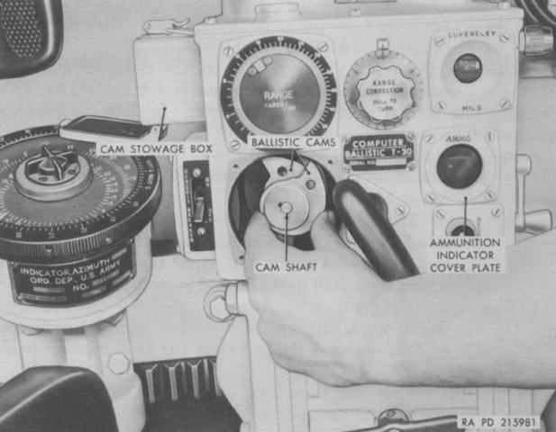
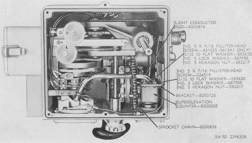
The ballistic cams can be seen here with the cam access plate removed. (Picture from TM 9-7012 90-mm Gun Tank M48.)
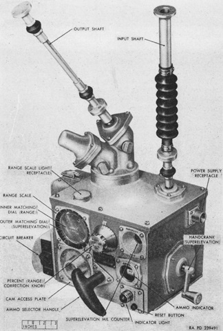
The later ballistic computer T31 is shown here with the input and output shafts visible. (Picture from TM 9-6159 Field and Depot Maintenance Ballistic Computer T31.)
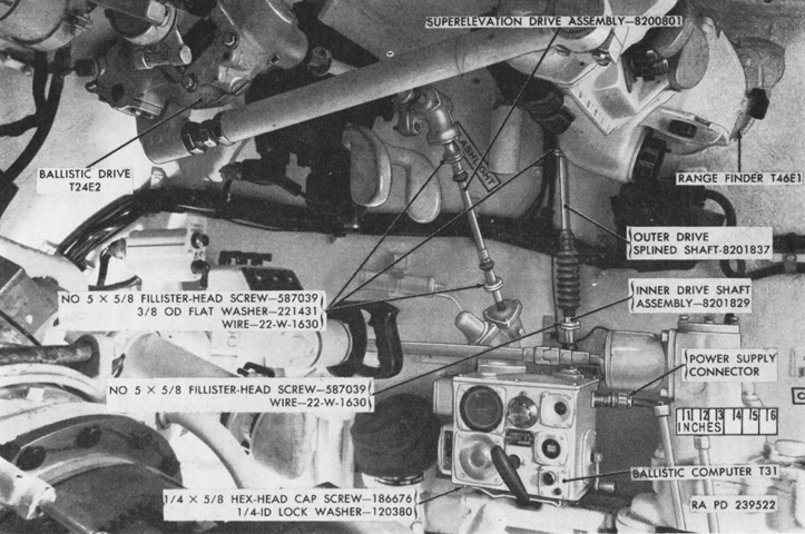
A wider view of the installed computer is given here, with connectors highlighted. (Picture from TM 9-6159 Field and Depot Maintenance Ballistic Computer T31.)
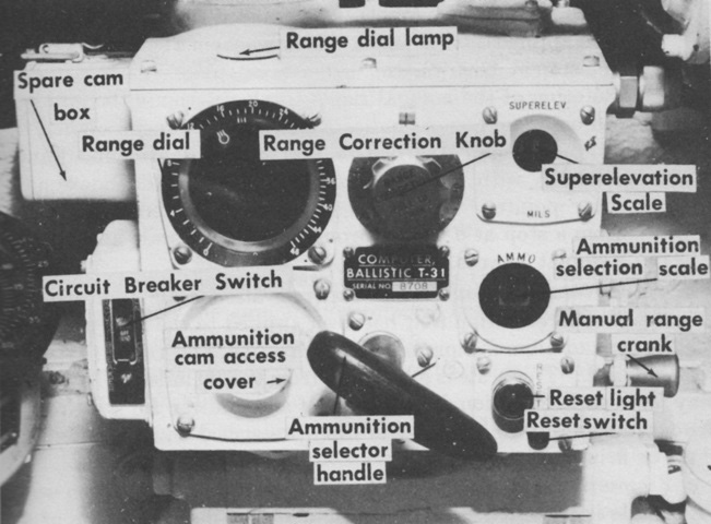
The controls of the ballistic computer T31 are labeled in this picture. (Picture from FM 17-79 Tank, 90-mm Gun, M48.)
The ballistic computer T31's internal gearing is diagrammed here. (Picture from TM 9-6159 Field and Depot Maintenance Ballistic Computer T31.)
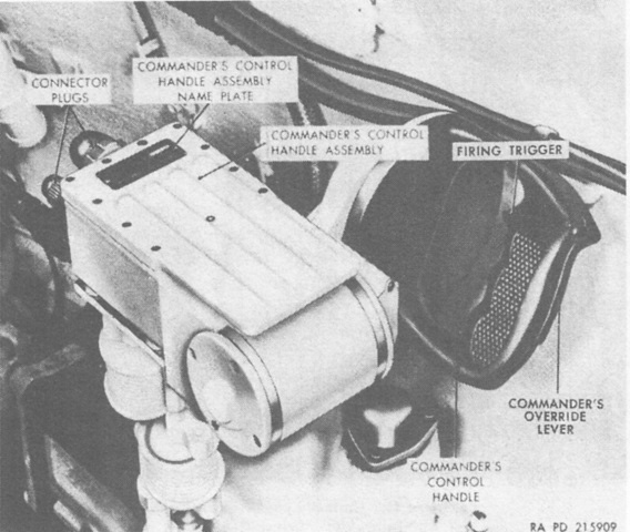
The commander was provided with a similar turret control handle as the gunner, except that the commander's had an override grip switch that would allow him to take control away from the gunner. The commander lacked the gun selector switches available to the gunner, however, so it was necessary for the gunner to have the appropriate weapon selected before the commander could fire from his position. (Picture from TM 9-7012 90-mm Gun Tank M48.)
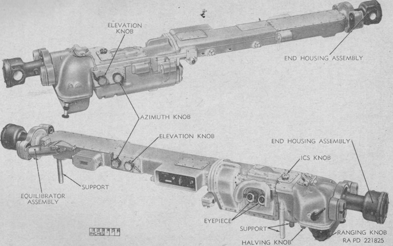
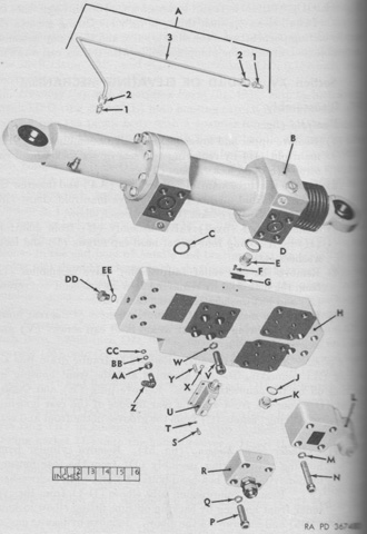
The rangefinder T46E1 is labeled from the front and rear. The T46E1's base length was 79" (200cm), it was graduated from 400 to 4,800 yards (460 to 4,400m), and it had 10x magnification with a 71-mil field of view. Overall, it was 85" (216cm) wide, 12" (30cm) tall, 14" (36cm) deep, and weighed 134.38lb (60.955kg) including the end housing assemblies. (Picture from TM 9-6023 Ordnance Maintenance Range Finder T46E1.)
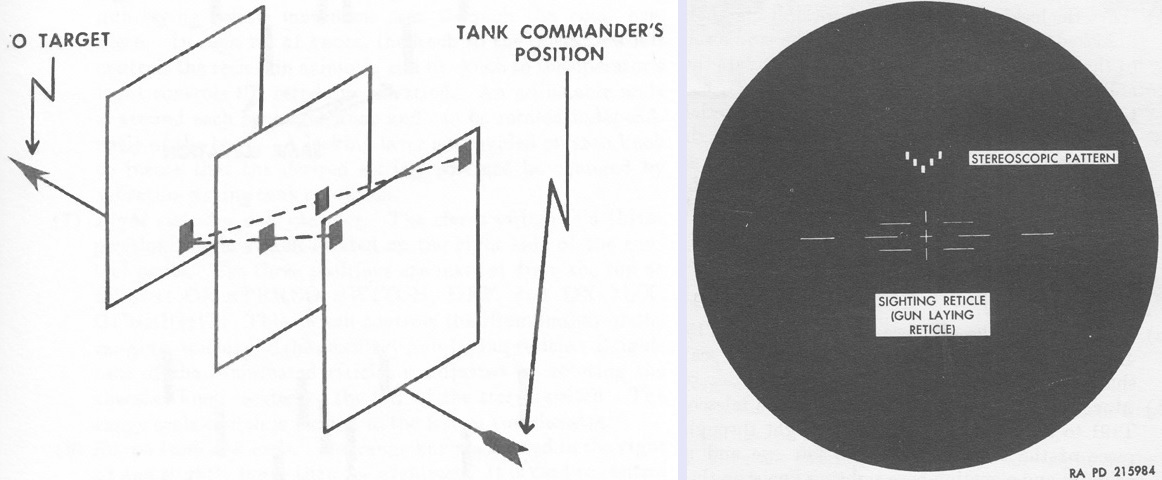
The principle of the stereoscopic rangefinder is illustrated on the left. The five marks of the stereo reticle would show in the eyepieces of the rangefinder, and when properly adjusted the reticle would appear so that the upper bars were closest and the lowest bar farthest away. The commander used the range knob to adjust the reticle so that the lowest bar appeared to be as far away as the target. The reticle pattern of the rangefinder is drawn on the right, with the stereoscopic pattern at the top and the gunlaying reticle beneath. The gunlaying reticle was similar to that in the gunner's periscope M20, M20A1, or M20A2, except that the rangefinder had only two vertical range lines instead of six. (Pictures from FM 17-79 Tank, 90-mm Gun, M48 and TM 9-7012 90-mm Gun Tank M48.)
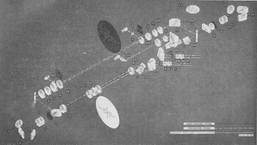
The T46E1's optical system is diagrammed in this schematic. A stereo reticle was provided for the left and right optical systems, while the main boresighting reticle was in the left optical line of sight. An auxiliary boresighting reticle could be projected into the right optical system if the left system was damaged.
Left sighting and collimating systems: A. End housing window. B. End housing penta reflector. C. End housing wedge. D. Range finder end window. E. Filter. F. Porro reflector assembly. G. Objective lens. H. Collective lens. J. Main boresight reticle. K. Collective lens. L. First erector lens. M. First 90-degree prism. N. Second erector lens. P. Second 90-degree prism. Q. Ocular prism. R. Field stop. S. Field lens. T. Eyelens. U. Stereo reticle window. V. Left stereo reticle. W. Collimator objective lens. X. Collimator wedge.
Right sighting and collimating systems: AA. End housing window. BB. End housing penta reflector. CC. End housing wedge. DD. Range finder end window. EE. Filter. FF. Compensator lenses. GG. Porro reflector assembly. HH. 90-degree prism. JJ. Objective lens. KK. Beam-splitter prism. LL. Ocular prism. MM. Field stop. NN. Field lens. PP. Eyelens. QQ. Stereo reticle window. RR. Right stereo reticle. SS. Collimator objective lens. TT. Collimator wedge. UU. ICS wedge. VV. Auxiliary boresight reticle. WW. Auxiliary boresight collimator lens. XX. Auxiliary boresight objective lens. YY. Porro prism. ZZ. Range viewing prism. (Picture from TM 9-6023 Ordnance Maintenance Range Finder T46E1.)
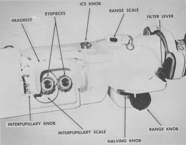
The eyepieces of the rangefinder are shown here. The interpupillary knob adjusted the eyepieces so that they could be from 58-72mm (2.3-2.8") apart. The halving knob allowed adjustment of the right-side ranging reticle when it appeared at a different elevation from the left reticle. The ICS (internal correction system) knob allowed the individual commander to adjust an individual rangefinder to his personal vision and use. He would select a target of known range and then use the ICS knob if necessary to correct the rangefinder reading until it was accurate. Ten rangings were averaged to obtain that commander's ICS setting for that rangefinder. The range scale moved when the range knob was turned; the range knob adjusted the apparent movement of the ranging reticle or indexed a given range on the range scale. The filter lever introduced or withdrew filters into view. (Picture from FM 17-79 Tank, 90-mm Gun, M48.)
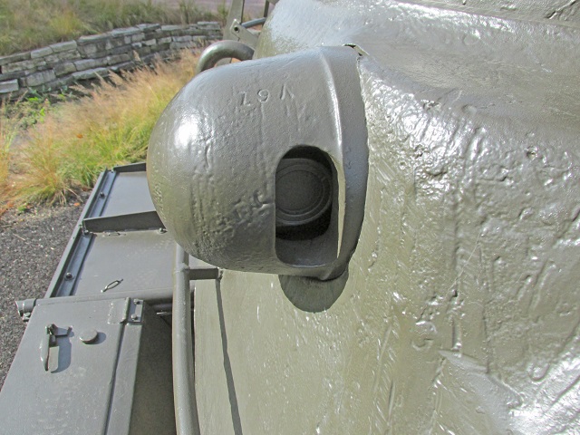
A closeup of the armored blister protecting the right-hand aperture of the stereoscopic rangefinder T46E1 is shown here.
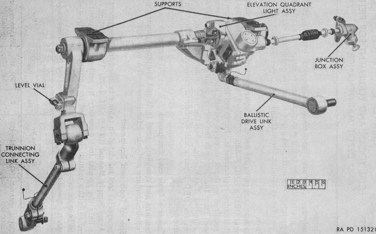
The ballistic drive T24E2 is shown from the left front. Mounted to the turret roof by two supports and a flange on the junction box, the T24E2 connected the ballistic computer, the 90mm gun mount, the head of the gunner's periscope M20/M20A1/M20A2, and the rangefinder. The computer introduced ballistic motion to the range drive through the computer output shaft, and the ballistic drive depressed the line of sight of the periscope and rangefinder by an appropriate amount. When the reticle was raised back on target, the gun was then at the correct superelevation. (Picture from TM 9-6163 Ordnance Maintenance Ballistic Drive T24E2.)
The contents of the superelevation box assembly of the ballistic drive T24E2 are shown in this exploded view. The complete ballistic drive was 39" (99cm) long, 15" (38cm) wide, 9¼" (23.5cm) high, and weighed 135lb (61.2kg). (Picture from TM 9-6163 Ordnance Maintenance Ballistic Drive T24E2.)
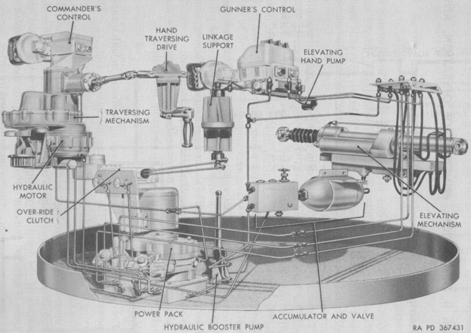
An overview of the traversing and elevating systems is diagrammed. During manual operation, the traverse mechanism gear train was actuated directly by the hand traversing drive, while during power traverse the gear train was actuated and controlled by an hydraulic motor. Manual and power elevation were both hydraulic. Manual operation used the elevating hand pump to pump oil to the elevating mechanism, while power elevation used an hydraulic motor similar to the power traverse system. (Picture from TM 9-7013-2 Ordnance Maintenance Traversing and Elevating System for 90-mm Gun Tank M48 (T48).)
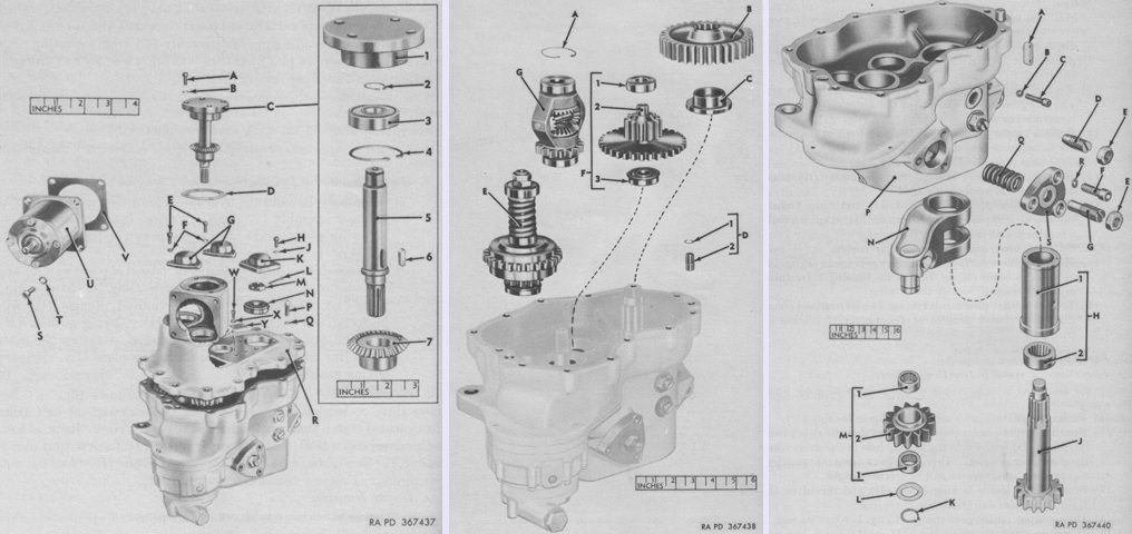
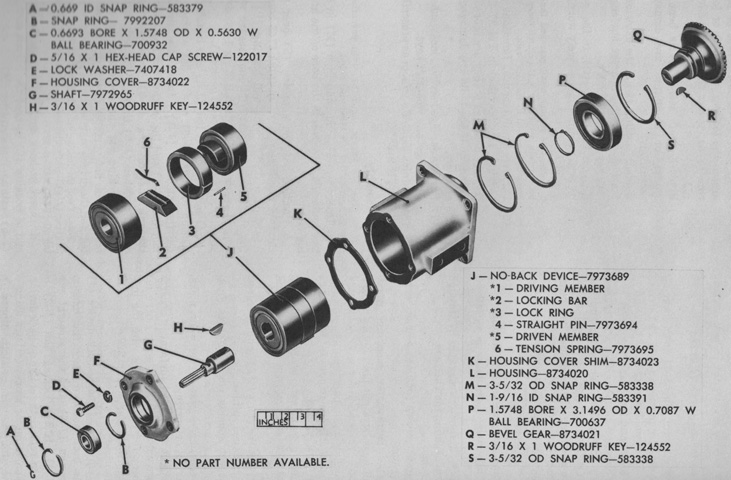
Three exploded views of the White Motor traversing mechanism are provided above. Force was received either via the hand traversing drive through the Nobak driven gear or via the hydraulic motor driven gear; when power was being applied from one of these sources, the other was locked out. The Nobak and hydraulic driven gears were splined to a differential power input gear. The traversing drive was 20¼" (51.44cm) high, 25½" (64.8cm) long, 12½" (31.8cm) wide, and weighed 216.0lb (97.98kg). The legend for the left image is: A. 5⁄16 x ¾ socket-head cap screw. B. 0.334" (0.848cm) ID, 0.3808" (0.9672cm) OD, 0.0781" (0.198cm) thick lockwasher. C. Nobak driven shaft assembly. 1. Cover. 2. 25⁄32" (1.9844cm) snap ring. 3. 0.7874" (2.000cm) bore, 2.0472" (5.1999cm) OD, 0.5906" (1.500cm) width ball bearing. 4. 2.834" (7.198cm) snap ring. 5. Shaft. 6. ¼ sq x ⅞ long gear key. 7. Bevel gear. D. Nobak driven shaft cover shim. E. 5⁄16 x ¾ socket-head cap screw. F. 0.334" (0.848cm) ID, 0.3808" (0.9672cm) OD, 0.0781" (0.198cm) thick lockwasher. G. Overhead clutch shaft and cluster gear cover. H. 5⁄16 x ¾ socket-head cap screw. J. 0.334" (0.848cm) ID, 0.3808" (0.9672cm) OD, 0.0781" (0.198cm) thick lockwasher. K. Output pinion cap. L. Split cotter pin. M. ¼" (0.26cm) hex slotted locknut. N. 1.1811" (3.0000cm) bore, 2.4408" (6.1996cm) OD output pinion ball bearing. P. 7⁄16 x 1½ socket-head cap screw. Q. 0.529" (1.34cm) ID, 0.848" (2.15cm) OD, 11⁄64" (0.436563cm) thick lockwasher. R. Upper housing. S. ⅜ x 1 socket-head cap screw. T. 0.382" (0.970cm) ID, 0.460" (1.17cm) OD, ⅛" (0.318cm) thick lockwasher. U. Nobak mechanism. V. Nobak shim. W. No. 10 x ⅜ round-head screw. X. No. 10 light lockwasher. Y. Traversing gear box nameplate.
The legend for the center image is: A. 2 3⁄16" (5.5563cm) snap ring. B. Output pinion gear. C. Output pinion gear spacer. D. Upper and lower housing locating dowel pin with ring assembly. 1. 0.591" (1.50cm) ID, 0.646" (1.64cm) OD, 0.055" (0.14cm) thick snap ring. 2. 0.591 x 1⅜ long grooved dowel pin. E. Overload clutch assembly. F. Cluster gear with bearing assembly. 1. 0.7874" (2.000cm) bore, 2.0472" (5.1999cm) OD, 0.5906" (1.500cm) width ball bearing. 2. Intermediate cluster gear. 3. 0.7874" (2.000cm) , 2.0472" (5.199cm) OD, 0.5906" (1.500cm) width ball bearing. G. Differential assembly.
The legend for the right image is: A. Gear box shear key. B. 0.269" (0.683cm) ID, 0.3158" (0.8021cm) OD, 0.0781" (0.198cm) thick lockwasher. C. ¼ x ⅞ socket-head cap screw. D. Sleeve locking screw. E. 3⁄16" (0.4763cm) hex-hd jam nut. F. ½ x 1½ socket-head screw. G. Output pinion idler arm stop. H. Sleeve with bearing assembly. 1. Sleeve. 2. 1.7500" (4.4450cm) shaft diam, 2.1200" (5.3848cm) OD, 1.5000" (3.8100cm) width needle bearing. J. Output pinion. K. 1½" (3.8cm) snap ring. L. Idler retaining washer. M. Idler pinion with bearing assembly. 1. 1.5000" (3.8100cm) shaft diam, 1.8750" (4.7625cm) OD, 0.7850" (1.994cm) width needle bearing. 2. Pinion. N. Idler pinion arm. P. Lower housing. Q. Overload clutch spring. R. ½" (1.3cm) lock washer. S. Idler pinion arm cap. (Picture from TM 9-7013-2 Ordnance Maintenance Traversing and Elevating System for 90-mm Gun Tank M48 (T48).)
Components of the Nobak mechanism are shown above. This mechanism allowed the gunner's hand traversing drive to apply force to the traversing mechanism while preventing the traversing mechanism from transmitting force back into the hand drive. When a reverse force was applied, the Nobak mechanism locked. A. 2.834" (7.206cm) snap ring. B. Bevel gear with bearing assembly. 1. Gear. 2. 1.3780" (3.5001cm) bore, 2.8346" (7.1999cm) OD, 0.6693" (1.700cm) width ball bearing. 3. 1⅜" (3.493cm) snap ring. C. 5⁄32 x ⅞ bevel gear key. D. Housing with cover shaft assembly. 1. 2.834" (7.198cm) snap ring. 2. Housing. 3. Nobak assembly. 4. 1.5748" (4.0000cm) snap ring. 5. 5⁄32 x ⅞ shaft key. 6. 1.5748" (4.0000cm) snap ring. 7. Housing cover. 8. 5⁄16 x 1 socket-head cap screw. 9. 0.334" (0.848cm) ID, 0.3808" (0.9672cm) OD, 0.0781" (0.198cm) thick lockwasher. 10. Driven shaft with gear, cover, and bearing assembly. a. Shaft. b. 0.6693" (1.700cm) bore, 1.5748" (4.0000cm) OD, 0.5630" (1.430cm) width ball bearing. c. 0.669" (1.70cm) snap ring. 11. 0.125 diam x 13⁄16 lg reaction pin. (Picture from TM 9-7013-2 Ordnance Maintenance Traversing and Elevating System for 90-mm Gun Tank M48 (T48).)

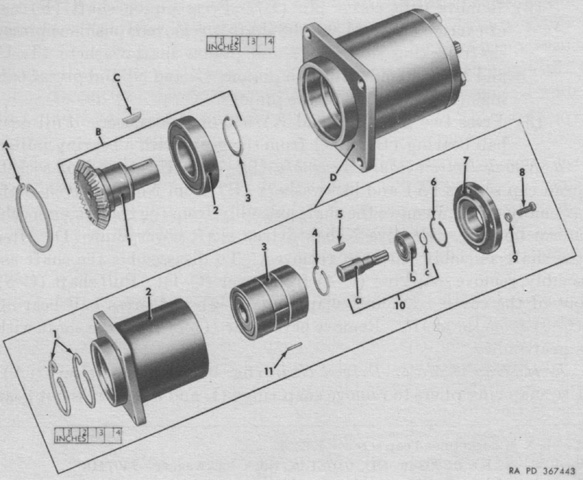
Front and rear views of the Oilgear traversing and elevating power pack are at the left and right, respectively. The assembly consisted essentially of an electric motor, a drive gearcase, traversing and elevating hydraulic pumps, and an oil reservoir with a built-in gear pump and oil filter. The power pack's net weight was 269lb (122kg), with 55lb (25kg) taken up by the traversing hydraulic pump, 57lb (26kg) by the elevating hydraulic pump, 34lb (15kg) by the 1½ gallon (5.7L) oil reservoir and gear pump, 22.5lb (10.2kg) by the hydraulic motor, 11.80lb (5.352kg) by the Greer Hydraulics accumulator and valve, and 3.80lb (1.72kg) by that company's hydraulic booster pump. (Picture from TM 9-7013-2 Ordnance Maintenance Traversing and Elevating System for 90-mm Gun Tank M48 (T48).)
A partially exploded view of the Seren Tool Company elevating mechanism is provided here. The front end of the cylinder assembly was secured to the top of the turret, and the rear was attached to the gun mount. The manifold contained five valves: a lower locking valve controlling flow between the elevating mechanism and the power pack; an upper locking valve controlling flow between the elevating mechanism and the elevating hand pump; a relief valve that attenuated internal pressure from oil thermal expansion or external forces acting on the gun; and two other relief valves acting as relief valves for elevation and depression, respectively, to provide smooth motion and avoid stepping. Oil flowed from the manifold into the cylinder assembly to move the gun in elevation: from the rear flange to the front flange for elevation and from the front flange to the rear flange for depression. It weighed 252lb (114kg), was 31 9⁄32" (79.45438cm) long overall, and 14¼" (36.20cm) high overall. A. Hydraulic drain line assembly. 1. ¼" (0.64cm) compression tube fitting safety sleeve. 2. ¼" (0.64cm) safety sleeve compression tube fitting nut. 3. ¼" (0.64cm) OD, 0.035" (0.089cm) wall, seamless tubing. B. Cylinder assembly. C. ⅛" (0.318cm) thick, 1 1⁄16" (2.6988cm) ID O-ring gasket. D. ⅛" (0.318cm) thick, 1 1⁄16" (2.6988cm) ID O-ring gasket. E. Plug. F. No. 10 x 3½" (8.9cm) roundhead drive screw. G. Nameplate. H. Manifold. J. O-ring gasket. K. Hex-head plug. L. Relief (adjustable) valve assembly. M. 0.636" (1.62cm) ID, 0.747" (1.90cm) OD, 0.1742" (0.4425cm) thick lockwasher. N. ⅝ x 3¼ socket-head cap screw. P. ⅝ x 2 socket-head cap screw. Q. 0.636" (1.62cm) ID, 0.747" (1.90cm) OD, 0.1742" (0.4425cm) thick lockwasher. R. Relief (fixed) valve assembly. S. No. 10 x ⅝" (1.59cm) socket-head cap screw. T. 0.194" (0.493cm) ID, 0.240" (0.610cm) OD, 0.047" (0.12cm) thick lockwasher. U. Upper and lower locking valve assemblies. V. ⅝ x 2¼" (5.72cm) socket-head cap screw. W. 0.636" (1.62cm) ID, 0.747" (1.90cm) OD, 0.1742" (0.4425cm) thick lockwasher. X. 1⁄16" (2.6988cm) thick, ⅜" (0.953cm) ID, O-ring gasket. Y. 1⁄16 x ¼" (0.64cm) dowel pin. Z. ¼" (0.64cm) tube, 7⁄16" (1.111cm) one end, ¼" (0.64cm) other end manifold elbow. AA. 7⁄16" (1.111cm) manifold elbow nut. BB. 0.577" (1.47cm)x 0.1169" (0.2969cm) x 0.094" (0.24cm) manifold elbow ring. CC. 0.072" (0.18cm) thick, 0.351" (0.892cm) ID O-ring gasket. DD. 9⁄16" (1.429cm) x 7⁄16" (1.111cm) hex-head plug. EE. 0.468" (1.19cm) ID,0.624" (1.58cm) OD, 0.078" (0.20cm) thick gasket. (Picture from TM 9-7013-2 Ordnance Maintenance Traversing and Elevating System for 90-mm Gun Tank M48 (T48).)
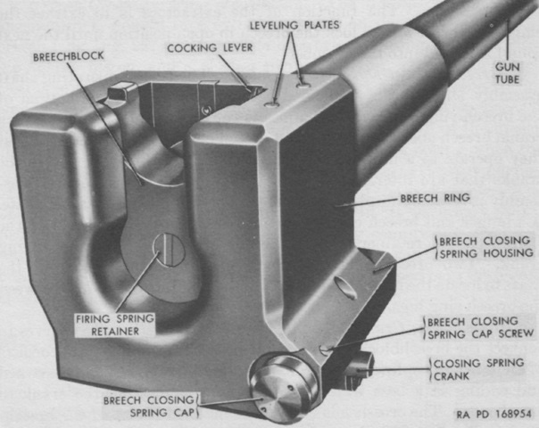
The breech of the 90mm gun M41 is shown here. It was ballistically identical to the 90mm gun M36 found in the M47 Patton 47, but was lighter and featured a quick-change tube that, thanks to interrupted threads that connected it to the breech ring, could be removed without dismounting the gun from the turret. The 90mm gun M41 could fire ammunition used in the earlier 90mm gun M3 series, but the inverse was not true for projectiles using the cartridge case T24 designed for solely the 90mm gun M41, as its less-tapered and longer shoulder would not usually chamber in the earlier guns. (Picture from TM 9-7012 90-mm Gun Tank M48.)
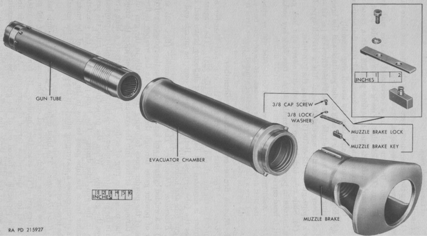
The muzzle of the 90mm gun is illustrated in this image, with the early round muzzle brake and bore evacuator chamber shown disassembled. The orifices over which the evacuator chamber fit are visible on the gun tube to the upper left. The gun tube's estimated life was 1,000 equivalent full charge rounds. Each armor-piercing capped M82 round equaled one equivalent full charge. The complete gun weighed 2,370lb (1,076kg), and the tube itself weighed 1,582lb (717.6kg). (Picture from TM 9-7012 90-mm Gun Tank M48.)
The right side of the combination gun mount M87 is seen here. The gun shield was bolted to the cradle, and also was mounted to the trunnions by bosses on each side. The M87 weighed 2,845lb (1,290lb) without the elevating mechanism, and 3,097lb (1,405kg) including it. Any of four elevating mechanisms could be found mated to the M87: elevating assembly ORD No. 7997599 was the original design; 8370388 was developed from 7997599 and featured a thicker front housing flange, relocated preformed packing, backup rings for the packing, and preformed packing for the piston rod rear guide; 8382217 was developed from 8370388 and replaced the manifold needle valve with packing and a plug to close the bore; and the rear housing flanges of 8686541 no longer had ports. (Picture from TM 9-7012 90-mm Gun Tank M48.)
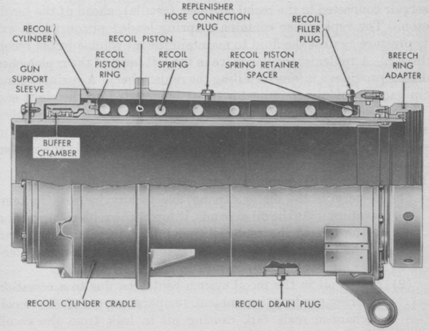
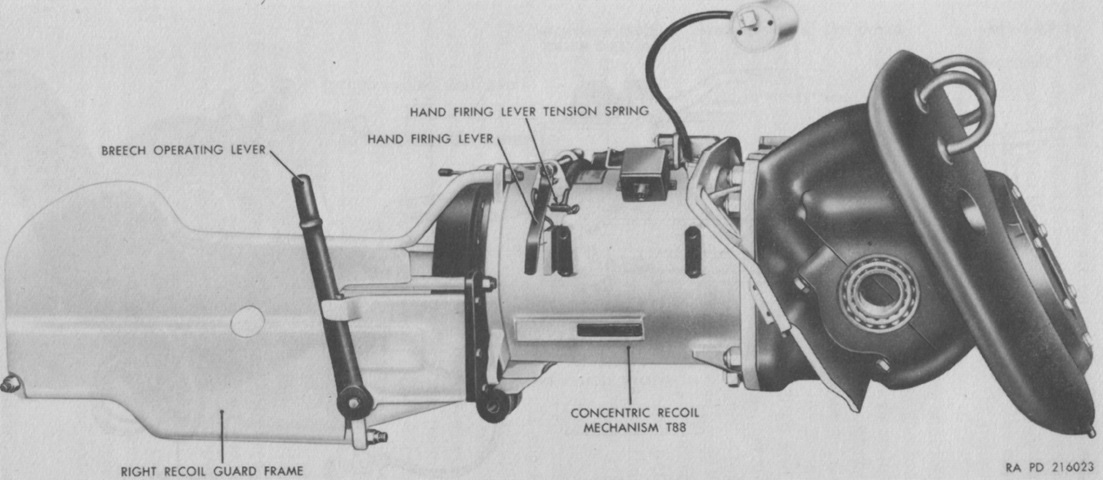
The concentric recoil mechanism T88 was a hydro-spring constant recoil distance type. The gun cradle formed the outer cylinder of the recoil mechanism and was concentric with and completely overlapped the gun's recoil surface. Normal recoil distance was 12" (30cm), and maximum was 13.5" (34.3cm). When the gun was fired, the recoil piston, attached to the breech ring by the breech ring adapter, traveled to the rear along with the breech ring. Hydraulic fluid behind the piston ring was forced around it through the space between the ring and the cylinder. The cylinder's tapered wall increasingly resisted this flow of fluid as the gun recoiled, and the compression of the recoil spring assisted with arresting the recoil action. The compressed recoil spring then returned the gun to battery. When the gun reached 3" (7.6cm) from battery, the tapered portion of the recoil piston would enter the buffer chamber. This would force hydraulic fluid from the chamber, and the piston's taper would progressively restrict the fluid's escape, thereby softening the counterrecoil action. Including the replenisher, the mechanism had a capacity of 5.5 gallons (21L) of fluid. (Picture from TM 9-7012 90-mm Gun Tank M48.)
The turret is shown here being lifted from the hull, with the turret basket visible. Note that this early T48 does not have the small track tensioning idler wheel fitted behind the rear road wheel. The turret assembly weighed 30,000lb (13,600kg) including the 90mm gun and mount. (Picture from TM 9-7013-1.)
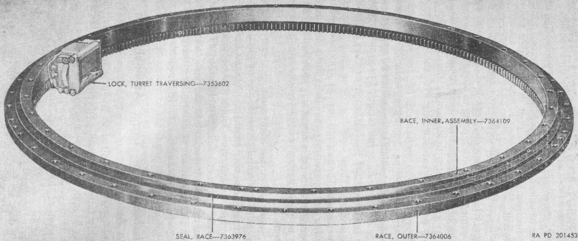
The turret race assembly operated similarly to a large thrust ball bearing with an outer race assembly secured to the hull by forty-eight ¾-16NF-2 x 3¾ bolts and an inner race assembly secured to the turret by twenty-five ⅞-14NF-3 x 2⅛ captive bolts. (Picture from TM 9-7013-1.)
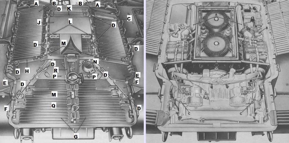
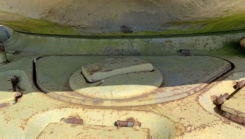
Features of the top deck are illustrated in the left image. A. Fuel tank filler cover. B. Engine access side grille door. C. Auxiliary engine exhaust muffler. D. Lifting eye. E. Transmission access side door. F. Transmission access side plate. G. Transmission access grille door. H. Cross beam. J. Engine exhaust. K. Engine access center grille door. L. Front support beam. M. Locking plate. N. Transmission oil filler cover. P. Transmission access center plate. Q. Rear traveling support beam. R. Gun traveling lock.
On the right, the engine and transmission compartments have been uncovered. A. Carburetor intake duct. B. Fire extinguisher right discharge nozzle. C. Transmission mounting nut and washer. (Picture from TM 9-7012 90-mm Gun Tank M48.)
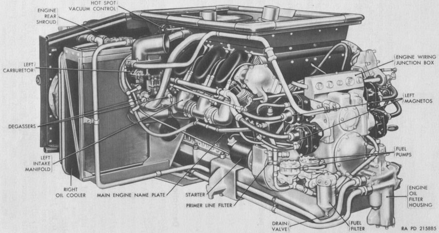
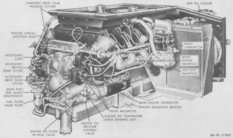
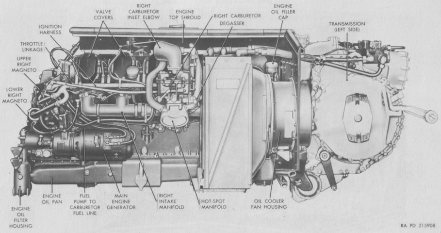
The accessory end, or front, of the AV-1790-7B engine is shown here. The left and right sides of the engine were determined by looking at the engine from the accessory end. The -7 series differed from the earlier -5 series by using the cylinders from the AOS-895-3 engine found in the 76mm gun tank M41. The -7B, debuting in August 1954, was fitted with a stronger 300 ampere generator instead of the earlier 150 ampere unit. The later -7C had two fuel filters mounted to each oil cooler. (Picture from TM 9-7012 90-mm Gun Tank M48.)
The engine was 73.70" (187.2cm) long, 59.83" (152.0cm) wide, and 40.84" (103.7cm) tall. Bore and stroke were both 5.75" (14.6cm) for a displacement of 1,790in³ (29.3L). Its compression ratio was 6.5:1, idle speed was 650rpm, and maximum governed speed under full load was 2,800rpm. When fitted with its flywheel and transmission adapter, the AV-1590-5B weighed 2,581lb (1,171kg), while the AV-1790-7, -7B, and -7C were 2,647lb (1,201kg). (Picture from TM 9-7012 90-mm Gun Tank M48.)
The engine, transmission, and oil coolers could be removed as one power plant unit. (Picture from TM 9-7012 90-mm Gun Tank M48.)
The cross-drive transmission was a combined transmission and steering unit with integral disc brakes. Steering could be accomplished in both forward speed ranges as well as reverse. When in neutral, steering would spin the tracks in opposite directions. It weighed 2,946lb (1,336kg) dry, and was 30" (76cm) long, 40.375" (102.55cm) tall, and ~40" (~100cm) wide over the drive flanges. (Picture from TM 9-7012 90-mm Gun Tank M48.)
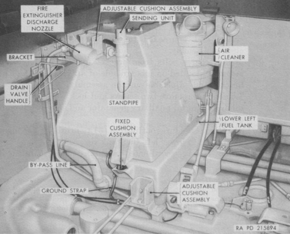
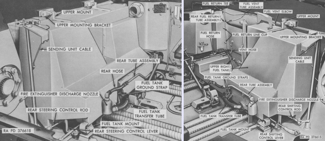
The left-side fuel tanks are shown here. A similar setup was found on the right side of the engine compartment. (Picture from TM 9-7012 90-mm Gun Tank M48.)

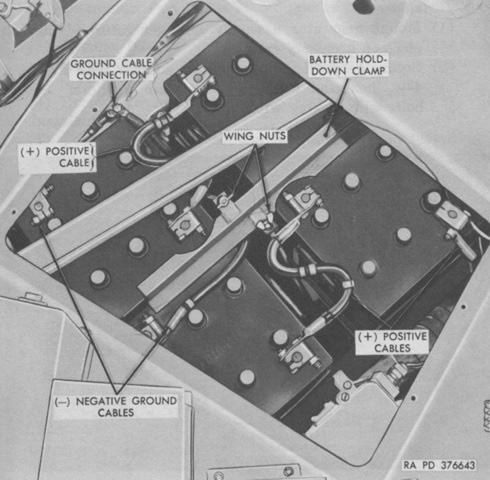
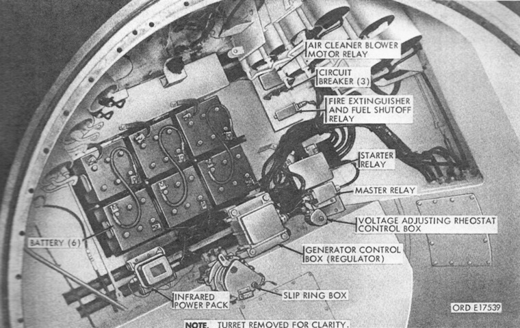
Under the crew compartment floor, four 12-volt, 100-ampere batteries were connected in series parallel to form a 200-ampere, 24-volt source. (Picture from TM 9-7012 90-mm Gun Tank M48.)
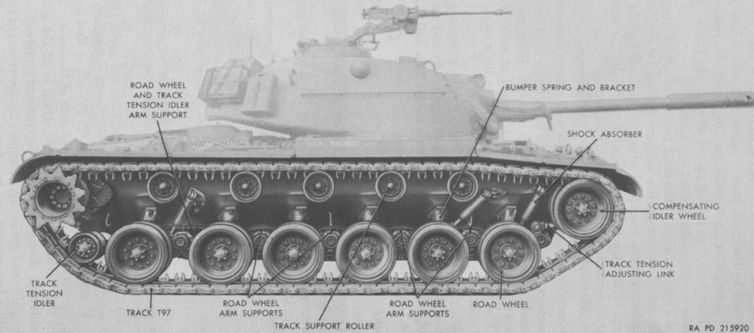
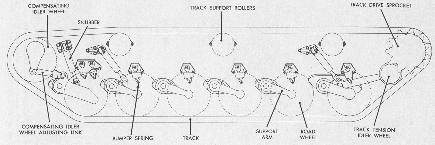
Suspension components are detailed in this image. (Picture from TM 9-7012 90-mm Gun Tank M48.)
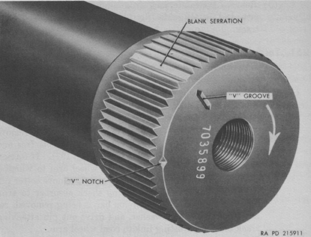
Each torsion bar was marked with its part number and an arrow indicating its loading torque direction. Not all torsion bars were interchangeable. During installation, the blank serration on the torsion bar was mated to a blank serration on the torsion bar anchor plug. The "V" notch indicated the location of the blank serration on the inner end of the torsion bar, while the "V" groove indicated the same for the outer end of the torsion bar. (Picture from TM 9-7012 90-mm Gun Tank M48.)
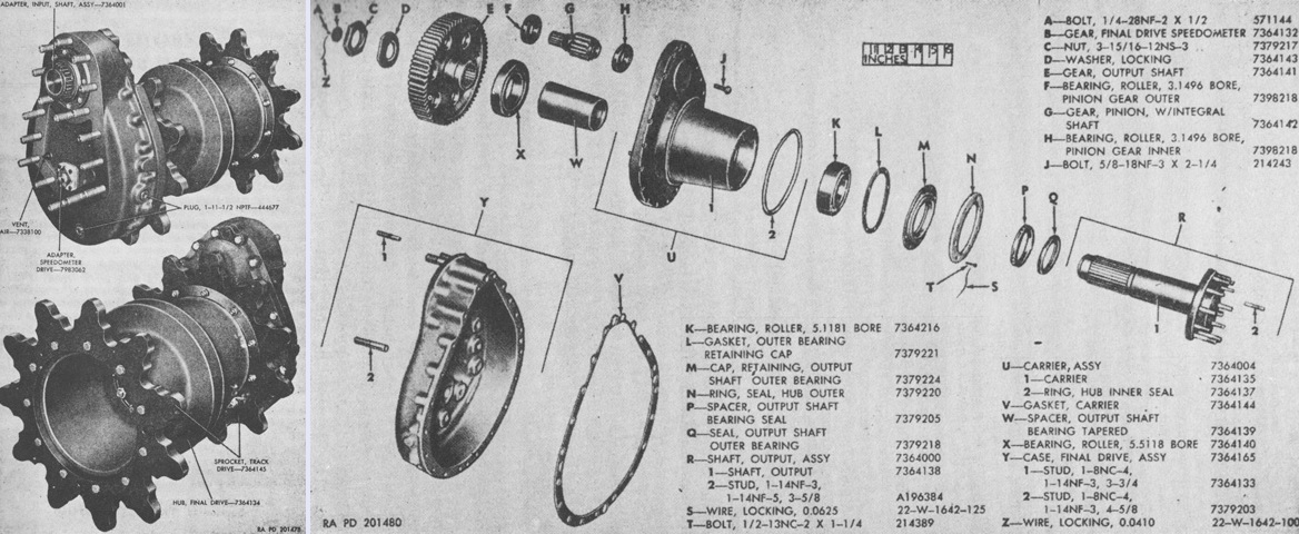
Assembled and exploded views of the left final drive are shown on the left and right, respectively. A constant 7.08:1 speed reduction was obtained by a pair of spur gears. The left-side final drive incorporated a speedometer adapter with an overall drive ratio reduction of 4.97:1. Two types of final drives could be found: left final drive 7364131 and right final drive 7364130 were preferred, and had two dowel pins in the carrier assemblies to align the carrier and case assemblies. Alternate final drives 7992428 (left) and 7992429 (right) featured four such dowel pins. (Picture from TM 9-7013-1.)

The final drive mounting is seen from the inside of the hull. (Picture from TM 9-7012 90-mm Gun Tank M48.)
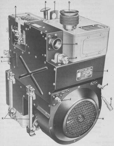
The General Motors A-41-2 auxiliary engine was a 14.5-horsepower, 1-cylinder, 4-cycle, air-cooled, constant-speed gasoline engine, governed at 3,100rpm at full load. It took fuel from the main engine fuel tanks, and was combined with the generator into one integral unit. Bore and stroke were 3.625" (9.208cm) and 4" (10cm), respectively. This unit could recharge the tank's batteries, provide electrical power for systems with the main engine off, supplement the main engine's current generation, or provide heat for the engine compartment during cold temperatures. A. Carburetor adjustment opening. B. Manual starting handle. C. Lifting eye. D. Exhaust outlet. E. Auxiliary generator and engine name plate. F. Negative terminal. G. Fuel line quick disconnect. H. Cooling air inlet. J. Positive terminal. K. Guide rails. L. Magneto adjustment hole cover. M. Timing hole cover. N. Carburetor air inlet. P. Control cable receptacle cover. (Picture from TM 9-7012 90-mm Gun Tank M48.)
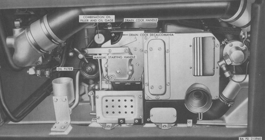
This view is looking down at the installed auxiliary engine and generator. It could be started via a control box in the driver's compartment, or manually when there was not enough current. (Picture from TM 9-7012 90-mm Gun Tank M48.)
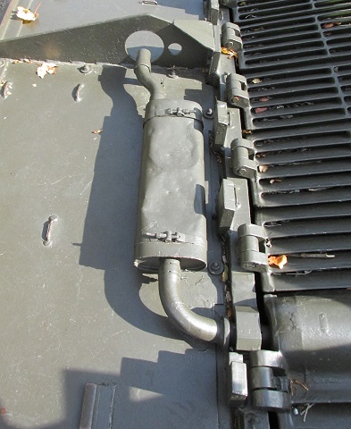
The muffler for the auxiliary engine was mounted on the right fender just aft of the turret.
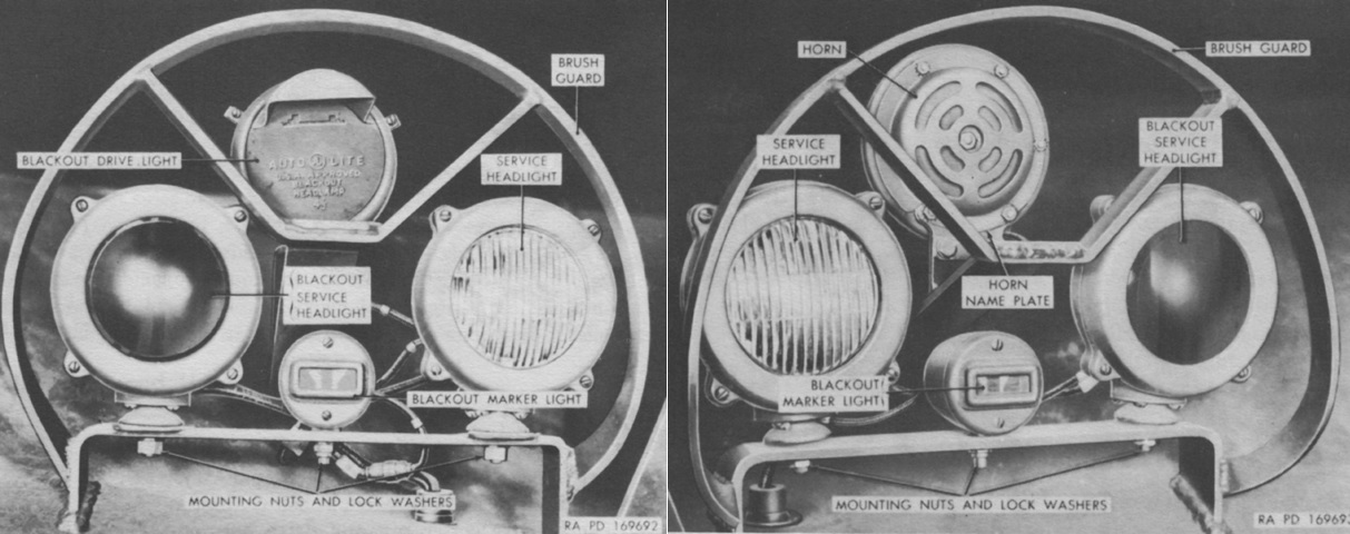
The left and right headlight clusters are displayed here on the left and right, respectively. (Picture from TM 9-7012 90-mm Gun Tank M48.)
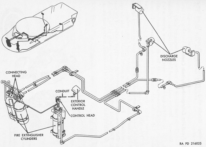
Three 10lb (4.5kg) CO2 fire extinguisher cylinders were mounted in the driver's compartment, with tubing and nozzles that routed the contents to the engine compartment. The cylinders were simultaneously activated via a pull handle on the left cylinder or by the exterior control handle on the hull front. In addition, a portable 5lb (2.3kg) CO2 extinguisher was kept on the left side of the 90mm ammunition stowage box on the turret platform. (Picture from TM 9-7012 90-mm Gun Tank M48.)
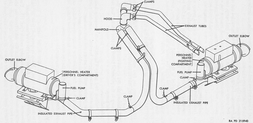
A schematic of the personnel heater layout is sketched here. The heaters were two Perfection E500-24 gasoline-fueled units, one in the driver's compartment and one attached to the hull wall in the crew compartment. Controls for both heaters were in the driver's compartment. (Picture from TM 9-7012 90-mm Gun Tank M48.)
The glacis of the M48C was marked with a prominent weld bead to prevent confusion with tanks that were armored to the correct specification. (Photo by Richard S. Eshleman.)
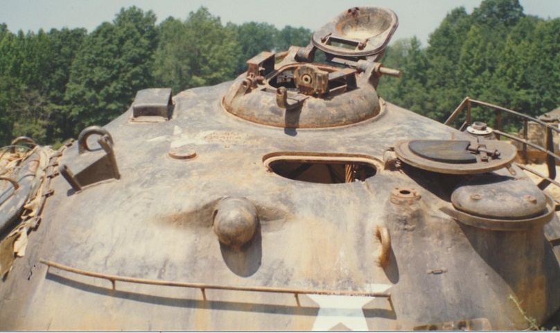
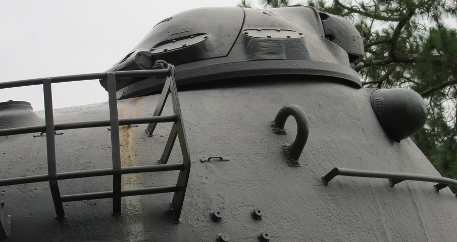
The top of the turret is shown here in splendid detail. Both the loader's D-shaped hatch and the commander's cupola hatch are open. The openings for the periscopes in the commander's hatch door and the front of the cupola can be seen. (Photo by Richard S. Eshleman.)
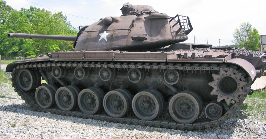
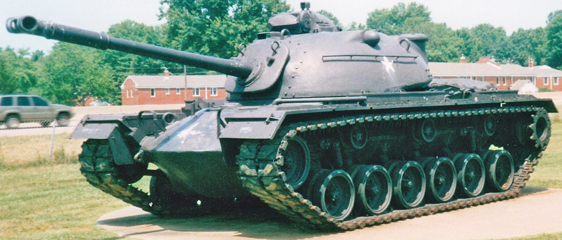
The large cupola, five return rollers, and rear auxiliary track tensioning wheel identify this vehicle as an M48A1 or M48A2 tank. The shock absorbers on the first two and last road wheels can be seen, and stowage boxes are present on the fenders. The turret ventilating blower cover can be seen on the top of the turret rear, just in front of the stowage basket. A mount for a water can is placed low on the turret rear. A grab rail is welded to the turret below the lifting eye. The left armored blister for the stereoscopic rangefinder is near the middle of the upper side of the turret.
The ventilator in the turret's left rear can be seen, and the structure of the turret basket and water can mounts on the turret sides are apparent.
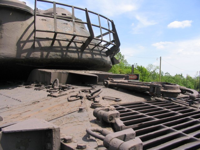
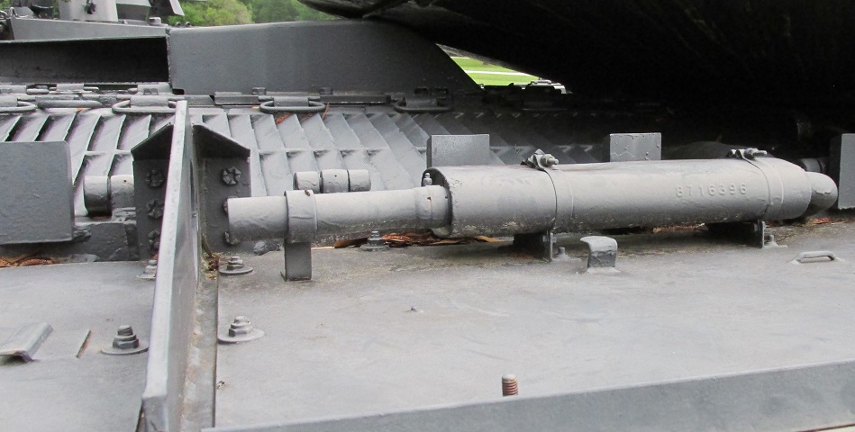
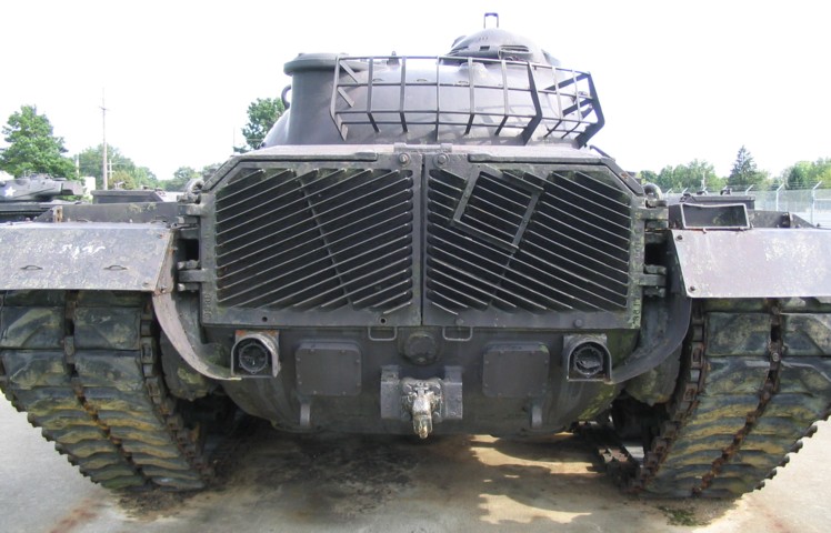
The grille doors toward the rear of the tank were for transmission access, while those to either side of the exhaust provided access to the engine. The gun travel lock is folded down onto the transmission access center plate. Numerous lifting eyes are present to enable the various grilles and plates to be swung open.
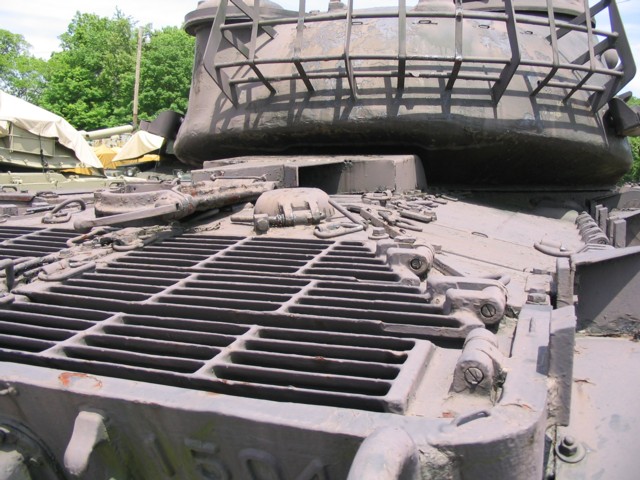
The right-side transmission and engine access grilles can be seen here, as well as a closer view of the gun travel lock in the stowed position. As above, the cover next to the gun travel lock protected the engine oil filler.
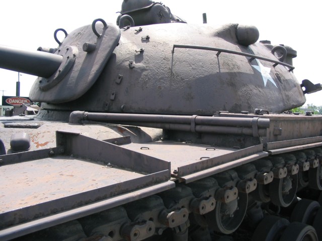
The M48 and M48A1 had two gasoline-powered personnel heaters installed along the left side of the hull. The exhausts for these heaters were routed through the front hull next to the driver's hatch as seen here. The guard in front of the heater exhausts housed handles for external activation of the vehicle's fire extinguishers. Around the gun shield are mounts for a cover, and through the gun shield are protrusions for the coaxial machine gun (on the cannon's left), and the gunner's direct sight telescope on the opposite side of the main gun.
The left rear corner of the larger driver's hatch was extended to mirror its right side; this can be contrasted with the earlier design.
The Aircraft Armaments cupola is sketched here, with the rear hatch in the open position. The aperture for the turret-type M2HB machine gun can be seen, as well as the vision blocks around the base and the periscope guard on top. The cupola was 14.875" (37.783cm) tall without the periscope, 38.375" (97.473cm) in diameter, 48.8125" (123.384cm) long without the machine gun, and weighed 1,400lb (635kg). (Picture from TM 9-1005-219-35.)
When M48A1s were created by replacing the original cupola on M48s manufactured with the large driver's hatch, an adapter ring (labeled "6" in the image) was necessary to mount the cupola to the turret flange. The ring assembly increased the height to 16.4375" (41.7513cm) without the sight, the diameter to 41" (104cm), and the weight to 1,670lb (758kg). (Picture from TM 9-1005-219-35.)
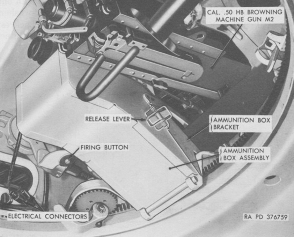
The outline of the door in the rear of the commander's cupola can be seen in this image, and its hinge is at the bottom next to one of the covered vision blocks. Five vision blocks ringed the bottom of the cupola, and the commander was provided with a periscope M28 in the top for using the machine gun, which was fed from a 100-round box magazine. The cupola was provided with an interlock so that the commander secure it into alignment with the main gun, which then allowed the cupola periscope to be used as an auxiliary target designation means. Testing in 1958 found that the cupola traverse could be affected or locked by strikes from .50 and .60 caliber armor-piercing (AP) ammunition fired at the base of the cupola from a 15° downward angle. Caliber .50 ball and armor-piercing ammunition could penetrate and fragment the vision blocks, while caliber .30 AP caused fragmentation but did not penetrate the vision blocks. Caliber .30 ball ammunition produced bullet splash that entered the cupola from the sides and bottom of the machine gun cradle as well as from the bottom seam of the cupola hatch. Strikes from caliber .30 ball also could adversely affect the elevation of the machine gun. No direct penetrations of the cupola armor were achieved with caliber .50 AP M2 or 20mm AP M95 fired at a 15° downward angle, even at impact velocities exceeding the typical muzzle velocities of these rounds.
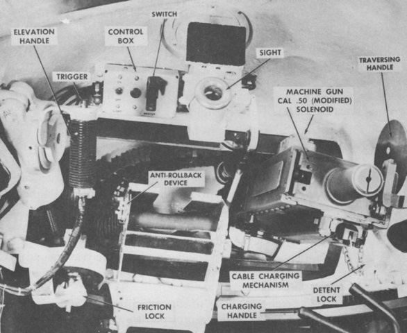
The interior of the commander's cupola is shown here. The interlock that allowed the cupola to remain aligned with the turret is labeled as the detent lock. Note that the machine gun is mounted on its left side, and the ammunition box has been omitted in the image. (Picture from FM 17-79 Tank, 90-mm Gun, M48.)
With the gun on its left side, expended casings were ejected to the right side of the cupola. The right side rangefinder blister is in the foreground.
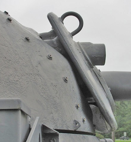
The thickness and contour of the main gun shield can be gleaned from this picture. Lifting eyes were welded to the upper corners, attachments for a canvas cover can be seen on the turret, and the aperture for the gunner's T156E1 telescope is below the lifting eye. The series of 1958 tests performed on the cupola also strove to see if the gun shield could be jammed by 20mm armor-piercing projectiles fired from a 15° overhead angle to simulate aircraft fire. The gun's elevation was not hindered during the evaluation, although turret traverse was able to be fouled by caliber .50 ball, caliber .60 armor-piercing, and 20mm armor-piercing strikes to the turret ring dust shield, lower turret edge, and hull top.
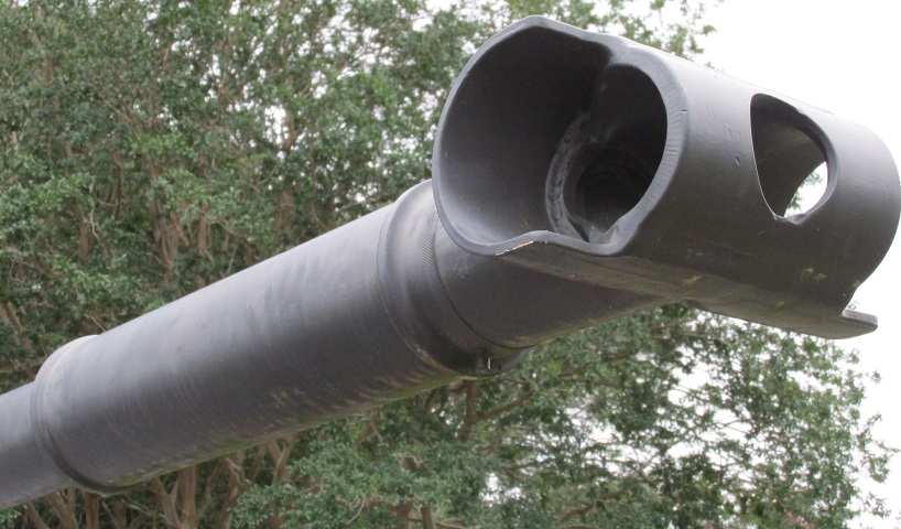
Details of the muzzle brake and bore evacuator on the 90mm gun M41 are provided here.
The auxiliary generator muffler is present on this tank.
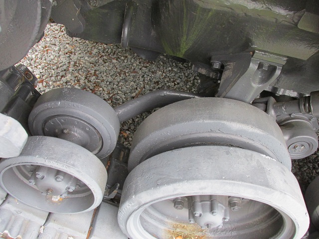
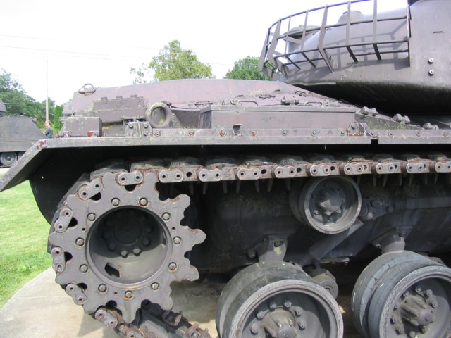
The auxiliary track tensioning idler and its swing arm are highlighted here. Note that it is mounted in a different way with a longer swing arm compared to those found on the M46 and M47 tanks. The attachment for the rear shock absorber can be seen just in front of the bump stop for the rear road wheel.
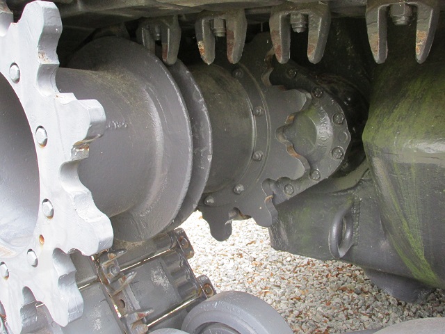
The final drives of the medium tanks from the M26 Pershing have slowly been rotating upwards, finally making it to the horizontal in the M48.
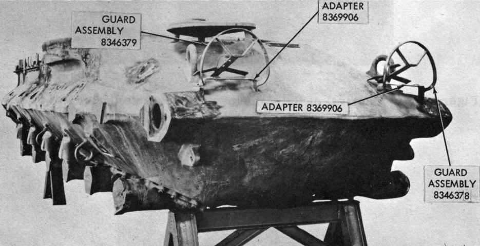
This hull has been stripped in preparation for conversion to an M48A3 Mod. B, permitting a view of the boat-like shape of the casting. (Picture from Conversion Guide Covering Modification of Tank, Combat, Full Tracked: 90-mm Gun, M48A1 to Tank, Combat, Full Tracked: 90-mm Gun, M48A3 (Mod. B) Volume 1 of 2 Hull.)
Three track return rollers instead of the five found on earlier tanks easily differentiates the M48A2. The revised headlights and brush guards; the single personnel heater exhaust over the left front fender; and the flat, angled fenders are other changes. (Picture from TM 9-7022 Operation and Organizational Maintenance: 90-mm Gun Full Tracked Combat Tank M48A2.)
The rear of the tank was redesigned in a more drastic manner, as an exhaust tunnel with rear louvres replaced the rear hull plate and decktop exhaust outlet. The infantry phone was consequently relocated to the right rear fender. (Picture from TM 9-7022 Operation and Organizational Maintenance: 90-mm Gun Full Tracked Combat Tank M48A2.)
As noted, the interphone control C-1632/VIA-4 of the intercommunication station AN/VIA-4 was mounted on the right rear fender. This allowed infantry to speak on the tank intercom, and pressing the handset switch flashed a light on the interphone control C-1633/VIA-4 in the driver's compartment. The C-1632/VIA-4 had a 10' (3m) self-coiling retractable cord. (Picture from TM 9-7022 Operation and Organizational Maintenance: 90-mm Gun Full Tracked Combat Tank M48A2.)
The revised engine exhaust and single personnel heater exhaust are easily seen from above. (Picture from TM 9-7022 Operation and Organizational Maintenance: 90-mm Gun Full Tracked Combat Tank M48A2.)
The revised engine and driving compartments can be seen in this sectionalized view. Note the forward movement of the engine air cleaners to the fighting compartment side of the bulkhead. (Picture from TM 9-7022 Operation and Organizational Maintenance: 90-mm Gun Full Tracked Combat Tank M48A2.)
A closer look at the rear louvres is provided in this picture. The square in the right rear access door was for mounting a deep wading exhaust stack. The small track tensioning idler wheel can be seen between the right drive sprocket and rear road wheel. (Picture from TM 9-7022 Operation and Organizational Maintenance: 90-mm Gun Full Tracked Combat Tank M48A2.)
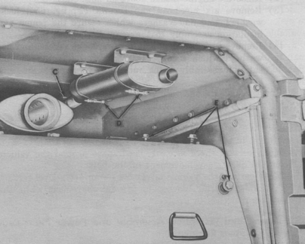
The right rear access door is open, showing the new arrangement for the right main and auxiliary engine exhausts and mufflers. C, D, and E refer to fasteners that needed to be released before the auxiliary engine muffler and powerplant rear shroud could be removed. (Picture from TM 9-7022 Operation and Organizational Maintenance: 90-mm Gun Full Tracked Combat Tank M48A2.)
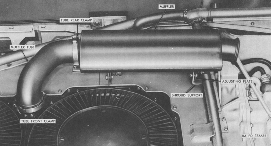
The right main engine exhaust and muffler are highlighted here with the powerplant rear shroud removed. (Picture from TM 9-7022 Operation and Organizational Maintenance: 90-mm Gun Full Tracked Combat Tank M48A2.)
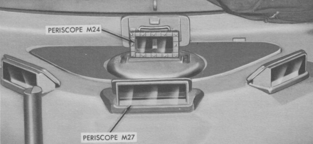
The driver's periscopes are raised on this tank, and the infrared periscope M24 is installed. The blackout service headlights projected infrared rays that were captured by the periscope and therein converted to a visible image in the binocular viewpiece. (Picture from TM 9-7022 Operation and Organizational Maintenance: 90-mm Gun Full Tracked Combat Tank M48A2.)
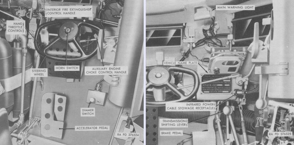
The driver's wider steering wheel is obvious when compared with earlier vehicles, and the transmission shift lever is no longer behind the steering wheel but instead to the driver's right side. (Picture from TM 9-7022 Operation and Organizational Maintenance: 90-mm Gun Full Tracked Combat Tank M48A2.)
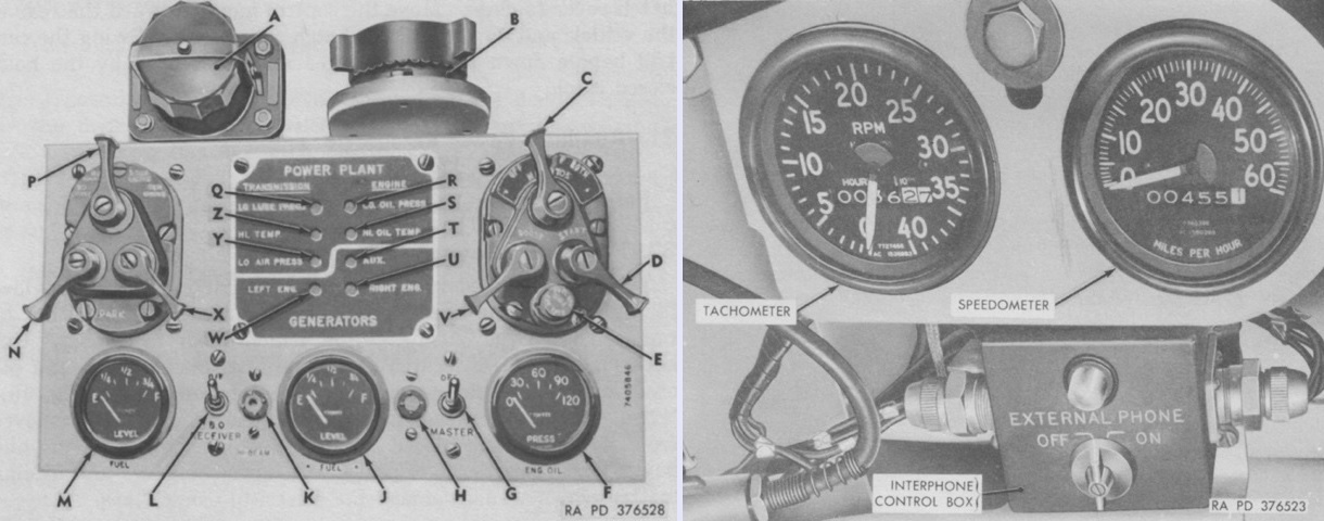
The driver's instrument panel, shared with the M48 and M48A1, is labeled in the left picture. A. Auxiliary power receptacle. B. Headlamp stowage base. C. Main engine magneto switch. D. Main engine starter switch. E. Fuel cutoff switch plunger. F. Main engine oil pressure gage. G. Master relay switch. H. Master relay switch indicator light. J. Right fuel level gage. K. High beam indicator light. L. Blackout receiver switch. M. Left fuel level gage. N. Auxiliary lighting control switch (not used). P. Main lighting control switch. Q. Transmission low oil pressure warning light. R. Engine low oil pressure warning light. S. Engine high oil temperature warning light. T. Auxiliary engine generator warning light (not used). U. Main right engine generator warning light (not used). V. Main engine booster switch. W. Main engine generator warning light. X. Main lighting control switch release lever. Y. Transmission low air pressure warning light (not used). Z. Transmission high oil temperature warning light.
Seen in the right image, the M48A2's speedometer/odometer remained to the driver's left, as in the M48 and M48A1, but it was now paired in a mounting bracket with a tachometer/hourmeter. (Picture from TM 9-7022 Operation and Organizational Maintenance: 90-mm Gun Full Tracked Combat Tank M48A2.)
The sprung, counterbalanced hatch door on the commander's cupola is shown opened. The door could be secured in three positions: fully opened, closed, or about halfway open. (Picture from TM 9-7022 Operation and Organizational Maintenance: 90-mm Gun Full Tracked Combat Tank M48A2.)
Interior room in the cupola was at a premium with the machine gun and ammunition box mounted. (Picture from TM 9-7022 Operation and Organizational Maintenance: 90-mm Gun Full Tracked Combat Tank M48A2.)
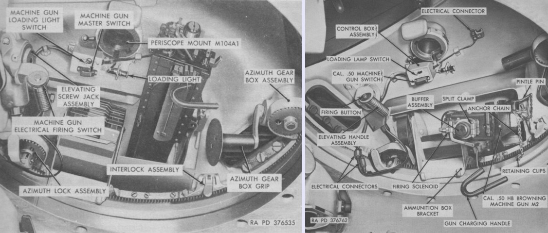
The cupola ammunition box and periscope have been removed for clarity in these views. The azimuth lock assembly was a friction lock used to prevent the cupola from rotating from a desired position. The interlock assembly was used to align the cupola with the 90mm gun so that the commander could designate targets for the gunner. When the cupola was properly aligned and the interlock handle was depressed, a pin was inserted into a hole in the mount ring gear. After the interlock was secured, the azimuth lock was engaged to prevent damage to the interlock from rotation of the cupola. (Picture from TM 9-7022 Operation and Organizational Maintenance: 90-mm Gun Full Tracked Combat Tank M48A2.)
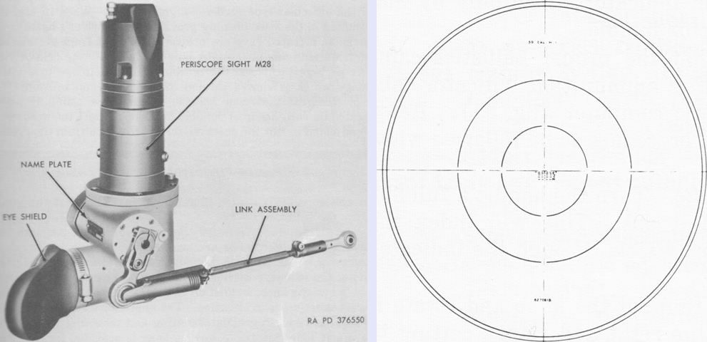
The cupola's 1.5x monocular periscope sight M28 is seen on the left along with the link assembly 8201896 that connected the periscope to the gun cradle casting. It had a 48° field of view, and the reticle used is sketched on the right. (Picture from TM 9-7022 Operation and Organizational Maintenance: 90-mm Gun Full Tracked Combat Tank M48A2.)

The commander's revised control handle is shown here. When squeezed, an actuator on the opposite side of the handle released a magnetic brake in the traversing gear box assembly and activated the solenoid-operated override control spool in the gunner's control assembly, thereby transferring turret and gun control to the commander. The upper rod coming forward from the commander's handle assembly was the elevating connecting rod, while the lower was the traversing connecting rod. (Picture from TM 9-7022 Operation and Organizational Maintenance: 90-mm Gun Full Tracked Combat Tank M48A2.)
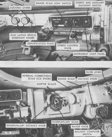
Controls on the stereoscopic rangefinder M13A1 are labeled in this image. The rangefinder was used to determine target distances from 500-4,800 yards (460-4,400m) away. (Picture from TM 9-7022 Operation and Organizational Maintenance: 90-mm Gun Full Tracked Combat Tank M48A2.)
The rangefinder's left-side mounting bracket assembly in the turret wall is shown here. (Picture from TM 9-7022 Operation and Organizational Maintenance: 90-mm Gun Full Tracked Combat Tank M48A2.)
The revised controls for the gunner are labeled. The entire control assembly now rotated clockwise or counterclockwise to traverse the turret. (Picture from TM 9-7022 Operation and Organizational Maintenance: 90-mm Gun Full Tracked Combat Tank M48A2.)
The ballistic computer M13A1 is shown from the front. It differed from the ballistic computer M13 (T31) found in the M48 in the following details: 1. New cam change access plate to accommodate a new cam puller that eased disassembly without damaging the pins. 2. New range scale light ring design that eased maintenance. 3. New bracket on superelevation mil counter which eased maintenance. 4. New circuit breaker guard that protected the toggle, as well as a circuit breaker with a stronger Bakelite toggle. 5. New stronger two-piece servo motor mounting bracket. 6. Ammo indicator detent changed to cast iron from weaker aluminum. 7. Dowel pins added to top cover to maintain alignment and prevent shaft bending. 8. Servo roller shaft changed to stainless steel from brass. 9. Superelevation handcrank shaft shoulder restored to prevent shaft hangup by adding a collar. 10. Superelevation handcrank sleeve bearing added to prevent shaft galling. 11. New gasket on actuator assembly to prevent water leakage. 12. New housing due to new ring design and hole relocation. 13. Superelevation handcrank shear pin added to prevent gear tooth shearing. 14. Precision ground stainless pins replaced the standard pins. 15. Holes in housing for new light ring. (Picture from TM 9-1220-203-34 Field Maintenance Manual Ballistic Computers M13, M13A1, M13A1C, and M13A1D.)
The top cover has been removed from the ballistic computer M13A1, allowing a glimpse of the interior of the assembly. The M13 and M13A1 computers were 14.1" (35.8cm) long, 14.5" (36.8cm) tall excluding the input and output shafting, 11.1" (28.2cm) deep, and weighed 38.0lb (17.2kg). Maximum range limit was 4,800 yards (4,400m). (Picture from TM 9-1220-203-34 Field Maintenance Manual Ballistic Computers M13, M13A1, M13A1C, and M13A1D.)
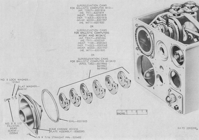
The superelevation cams are shown in this picture removed from the housing. (Picture from TM 9-1220-203-34 Field Maintenance Manual Ballistic Computers M13, M13A1, M13A1C, and M13A1D.)
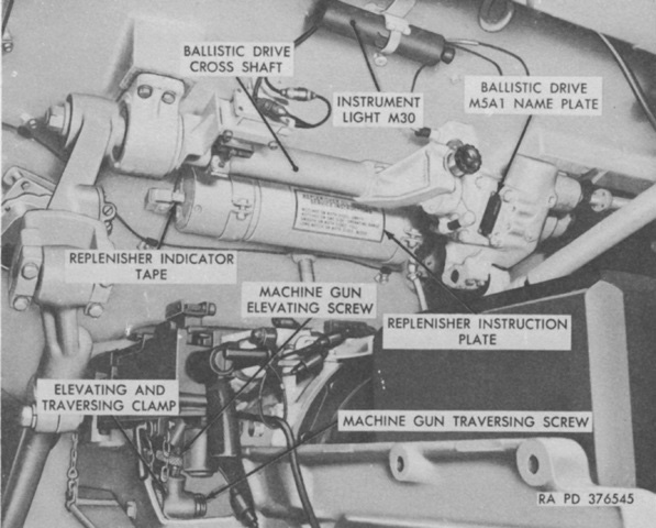
The front of the loader's position is shown here, with the coaxial machine gun to the lower left. The replenisher had an indicator to let the crew know the status of its oil level. The tape was a wound metal spring, and the level of oil in the replenisher was appropriate when shallow notches were etched into one side of the tape. When both edges were smooth, the replenisher was overfilled. When shallow notches appeared on both sides of the tape, the replenisher was dangerously low on oil or even empty. When wide notches were present on both sides, the replenisher was overfilled. (Picture from TM 9-7022 Operation and Organizational Maintenance: 90-mm Gun Full Tracked Combat Tank M48A2.)
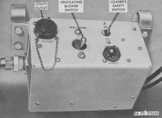
The loader's safety control box assembly featured switches for his safety and the ventilating blower, as well as a utility outlet. When the safety switch was on, the gun firing relay and the gunner's switchbox assembly were energized; the indicator light below the safety switch glowed when the safety switch was on. (Picture from TM 9-7022 Operation and Organizational Maintenance: 90-mm Gun Full Tracked Combat Tank M48A2.)
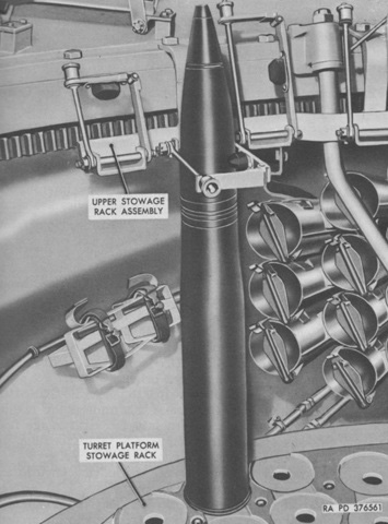
Tubular 90mm ammunition racks were installed on both sides of the driver and in the turret bustle to the left of the radio rack. A vertical ready rack was available on the turret basket floor near the loader's position. The turret on the vehicle in this picture is reversed, showing part of the left-side hull rack. (Picture from TM 9-7022 Operation and Organizational Maintenance: 90-mm Gun Full Tracked Combat Tank M48A2.)
The elevating and traversing systems are diagrammed on the left. The connecting rods from the commander's handle can be seen. Hydraulics were used for power traverse and both power and manual elevation, while manual traverse was accomplished mechanically. The power pack control assembly contained the electric motor and hydraulic pump for power operation. The pressure was stored in an accumulator until needed; when the pressure fell below 900psi (63kg/cm²), the pump was automatically activated until the pressure reached 1,225psi (86.00kg/cm²). The elevating hand pump assembly connected hydraulically to the elevating mechanism assembly.
On the right, the action of the new superelevation actuator assembly is shown. It was a mechanically actuated hydraulically operated measuring device that used data received from the ballistic computer in the form of mechanical movement of the superelevation actuator piston to meter a measured amount of pressurized hydraulic oil to the elevation assembly, thereby independently applying superelevation to the gun while the sights remained within 1 mil of the aiming point. (Picture from TM 9-7022 Operation and Organizational Maintenance: 90-mm Gun Full Tracked Combat Tank M48A2 and TM 9-2520-212-35 Ordnance, Field, and Depot Maintenance Elevating and Traversing System for Tank, Combat Full Tracked: 90-mm Gun, M48A2.)
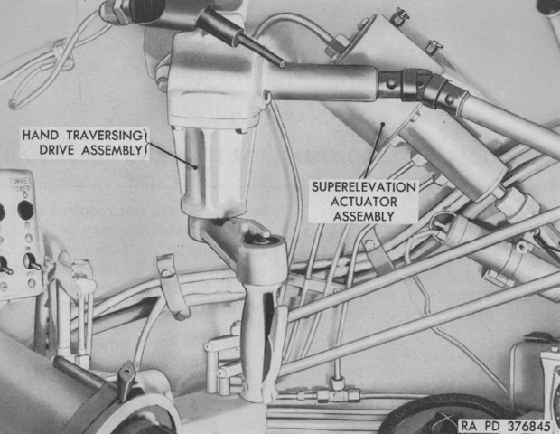
The superelevation actuator assembly was located to the gunner's right, outboard of the hand traversing drive assembly. An 8lb (4kg) average effort was required to manually traverse the turret in either direction. (Picture from TM 9-2520-212-35 Ordnance, Field, and Depot Maintenance Elevating and Traversing System for Tank, Combat Full Tracked: 90-mm Gun, M48A2.)
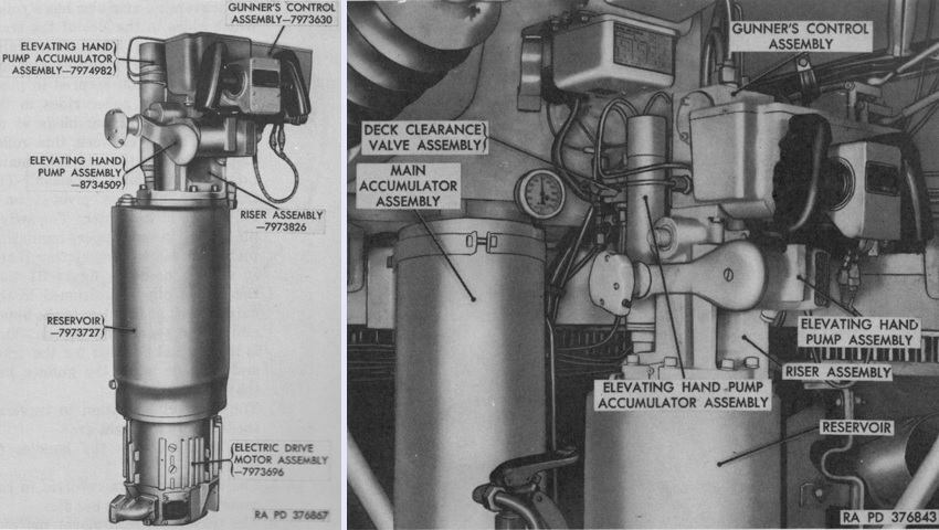
The turret power pack control assembly is seen isolated on the left and installed on the right. The 5hp A.O. Smith electric motor drove the hydraulic pump located inside the 11.25-quart (10.65L) capacity reservoir. The deck clearance valve assembly was a solenoid operated spool valve activated by gun elevation and turret traverse interference switches, and functioned to elevate the gun to 0° to clear obstructions such as fenders, the gun travel lock, and the frame and insulation assembly when the turret was traversed between 1,600 and 4,800 mils. The traverse interference switch was closed by a cam on the turret slipring box, and the elevation interference switch was closed by a cam on the ballistics drive M5A1 when the gun was at the specified elevation angle. When both interference switches were closed, the controlled oil flow from the gunner's control assembly was shut off, and oil was sent directly to the elevation mechanism assembly through the deck clearance valve. The elevating hand pump assembly was used to manually elevate or depress the gun, and also contained a gun firing switch. The power pack control assembly weighed 189lb (85.7kg), with the gunner's control assembly comprising 43.25lb (19.62kg) of that, the riser assembly 11.19lb (5.076kg), the elevating hand pump assembly 13.25lb (6.010kg), the shuttle valve assembly 0.26lb (0.12kg), the elevating hand pump accumulator assembly 2.25lb (1.02kg), the reservoir 17.45lb (7.915kg), and the motor 80.00lb (36.29kg). (Picture from TM 9-2520-212-35 Ordnance, Field, and Depot Maintenance Elevating and Traversing System for Tank, Combat Full Tracked: 90-mm Gun, M48A2.)
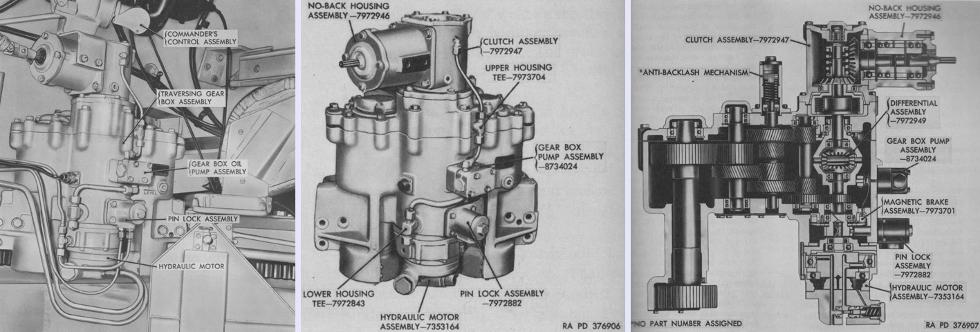
The American Gear turret traversing gear box assembly is shown installed on the left, isolated in the center, and in cross-section on the right. The gear box assembly provided mechanical output against the turret ring in order to traverse the turret. Input was supplied from the manual hand traversing drive or hydraulically from the power control assembly. Input could be taken from both the power control assembly and the hand traversing drive simultaneously. When the hydraulic power was off, the power input shaft was locked against the differential assembly by the pin lock assembly, also manufactured by American Gear, with 125psi (8.79kg/cm²) of pressure so that motion from the hand traversing assembly could not be transmitted to the power input shaft. When the power was on, such motion was prevented by hydrostatic lock. The gearbox assembly was 23" (58cm) high, 14½" (36.8cm) long, and 19" (48cm) wide, and weighed 298lb (135kg). The differential assembly weighed 4.85lb (2.20kg), the clutch 20.86lb (9.462kg), the pin lock assembly 3.01lb (1.37kg), the Warner Electric Brake and Clutch magnetic brake 1.73lb (.785kg), the Eureka Williams hydraulic motor assembly 22.80lb (10.34kg), and the American Gear gear box pump assembly 4.20lb (1.91kg). (Picture from TM 9-2520-212-35 Ordnance, Field, and Depot Maintenance Elevating and Traversing System for Tank, Combat Full Tracked: 90-mm Gun, M48A2.)
The Skardon T. Smith no-back housing assembly weighed 8.70lb (3.95kg). The hand traversing drive assembly was connected to the no-back assembly, and the no-back assembly prevented any motion from being transmitted from the traversing gear box assembly (e.g., originating from the hydraulic motor) to be transmitted to the manual input shaft. The hand traversing drive assembly also had a detent position which locked the handle assembly and prevented it from striking the gunner should the no-back assembly fail. (Picture from TM 9-2520-212-35 Ordnance, Field, and Depot Maintenance Elevating and Traversing System for Tank, Combat Full Tracked: 90-mm Gun, M48A2.)
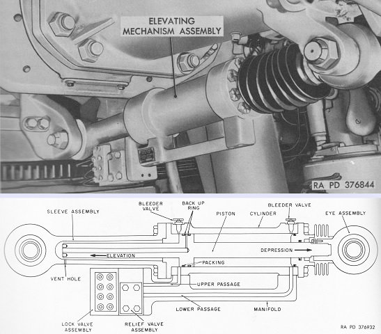
The Cadillac Gage elevating mechanism assembly is installed underneath the combination gun mount at the top and drawn in cross-section at the bottom. The sleeve assembly was secured to the turret ring, with the eye assembly attached to the combination gun mount. The lock valve and relief valve assemblies were in series with the manifold, with the lock valve assembly containing manual, superelevation, and power lock valves in the single assembly. Six ports at the front of the lock valve assembly permitted oil to flow through the relief valve assembly and manifold to the cylinder. The manual depression and elevation ports were at the top left and right, respectively, with the superelevation depression and elevation ports in the center and the power depression and elevation ports at the bottom. The relief valve dissipated internal pressures caused by external forces acting on the gun in order to prevent backpressure from occurring. The elevating mechanism assembly was 8" (20cm) high, 31" (79cm) long with the piston retracted, 4½" (11cm) wide, and weighed 69lb (31kg). (Picture from TM 9-2520-212-35 Ordnance, Field, and Depot Maintenance Elevating and Traversing System for Tank, Combat Full Tracked: 90-mm Gun, M48A2.)
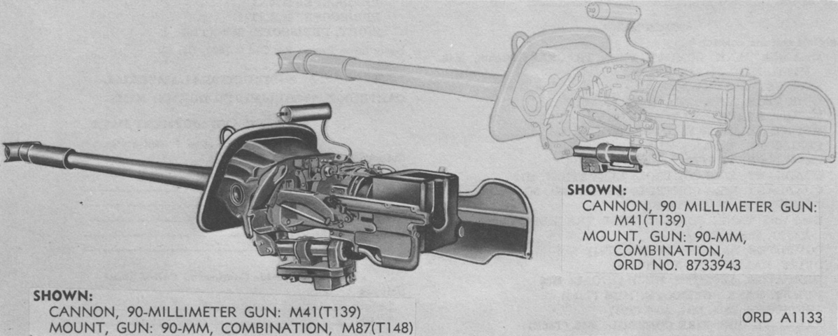
The combination gun mount ORD No. 8733943 differed from the M87 by using a modified recoil mechanism assembly and cradle assembly, and late models had the splatter guards and their attaching hardware eliminated. The 8733943 also accepted the new elevating mechanism, as shown here. (Picture from TM 9-500 C3 Data Sheets for Ordnance Type Materiel.)
A schematic of the fire control instruments and their connections is provided here. (Picture from TM 9-7022 Operation and Organizational Maintenance: 90-mm Gun Full Tracked Combat Tank M48A2.)
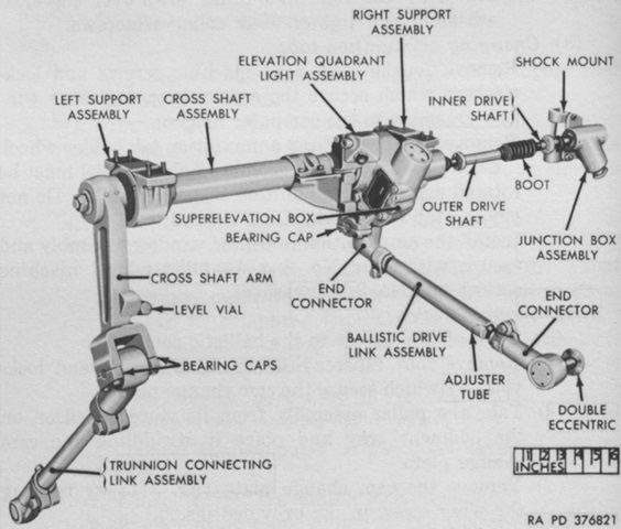
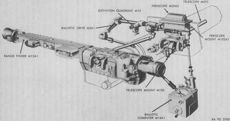
The ballistic drive M5A1 connected the main gun, the gunner's periscope M20A3 head, the the rangefinder M13A1, and the ballistic computer M13A1. As the computer calculated superelevation, its output shaft transmitted this to the ballistic drive's superelevation box. The superelevation box rotated a coupling connected to the head of the periscope M20A3 and an arm connected to the ballistic drive link, which was connected to the rangefinder. The lines of sight of the periscope and rangefinder were consequently both depressed at the same rate and for the same angular deviation. Other linkages synchronized the motion of the sighting instruments with the motion of the gun. (Picture from TM 9-7022 Operation and Organizational Maintenance: 90-mm Gun Full Tracked Combat Tank M48A2.)
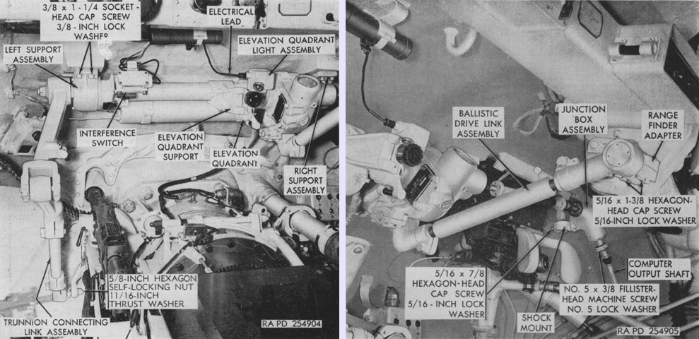
The ballistic drive M5A1 is shown installed in the turret in the above views. It was ~55" (~140cm) long, ~45" (~110cm) wide installed, and ~29½" (~74.9cm) high installed, and weighed 135lb (61.2kg). (Picture from TM 9-6191 Ordnance Field and Depot Maintenance Ballistic Drive M5A1 (T24E5).)
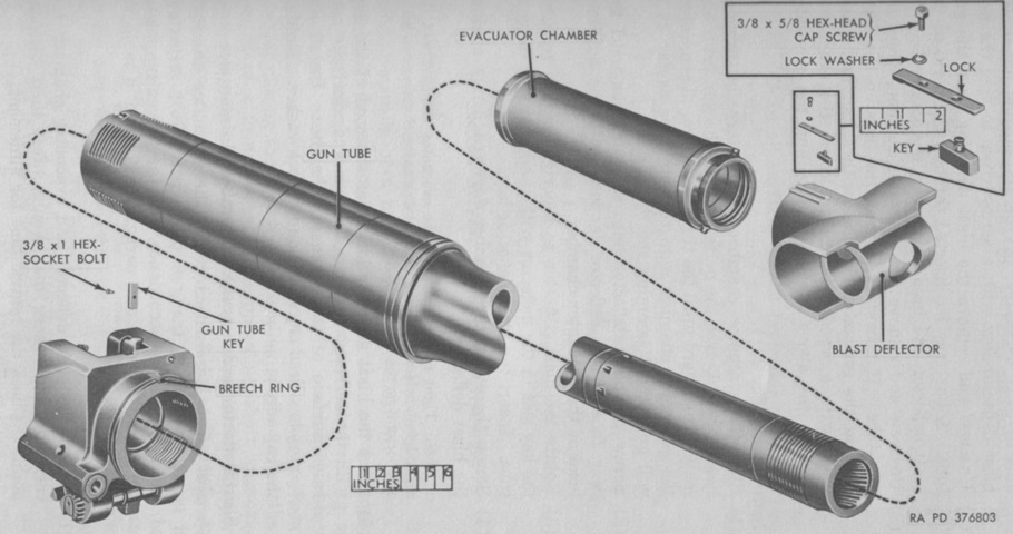
The interrupted threads that secured the gun to the breech can be seen in this exploded view. (Picture from TM 9-7022 Operation and Organizational Maintenance: 90-mm Gun Full Tracked Combat Tank M48A2.)
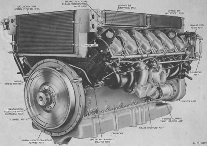
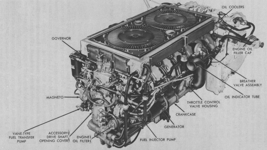
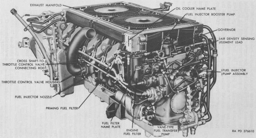
The fuel-injected AVI-1790-8 dispensed with the carburetors found on previous engines in favor of a fuel injection system, resulting in enhanced fuel distribution and resistance to icing, and elimination of the need to heat the mixture and a hotspot-style manifold. The oil coolers were also mounted around the top of the engine instead of vertically out to the sides. This made the engine a more compact unit and enabled larger fuel tanks to be mounted in the empty space thus created in the engine compartment. The engine was 72.67" (184.6cm) long, 47.80" (121.4cm) wide without the oil filter extension pipe, 61.92" (157.3cm) wide with the oil filter extension pipe, and 42.71" (108.5cm) tall, and dry weight was 2,975lb (1,349kg) with accessories and flywheel. Compression ratio was 6.35:1. The flywheel end seen here was considered the rear, while right and left were determined by looking at the engine from the accessory end toward the flywheel end. (Picture from TM 9-2805-206-35.)
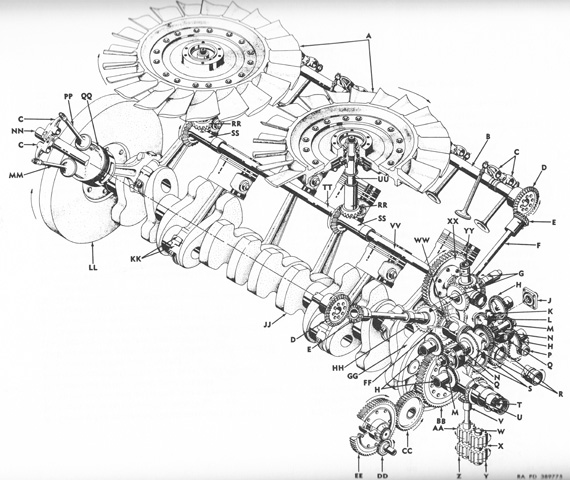
The gear train and major components of the engine are sketched. A. Cooling fan rotor and clutch assembly. B. Right camshaft assembly. C. Valve rocker and adjusting screw assembly. D. Camshaft driven bevel gear. E. Upper camshaft drive quill bevel gear. F. Camshaft drive quill. G. Fuel injector pump driven shaftgear. H. Magneto drive driven gear. J. Tachometer drive adapter assembly. K. Tachometer drive driven idler shaftgear. L. Tachometer drive driven shaftgear. M. Magneto drive gear assembly. N. Magneto and spark advance governor drive shaft. P. Generator drive shaft assembly. Q. Spark advance governor assembly. R. Spark advance governor drive bevel gear. S. Generator drive idler gear assembly. T. Accessory drive crankshaft extension shaft. U. Oil pump drive bevel gear. V. Oil pump driven bevel gear. W. Oil pump driven impeller idler shaft. X. Oil scavenge pump driven impeller. Y. Oil pressure pump driven impeller. Z. Oil pressure pump drive impeller w/integral shaft. AA. Oil scavenge pump drive impeller. BB. Accessory drive gear and shaft assembly. CC. Starter idler gear assembly. DD. Fuel pump drive gear. EE. Starter and fuel pump drive gear and hub assembly. FF. Accessory drive driven shaftgear. GG. Crankshaft damper counterweight. HH. Lower camshaft drive quill bevel shaftgear. JJ. Crankshaft assembly. KK. Connecting rod and cap assembly. LL. Flywheel. MM. Intake valve. NN. Left camshaft assembly. PP. Exhaust valve. QQ. Piston. RR. Fan drive driven bevel shaftgear. SS. Fan drive bevel shaftgear. TT. Rear horizontal fan drive shaft. UU. Vertical fan drive shaft. VV. Front horizontal fan drive shaft assembly. WW. Camshaft drive bevel gear. XX. Fuel injector pump drive shaftgear assembly. YY. Governor drive bevel gear. (Picture from TM 9-2805-206-35.)
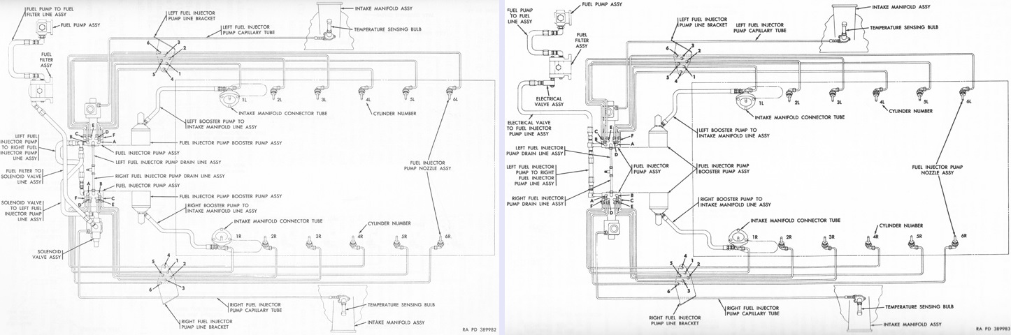
A schematic of the fuel system of an early engine is on the left, and can be compared with that for a late engine on the right. On late engines, the fuel solenoid valve was moved from the right fuel injector pump to the outlet of the fuel filter. Gasoline from the vehicle fuel tanks was supplied to the engine vane-type fuel pump assembly at a minimum of 5psi (.35kg/cm²), where the pressure was increased to a minimum of 20psi (1.4kg/cm²). From there the gasoline flowed through the fuel filter and fuel solenoid valve to the fuel injector pumps. (Picture from TM 9-2805-206-35.)
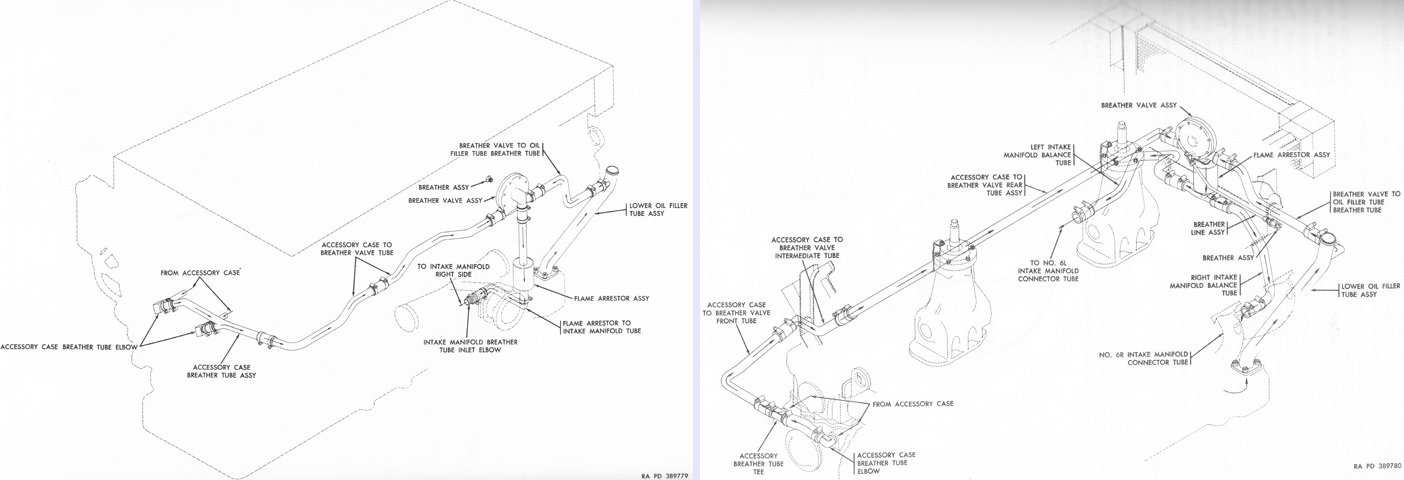
The early crankcase breather system on the left can be contrasted to the later version on the right. The breather valve tubing and flame arrestor in late engines were moved to between the cylinder banks in the engine V. (Picture from TM 9-2805-206-35.)
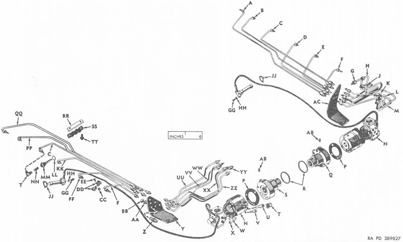
The fuel injector pumps, lines, and brackets are the subject of this exploded diagram. A. No. 6R fuel injector pump line assembly. B. No. 5R fuel injector pump line assembly. C. No. 4R and 4L fuel injector pump line assembly. D. No. 3R fuel injector pump line assembly. E. No. 2R fuel injector pump line assembly. F. No. 1R and 1L fuel injector pump line assembly. G. No. 5R fuel injector pump outlet line assembly. H. No. 2R fuel injector pump outlet line assembly. J. No. 3R fuel injector pump outlet line assembly. K. No. 6R fuel injector pump outlet line assembly. L. No. 1R fuel injector pump outlet line assembly. M. No. 4R fuel injector pump outlet line assembly. N. Fuel injector pump assembly. P. Fuel injector pump mounting gasket. Q. Right fuel injector pump adapter. R. 2¼ id, 2½ od, ⅛ thk "O" ring packing. S. Left fuel injector pump adapter. T. ¼ tube, ⅛ pipe, 90° elbow. U. ⅛ pipe coupling (long). V. ⅛ pipe coupling (short). W. 21/64 id, 9/16 od, 1/16 thk flat washer. X. 5/16 self-locking nut. Y. Left fuel injector pump lines bracket. Z. ¼ compression tube union. AA. ½ lock washer. BB. ½ union nut. CC. No. 10 self-locking nut. DD. ¼ id cushioned closed clip. EE. No. 10-32 x 5/16 machine screw. FF. No. 2L fuel injector pump line assembly. GG. No. 10-24 x ¾ machine screw. HH. 13/64 id, 7/16 od, 1/16 thk flat washer. JJ. Temperature bulb mounting gasket. KK. No. 3L fuel injector pump line assembly. LL. 49/64 id, 1 od, 1/16 thk plain washer. MM. Fuel injector pump nozzle assembly. NN. Fuel injector nozzle filter assembly. PP. No. 5L fuel injector pump line assembly. QQ. No. 6L fuel injector pump line assembly. RR. Fuel injector pump lines plate. SS. Fuel injector pump lines clamp. TT. No. 10-32 x ⅜ assembled washer screw. UU. No. 1L fuel injector pump outlet line assembly. VV. No. 6L fuel injector pump outlet line assembly. XX. No. 4L fuel injector pump outlet line assembly. YY. No. 5L fuel injector pump outlet line assembly. ZZ. No. 3L fuel injector pump outlet line assembly. AB. 1/16 pipe plug. AC. Right fuel injector pump lines bracket. (Picture from TM 9-2805-206-35.)
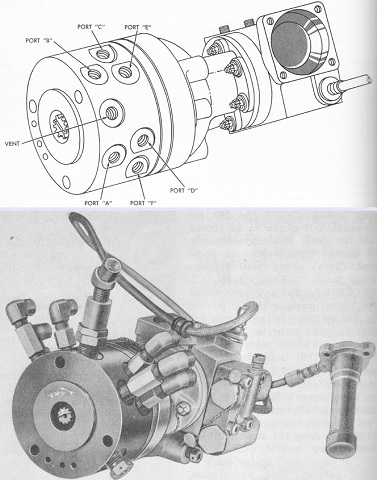
The Simmonds model SU-15G3 fuel injector pump was a speed density metering unit that measured the air density in the intake manifolds and metered the fuel to the combustion chambers in accordance with the mass air flow. The three main variables accounted for by the pump were engine speed, air pressure, and air temperature in the intake manifold. The spill vent, which had a constant bleed rate of 12 gallons/hour (45L/hour) during operation, used pressure induced by the vane-type fuel pump assembly to bleed off and return excess fuel vapor to the fuel tanks. (Picture from TM 9-2805-206-35.)
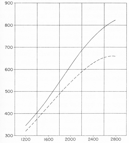
The full-throttle power curves for an engine equipped with cooling fans, air cleaners, and mufflers are plotted for gross performance (solid line) and net performance after accessory losses (dashed line) with horsepower on the Y axis and engine rpm on the X axis. The data was corrected to 29.92 inHG (1 atm) dry barometric pressure and 60°F (16°C). (Picture from TM 9-2805-206-35.)
The engine is shown here attached to the transmission. The cylinders were numbered 1 to 6 on each side starting at the accessory end. Firing order was 1R, 2L, 5R, 4L, 3R, 1L, 6R, 5L, 2R, 3L, 4R, 6L. (Picture from TM 9-7022 Operation and Organizational Maintenance: 90-mm Gun Full Tracked Combat Tank M48A2.)
Components of the new fuel system are seen again in this picture. (Picture from TM 9-7022 Operation and Organizational Maintenance: 90-mm Gun Full Tracked Combat Tank M48A2.)
Two fuel tanks were installed on each side of the engine, with the left tanks in left image and the right tanks on the right. The smaller right-side tanks held 135 gallons (511L), while the larger left-side tanks stored 190 gallons (720L) of fuel. Pumps in the lower tanks on each side took the fuel to a vane-type fuel transfer pump on the engine. Torsion bars for the road wheels and rear track tensioning idler wheels can be seen crisscrossing the hull floor. (Picture from TM 9-7022 Operation and Organizational Maintenance: 90-mm Gun Full Tracked Combat Tank M48A2.)
The batteries are seen here through the turret floor.. (Picture from TM 9-7022 Operation and Organizational Maintenance: 90-mm Gun Full Tracked Combat Tank M48A2.)
Some changes to the suspension can be gleaned from this sketch. The double bump stop on the leading road wheel is shown, and the second and fourth track return rollers have been eliminated. Friction snubbers, which were cylinders inside of which was a piston covered with brake lining, replaced the earlier hydraulic shock absorbers. (Picture from TM 9-7022 Operation and Organizational Maintenance: 90-mm Gun Full Tracked Combat Tank M48A2.)
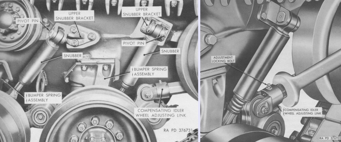
The compensating idler wheel adjusting link was changed to an internal screw design, and the method of adjusting the track tension is shown on the right. After the adjustment locking bolt was loosened, the compensating idler wheel adjusting link was turned to move the wheel forward or backward to achieve the recommended tension. (Picture from TM 9-7022 Operation and Organizational Maintenance: 90-mm Gun Full Tracked Combat Tank M48A2.)
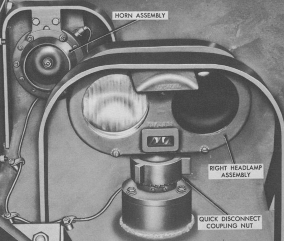
The right headlamp assembly and brush guard are shown in this picture. The headlamp assemblies were changed so that they were the same on both sides of the tank. The vibrator-type horn was mounted behind the right headlamp assembly. (Picture from TM 9-7022 Operation and Organizational Maintenance: 90-mm Gun Full Tracked Combat Tank M48A2.)
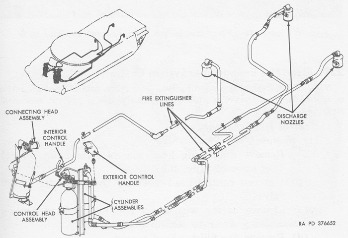
The positioning of the fixed fire extinguisher cylinders was altered from earlier tanks, with two now on the left and the single cylinder on the right. The portable extinguisher was mounted on the turret platform to the left of the gunner's seat. (Picture from TM 9-7022 Operation and Organizational Maintenance: 90-mm Gun Full Tracked Combat Tank M48A2.)
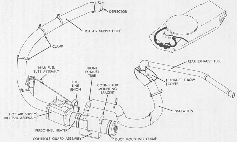
The twin heaters of earlier tanks were replaced by a single Stewart-Warner 1060D-M24 gasoline-fueled unit that served both the driving and fighting compartments. Its layout is sketched in this drawing. (Picture from TM 9-7022 Operation and Organizational Maintenance: 90-mm Gun Full Tracked Combat Tank M48A2.)
This M48A2C lacks the small track tensioning idler previously found between the last road wheel and drive sprocket. The most important changes were internal, however, and included a new coincidence rangefinder and other fire control system improvements. One of the rangefinder sights is visible on the top side of the turret.
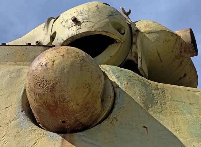
The elliptical cross-section of the tank can be seen in this view. A Y-shaped blast deflector is apparent, as are the two sighting blisters for the M17 coincidence rangefinder on the top of the turret sides. The single exhaust for the personnel heater is visible to the right of the driver's hatch, and the three periscope housings surrounding his hatch are closed. The driver's hatch itself has a mount for an infrared periscope. Just to the left of the driver's hatch is a support for when it is rotated to the open position. The large M1 commander's cupola dominates the turret's right side, and the guard for the gunner's M32 periscope is visible in front of the TC's cupola. The opening for the coaxial machine gun has been plated over on the gun shield's left side, and the larger aperture for the gunner's M97C telescope is on the other side of the 90mm gun.
The difference between the small driver's hatch in the tank above is easily contrasted with the hatch on this later model.
The new exhaust grille is obvious when the vehicle is viewed from behind. The square in the right-side door is for mounting a deep-water fording exhaust stack. The vehicle's taillights are just below the exhaust grille doors, and a towing pintle is placed in the center of the lower rear plate. The two square plates and the circular plate above the towing pintle still provide access to the transmission. The ventilator is also visible on the turret's left side, and a periscope guard rises up from the commander's cupola. The housing for the infantry telephone intercom can be seen on the right fender.
This tank lacks the track tensioning idler wheel found on the earlier Patton tanks. The number of track return rollers has also been reduced to three. The frame for the insulated exhaust tunnel is visible, and engine intake grilles line both sides of the exhaust tunnel. The friction snubber on the last road wheel is also apparent, just in front of the return roller.
From this angle, the M48A3 resembles the M48A1 whence it was derived, but the presence of fender-mounted air cleaners for its diesel engine provides positive identification. (Picture from TM 9-2350-224-10 C9.)
The air cleaners were taller than the stowage boxes remaining on the fenders. (Picture from TM 9-2350-224-10 C9.)
The M48A3 retained the infrared-reducing engine compartment design seen earlier on the M48A2 and M60. (Picture from TM 9-2350-224-10 C9.)
A top-down cross-section of the hull is sketched here. The batteries are located behind the driver. (Picture from TM 9-2350-224-10 C9.)
Another view into the hull from the turret opening shows the installed batteries. The driver's compartment is to the upper left of the image. (Picture from TM 9-2350-224-20.)
The turret interior layout is revealed in this drawing. (Picture from TM 9-2350-224-10 C9.)
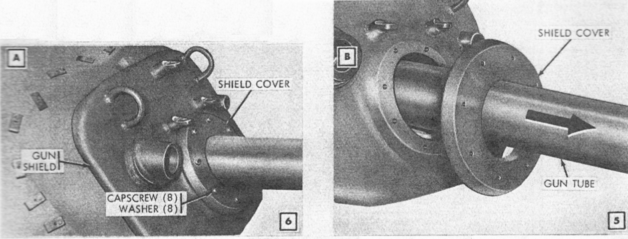
The turret's shield cover attached to the gun shield via eight capscrews and washers. (Picture from TM 9-2350-224-20.)
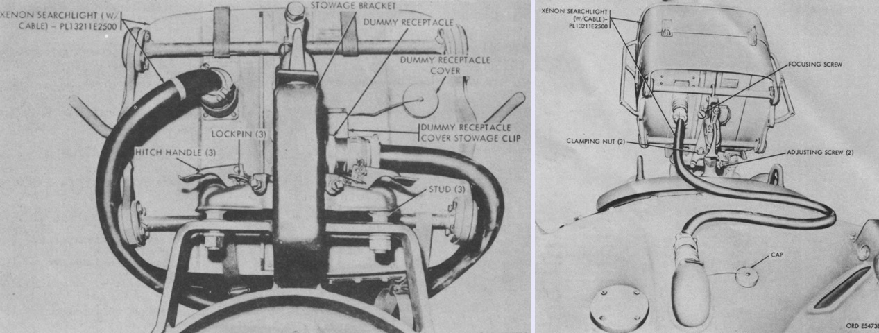
The xenon searchlight is shown on the left stowed on its bracket on the turret ventilating blower, and installed over the main gun on the right. The light provided either infrared or white light and was rated at 75 million candlepower. The light beam could produce a narrow 1.2° beam or wide 7.0° beam in either infrared or white light. When mounted, the power cable was to be looped to the right of the turret in order to provide increased protection for it. The light had an overdrive function where its intensity was increased for 15 seconds, and a blackout or standby mode allowed the lamp to operate at full brightness without emitting light from the searchlight. (Picture from TM 9-2350-224-10 C9.)
This light is mounted over the gun, but the power cable has not been attached.
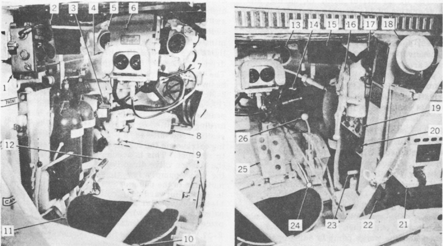
Two views of the driver's station are provided here; his infrared periscope M24 is installed, but his seat back has been removed for clarity. 1. Control box C-375/VRC. 2. Gage indicator panel. 3. Two shot fire extinguisher control. 4. Dome light (hidden). 5. Tachometer. 6. Periscope M24. 7. Steering control. 8. Brake pedal. 9. Dimmer switch. 10. Drain valve controls. 11. Seat. 12. Purge pump handle. 13. Speedometer. 14. Personnel heater. 15. Periscope M27 (3). 16. Hatch control handle. 17. Turret seal pressure gage. 18. Warning horn. 19. Master control panel. 20. Control box C 1633/VIA-4. 21. Filter unit. 22. Slave receptacles. 23. Turret seal hand pump. 24. Accelerator locking lever. 25. Accelerator pedal. 26. Transmission shift lever. (Picture from TM 9-2350-224-10 C9.)
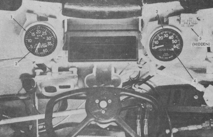
A closeup of the forward portion of the driver's compartment is shown here without the periscope M24. 1. Tachometer. 2. Engine hour meter [based on 2025rpm]. 3. Speedometer. 4. Odometer. 5. Warning light [illuminated when engine oil pressure gage read below ~13psi (.91kg/cm²), or when engine oil temperature gage read above ~245°F (~118°C) or transmission oil temperature gage read above ~285°F (~141°C)]. (Picture from TM 9-2350-224-10 C9.)
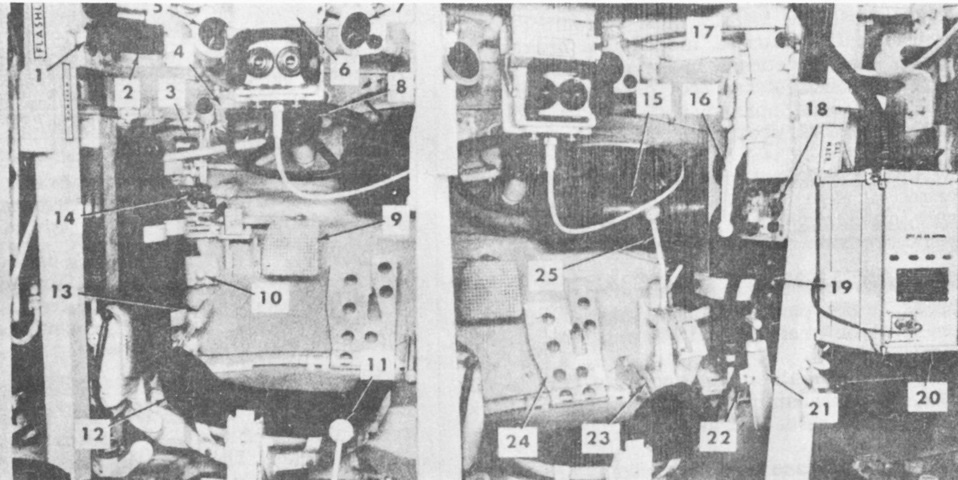
A late-production tank's driver's compartment can be contrasted. 1. Gage indicator panel. 2. Periscope M27 (3). 3. Two shot fire extinguisher control. 4. Dome light. 5. Tachometer. 6. Periscope M24. 7. Speedometer. 8. Steering control. 9. Brake pedal. 10. Dimmer switch. 11. Drain valve controls. 12. Seat. 13. Purge pump handle. 14. Hydraulic brake pressure gage. 15. Personnel heater. 16. Hatch control handle. 17. Turret seal pressure gage. 18. Driver's master control panel. 19. Inter communications control box. 20. Filter unit. 21. Turret seal hand pump. 22. Slave receptacles (hidden). 23. Accelerator locking lever. 24. Accelerator pedal. 25. Transmission shift lever. (Picture from TM 9-2350-224-10 C9.)
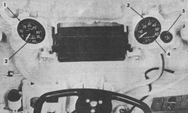
The front of a late-production driver's position is highlighted. 1. Tachometer. 2. Engine hour meter. 3. Speedometer. 4. Odometer. 5. Warning light. (Picture from TM 9-2350-224-10 C9.)
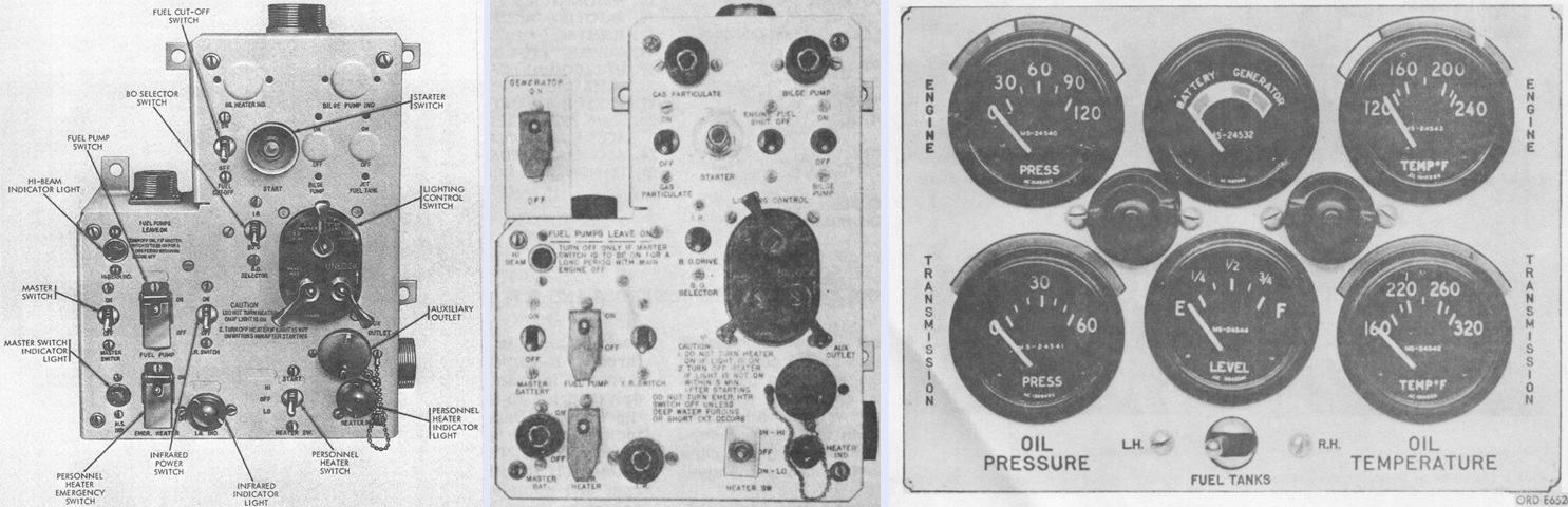
Early and late driver's master control panels are labeled on the left and center, respectively. The Generator on-off switch enabled the generator blower motor to be disabled during fording operations. The driver's gage indicator panel is illustrated on the right. (Picture from TM 9-2350-224-20 and TM 9-2350-224-10 C9.)
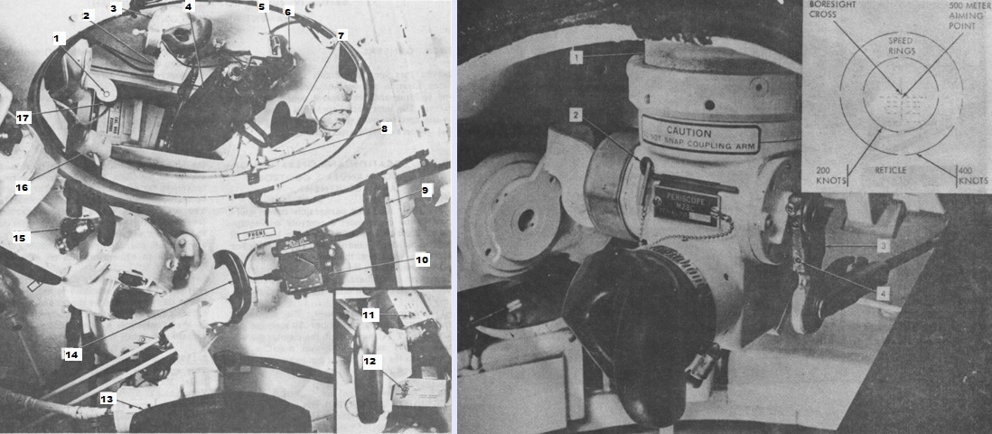
The commander's position and cupola interior can be seen on the left. 1. Gun firing trigger (switch). 2. Periscope M28C. 3. Periscope mount M104. 4. Cal. .50 machine gun M2, HB, TT. 5. Gun firing safety switch. 6. Instrument light M50. 7. Traversing handle. 8. Cupola interlock. 9. Backrest. 10. Commander's-gunner's interphone control box C-375/VRC. 11. Air purifier switch 12. Cupola electrical power control. 13. Commander's seat. 14. Commander's power control handle. 15. Rangefinder M17B1C. 16. Azimuth lock. 17. Elevating handle.
On the right, the periscope M28C is shown mounted in the cupola, with its reticle sketched in the inset. It was a 1.5x magnification device with a 48° field of view. 1. Periscope mount M104. 2. Adjusting wrench. 3. Elevation adjustment arm. 4. Elevation adjustment setscrews. (Picture from TM 9-2350-224-10 C9.)
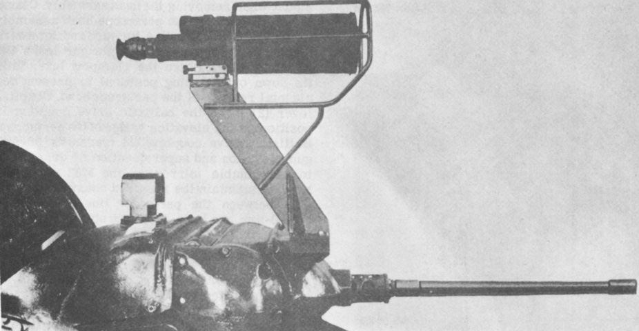
A crew served weapons night vision sight could be mounted at the commander's cupola for use with the xenon searchlight. (Picture from TM 9-2350-224-10 C9.)
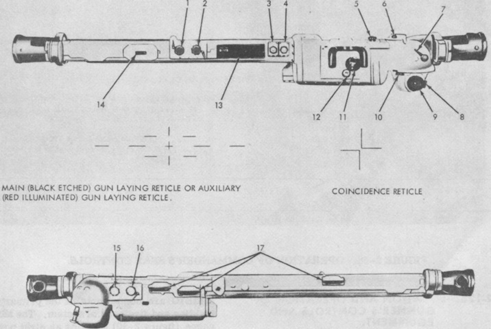
The coincidence rangefinder M17B1C was easier for a portion of the population to use, as it did not require the visual acuity of earlier stereoscopic rangefinders. The commander used vertical and horizontal adjustment knobs to move the left target "ghost" image until it was in complete coincidence with the right "actual" image; the range could then be read in the range scale window. 1. Main deflection boresight knob. 2. Main elevation boresight knob. 3. Vertical adjustment knob. 4. Horizontal adjustment knob. 5. ICS knob. 6. Range scale. 7. Filter lever. 8. Ballistic computer switch. 9. Range knob. 10. Halving knob. 11. Eyepiece. 12. Occluder knob. 13. Instrument light panel. 14. Spare lamp box. 15. Auxiliary elevation boresight knob. 16. Auxiliary deflection boresight knob. 17. Lamp assemblies. (Picture from TM 9-2350-224-10 C9.)
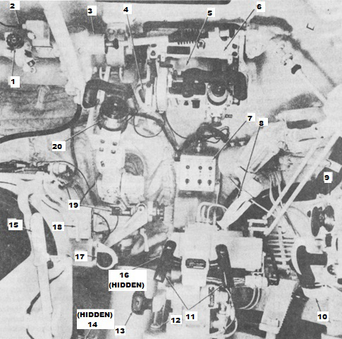
The gunner's position is shown here. 1. Fire control (elevation) quadrant M13B1. 2. Instrument light M30 connector. 3. Ballistic drive. 4. Dome light. 5. Periscope M31. 6. Periscope mount M115. 7. Gunner's switch box. 8. Manual traversing handle. 9. Ballistic computer M13B1C. 10. Azimuth indicator M28A1. 11. Gunner's power control handles. 12. Oil level gage. 13. Manual elevating handle. 14. Gas particulate filter unit. 15. Breech operating handle. 16. Accumulator pressure gage. 17. Light source control. 18. Gun hand firing lever. 19. Telescope mount M114. 20. Telescope M105. (Picture from TM 9-2350-224-10 C9.)
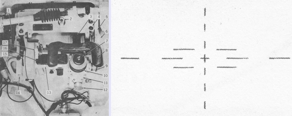
The gunner's periscope M31 had both 8x and 1x optical systems. The 8x system had an 8° field of view, while that of the 1x window was 32°32' horizontal and 5°48' vertical. The reticle for the 8x system is sketched on the right. 1. Ballistic drive coupling lever. 2. Latch. 3. Catch. 4. Periscope mount M115. 5. Locking handle. 6. Release button. 7. Eyepiece (8x). 8. Headrest. 9. Deflection boresight knob (8x). 10. Diopter scale. 11. Body assembly. 12. Elevation boresight knob (8x). 13. Head assembly. 14. Ballistic shield operating handle. 15. Release button. 16. Observation window (1x). 17. Wing nut. (Picture from TM 9-2350-224-10 C9.)
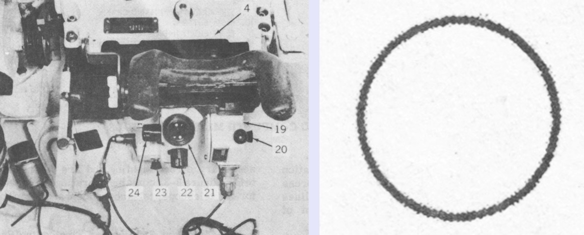
The infinity sight M44C, seen here with the periscope removed for clarity, could be installed for use with the coaxial machine gun. Its simple circular reticle is on the right. 4. Periscope mount M115. 19. Light source control. 20. Rheostat knob. 21. Infinity sight M44C. 22. Elevation boresight knob. 23. Rheostat knob. 24. Deflection boresight knob. (Picture from TM 9-2350-224-10 C9.)
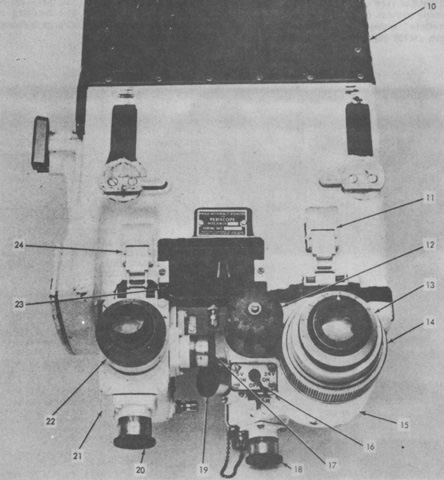
The gunner's periscope M32 contained both daylight and infrared bodies and could be used in place of the daylight-only M31. This permitted 24-hour observation when used with the xenon searchlight. Both the daylight and infrared bodies were 8x magnification with 8°0' fields of view, while the unity window had a horizontal field of view of 32°32' and vertical of 5°48'. The infinity sight 863466 was used with the coaxial machine gun. The sight reticles were similar to those of the periscope M31 and infinity sight M44C. 10. Head assembly. 11. Body latches (IR). 12. Power pack cap. 13. Diopter ring (IR). 14. Focusing ring. 15. IR body. 16. IR power switch. 17. Deflection boresight knob (daylight). 18. Elevation boresight knob (IR). 19. Deflection boresight knob (IR). 20. Elevation boresight knob (daylight). 21. Daylight body. 22. Diopter ring (daylight). 23. Unity body window. 24. Body latches (daylight). (Picture from TM 9-2350-224-10 C9.)
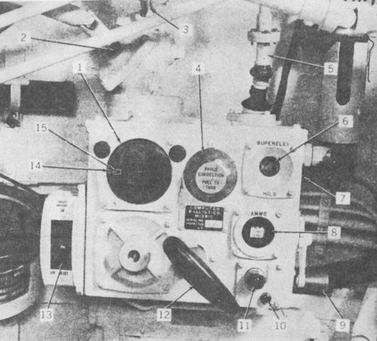
Controls for the ballistic computer M13B1C are labeled. 1. Range scale. 2. Superelevation actuator shaft. 3. Superelevation output shaft. 4. Range correction knob. 5. Range input shaft. 6. Superelevation mil counter. 7. Rheostat knob. 8. Ammunition indicator. 9. Superelevation hand crank. 10. Reset button. 11. Reset light indicator. 12. Ammunition selector handle. 13. Circuit breaker. 14. Outer (superelevation) pointer. 15. Inner (range) pointer. (Picture from TM 9-2350-224-10 C9.)

The gunner's 8x telescope M105 had a 7.5° field of view, and could be changed between reticles for T300E56 HEAT-T and M318A1 AP-T ammunition, as seen at the right. 1. Hanger. 2. Headrest adjusting knob. 3. Lead lamp. 4. Diopter ring. 5. Reticle selector lever. 6. Deflection boresight knob. 7. Deflection locking lever. 8. Elevation locking lever. 9. Elevation boresight knob. 10. Light source control. 11. Telescope mount M114. 12. Telescope M105. 13. Eyepiece. 14. Headrest. (Picture from TM 9-2350-224-10 C9.)
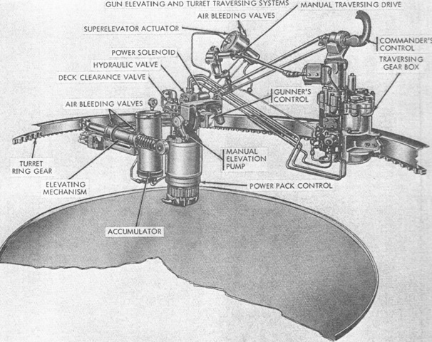
The turret elevation and traversing system is illustrated in this diagram. Manual traverse was performed mechanically, while manual elevation as well as powered traverse and elevation were all hydraulically-operated. (Picture from TM 9-2350-224-20.)
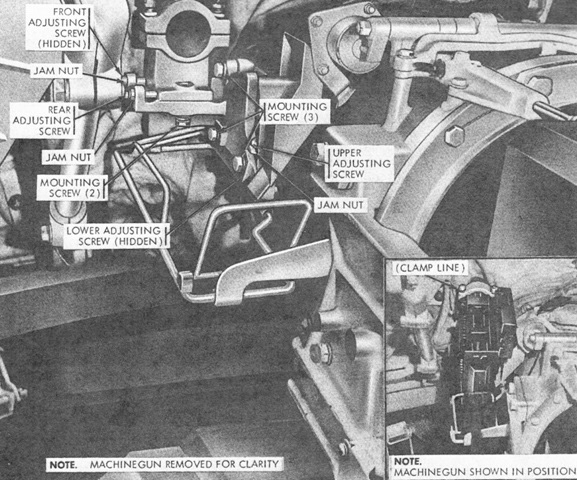
The mount and adjustments for the coaxial machine gun are labeled here with the gun removed. The gun can be seen mounted in the inset. (Picture from TM 9-2350-224-20.)
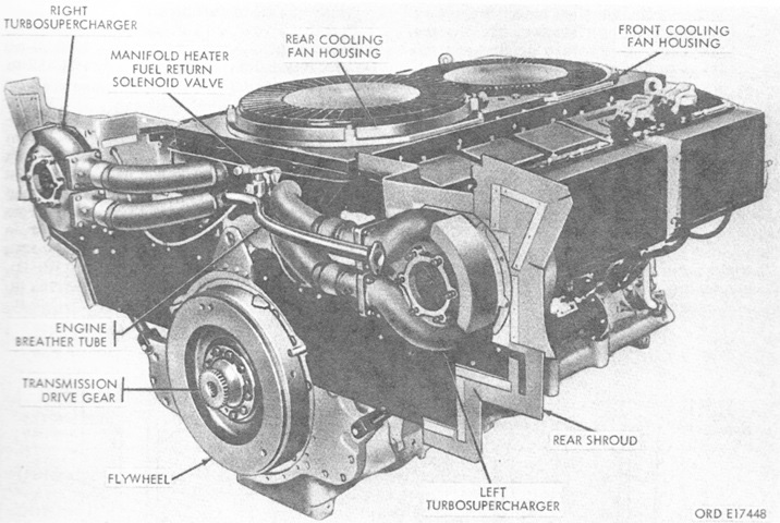
The left rear of the AVDS-1790-2 engine is shown here. The engine was 75.25" (191.1cm) long, 87.75" (222.9cm) wide including the turbosuperchargers and shroud, 45.50" (115.6cm) tall, and weighed 4,527lb (2,053kg) dry with accessories. (Picture from TM 9-2350-224-20.)
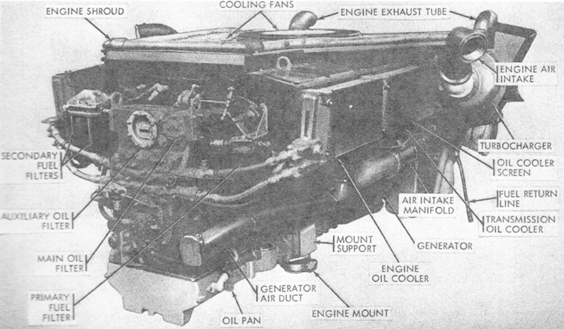
The The right front of the engine is labeled in this image. Bore and stroke remained 5.750" (14.61cm) for a displacement of 1,790in³ (29.3L), and compression ratio was 16:1. (Picture from TM 9-2350-224-20.)
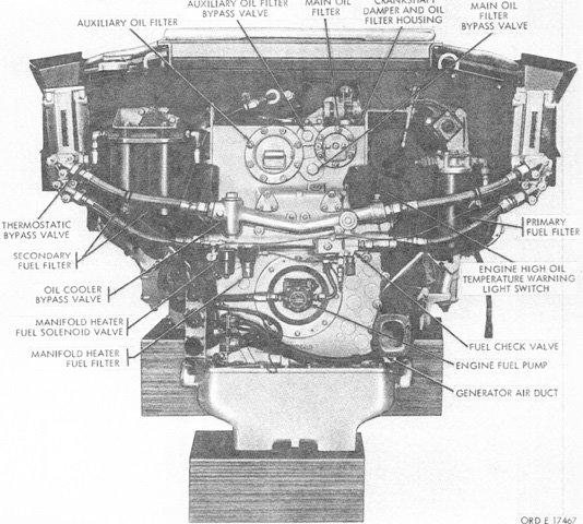
The engine is shown here from the front. (Picture from TM 9-2350-224-20.)
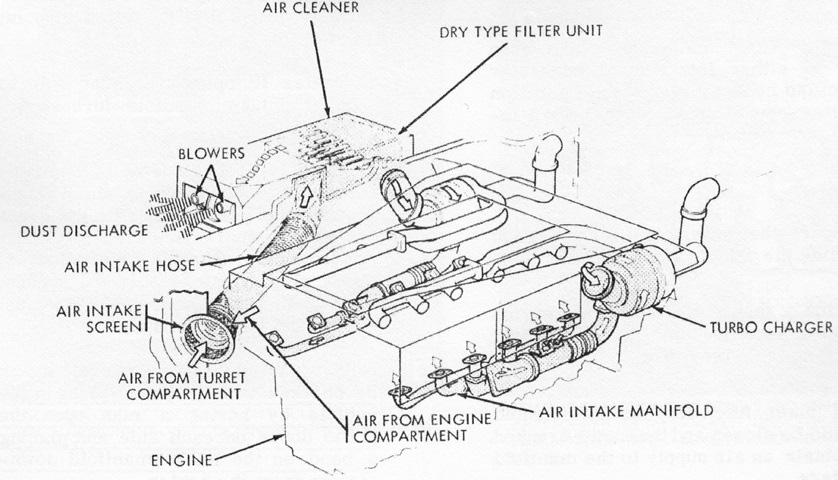
The path of airflow to the engine via the fender-mounted air cleaners is diagrammed here. (Picture from TM 9-2350-224-20.)
The right front of the CD-850-6 transmission is shown in this picture. It was 42" (110cm) tall over the oil filler tube, 53.5" (136cm) wide between the mounting pads, 30" (76cm) long, and weighed 3,025lb (1,372kg) dry. (Picture from TM 9-2350-224-20.)
The transmission is shown here from the right rear. Overall gear ratios were 1.16:1 input, 3.47:1 low range, 1.25:1 high range, and 4.90:1 reverse range. Maximum converter multiplication was 3.6:1. (Picture from TM 9-2350-224-20.)
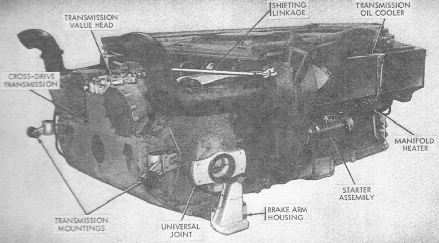
The powerplant has been assembled in this view. (Picture from TM 9-2350-224-20.)
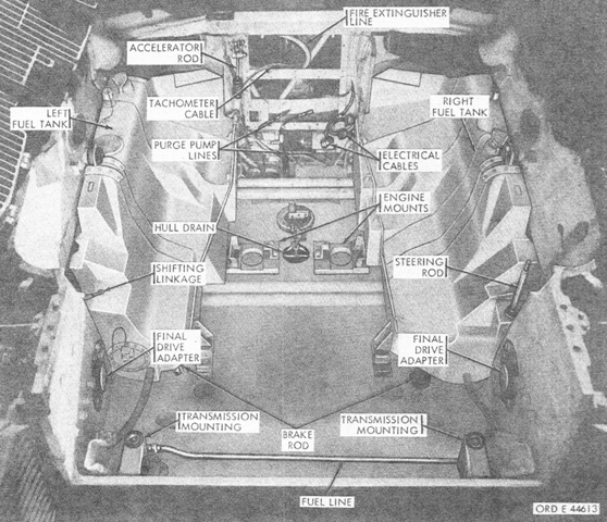
The engine compartment is shown with the powerplant removed. (Picture from TM 9-2350-224-20.)
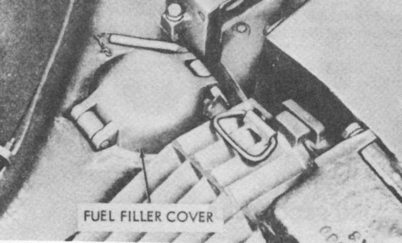
In contrast to the gasoline-engined tanks, which had a fuel filler on each side of the hull to refill the fuel tanks on their respective sides, the M48A3 had a single fuel filler on the right side that was used to fill either the tanks on both sides or only the tank on the right side after the left-side tank was isolated. (Picture from TM 9-2350-224-10 C9.)
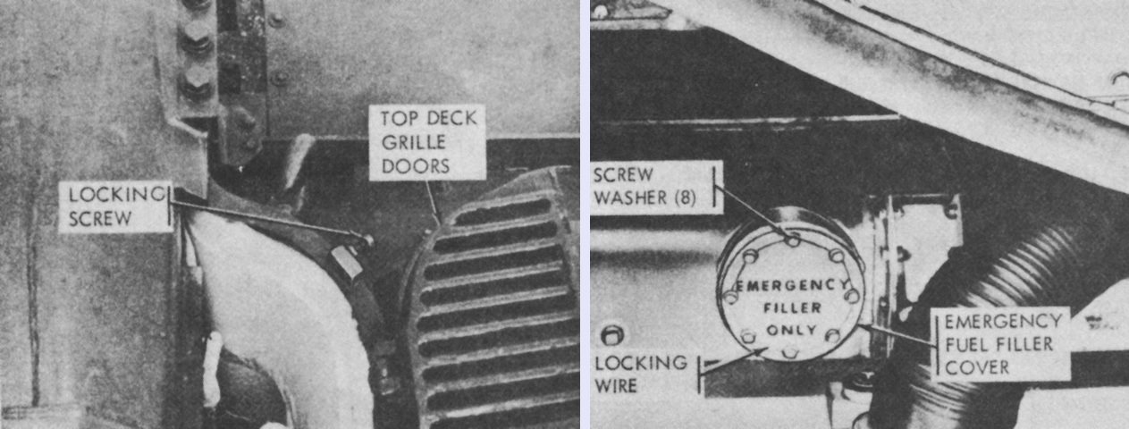
An emergency fuel filler was present on the opposite side of the hull, however. To access this filler, it was necessary to first loosen the locking screw and open the left top grille doors, as shown on the left. The emergency filler was secured by eight screws and washers and locking wire, all of which needed to be removed before the cover could be opened. The emergency filler could fill tanks on both sides, or only the left-side tank after the right tank had been isolated. When finished, the emergency filler cover was again to be secured with the eight screws and washers and lock wire. (Picture from TM 9-2350-224-10 C9.)
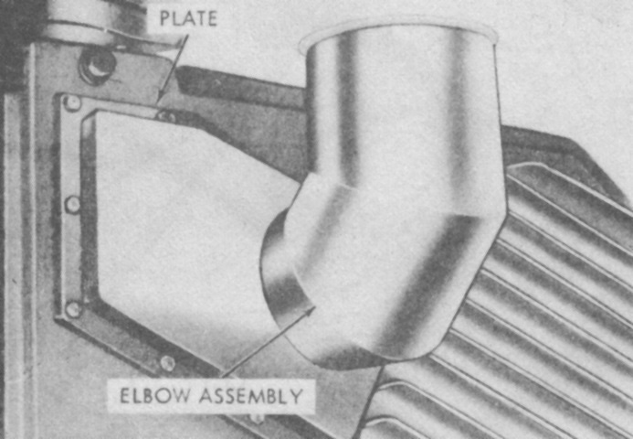
The right rear grille door had a removable plate in its upper left corner that could be exchanged for an extended exhaust stack for fording operations. The elbow assembly for the exhaust stack has been mounted on the grille door here. (Picture from TM 9-2350-224-10 C9.)
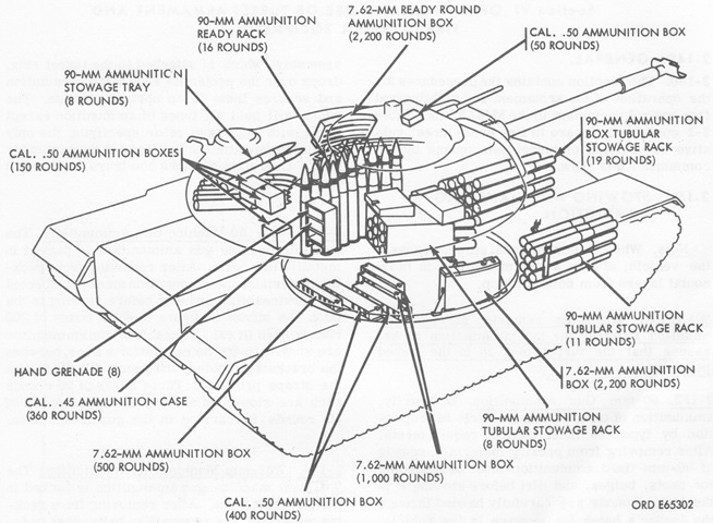
Ammunition stowage is detailed in this diagram. (Picture from TM 9-2350-224-10 C9.)
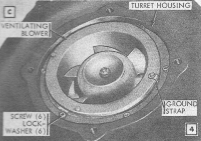
The cover has been removed from the turret ventilating blower, revealing the fan underneath. (Picture from TM 9-2350-224-20.)
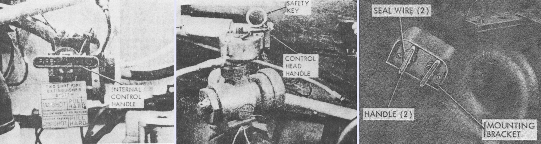
The fixed fire extinguisher system was changed to a 2-shot system. The internal control handle (left) was located to the driver's front left; pulling it out released the first shot of a single cylinder and also tripped a switch that cut fuel to the engine. If necessary, the second shot could be released by pulling the handle out again after around 20 seconds had elapsed, releasing the contents of the other two cylinders. If the internal control handle malfunctioned, the extinguishers could be discharged by removing the safety key and pulling the handle (center) on each of the two control heads. The external control on the hull front (right) had a separate handle for each shot of the system; the first shot was activated by the handle closest to the driver. Neither the control head handles nor the external controls cut fuel to the engine. (Picture from TM 9-2350-224-10 C9 and TM 9-2350-224-20.)
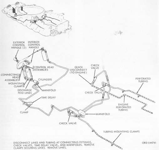
The discharge nozzles of earlier fixed fire extinguishing systems were replaced by perforated discharge tubing, with one tube on each fuel tank and one in the "V" of the engine. (Picture from TM 9-2350-224-20.)
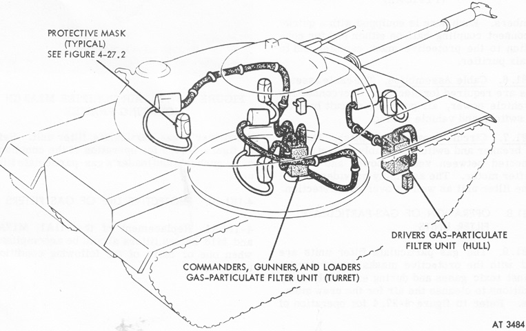
The M48A3 featured two gas-particulate filter units--one for the driver and one for the turret crew--to protect against toxic gases, biological agent attack, and extremely dusty conditions. The units would not protect against carbon monoxide, however. Each unit consisted of an air purifier M2A2, the requisite hoses and cables, and a circuit breaker and switch assembly. The air purifier M2A2 was made up of a particulate filter M13, gas filter M12A1, and an air purifier precleaner M1A1, which was a dust separator and motor blower. The hoses connected the purifiers to masks for the individual crewmen. Due to the chance of frostbite from extremely cold air, the hoses were not to be connected to the masks for the first 15-20 minutes of operation with the filter heaters on. (Picture from TM 9-2350-224-10 C9.)
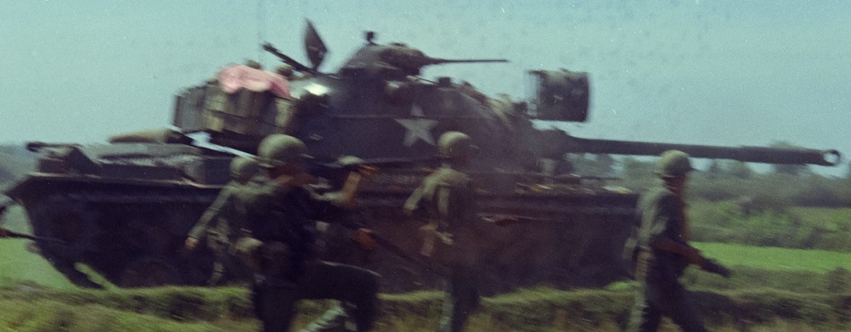
The clamshell nature of the commander's cupola can be seen in this image, where both the commander's and loader's hatches are open to the rear. These troops were part of the 3d Brigade, 1st Infantry Division and were taking part in Operation Buckskin near Laike, Republic of Vietnam. (Picture taken 8 Jan 1966; available from the National Archives.)
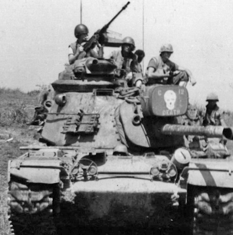
Once in action in Vietnam, some tank commanders felt that the cupola did not provide sufficient room to service the machine gun. Despite the increased exposure to enemy fire, external mounts were devised for the .50cal, as on this machine. This tank, from H Company, 2nd Battalion, 5th Marines, was fitted with the cupola vision block adapter ring. (Picture taken 20 May 1970 by Cpl G.N. Zimmerman; available from the National Archives.)
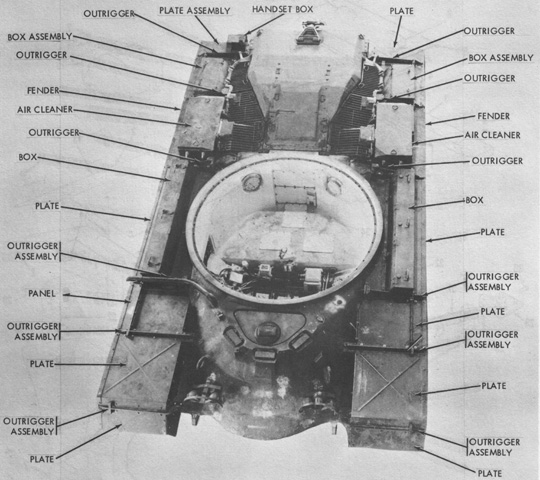
The fenders and stowage boxes are detailed here with the turret removed. The diesel engine air cleaners necessitated restructuring stowage on the fenders compared to the earlier gasoline-engined tanks. (Picture from Conversion Guide Covering Modification of Tank, Combat, Full Tracked: 90-mm Gun, M48A1 to Tank, Combat, Full Tracked: 90-mm Gun, M48A3 (Mod. B) Volume 1 of 2 Hull.)
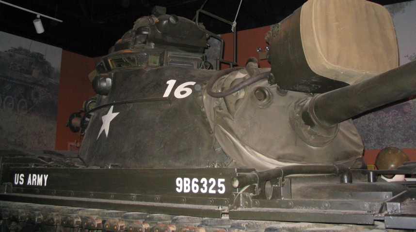
The commander's cupola on this tank sits atop the vision block adapter ring, giving the TC more room and a better all-around view. The exhaust for the M60-type personnel heater can be seen just in front of the fender stowage box. The aperture visible in the gun shield was for the gunner's direct-sight telescope.
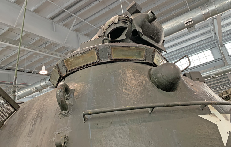
A closer look at the vision block ring is provided here. Note also the mounting pad for a night vision sight on the upper face of the machine gun shield.
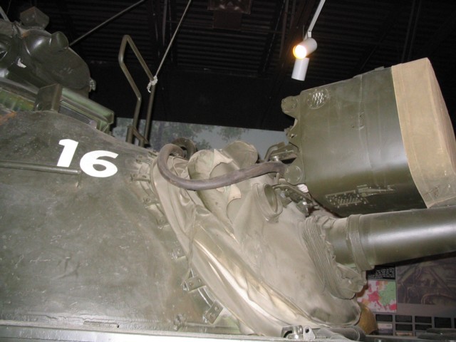
This tank is provided with a xenon searchlight, and details of its mounting are visible here. The tubular guard in front the commander's cupola is to prevent the TC from machine gunning the searchlight. The gunner's periscope is visible between the searchlight guard and the commander's cupola.
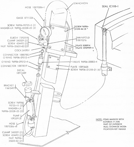
The turret ring of the M48A3 was able to be pneumatically sealed for fording operations or to help prevent ingress of chemical agents. The driver was provided with a hand pump and a pressure gage, and was to inflate the seal to 5-7psi (.35-.49kg/cm²) when needed. To prevent damage to the seal, it needed to be deflated using the bleeder valve below the gage before the turret was traversed. (Picture from Conversion Guide Covering Modification of Tank, Combat, Full Tracked: 90-mm Gun, M48A1 to Tank, Combat, Full Tracked: 90-mm Gun, M48A3 (Mod. B) Volume 1 of 2 Hull.)
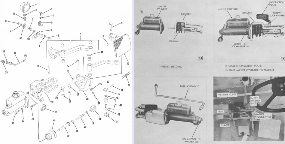
The new brake pedal and master cylinder for the hydraulic brake system of late tanks are exploded on the left, and the installation of the master cylinder is detailed on the right. (Picture from Conversion Guide Covering Modification of Tank, Combat, Full Tracked: 90-mm Gun, M48A1 to Tank, Combat, Full Tracked: 90-mm Gun, M48A3 (Mod. B) Volume 1 of 2 Hull.)
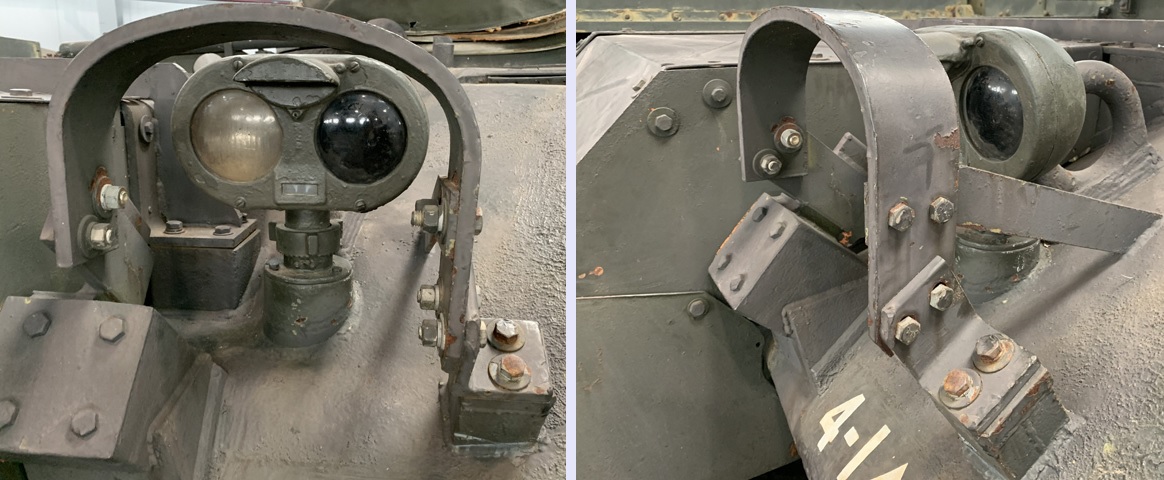
M48A2-style detachable headlights returned on the M48A3 (Mod. B), protected by substantial brush guards.
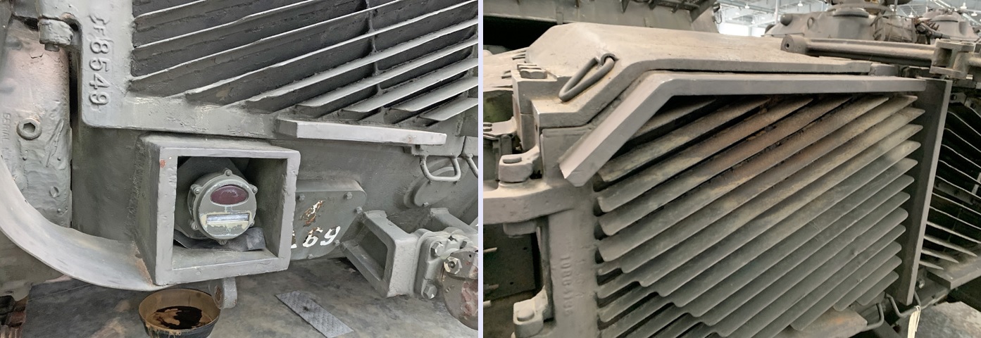
The armor framing around the taillights and along the tops of the rear grille doors can be contrasted with earlier tanks above that lacked these features.
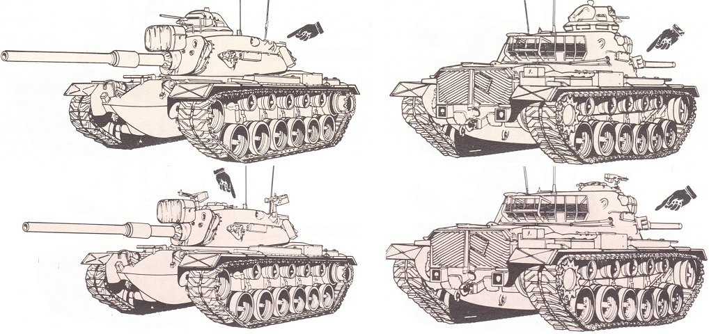
When directly compared, the low-profile cupola makes a striking difference in height when compared to the earlier cupola M1 with the vision block riser. (Picture from TM 9-2350-258-10 C5.)
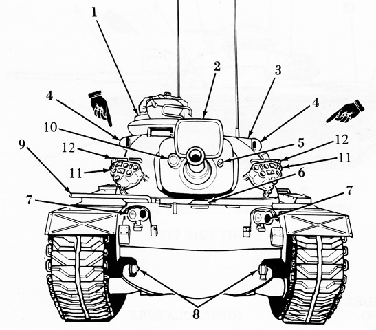
The front of an M1 cupola-equipped tank is shown here. 1. Commander's cupola. 2. Searchlight. 3. Turret. 4. Rangefinder. 5. 7.62-MM machinegun. 6. Driver's hatch. 7. Headlights. 8. Towing hooks. 9. Heater exhaust pipe. 10. Telescope. 11. Smoke grenade discharger. 12. Smoke grenade storage box. (Picture from TM 9-2350-258-10 C5.)
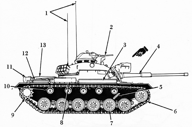
1. Antenna (2). 2. Caliber .50 machinegun. 3. Stowage box. 4. 105-MM gun. 5. Shock absorber. 6. Track. 7. Roadwheel. 8. Air cleaner. 9. Drive sprocket. 10. Support roller. 11. External interphone control box. 12. Stowage box. 13. Engine compartment. (Picture from TM 9-2350-258-10 C5.)
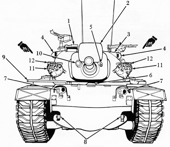
A tank with the low-profile cupola is labeled. 1. Commander's cupola. 2. Searchlight. 3. Turret. 4. Rangefinder. 5. 7.62-MM machinegun. 6. Driver's hatch. 7. Headlights. 8. Towing hooks. 9. Heater exhaust pipe. 10. Telescope. 11. Smoke grenade discharger. 12. Smoke grenade storage box. (Picture from TM 9-2350-258-10 C5.)
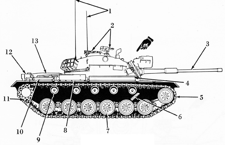
1. Antenna (2). 2. 7.62-MM machinegun (2). 3. 105-MM gun. 4. Stowage box. 5. Track. 6. Shock absorber. 7. Roadwheel. 8. Air cleaner. 9. Support roller. 10. Stowage box. 11. Drive sprocket. 12. External interphone control box. 13. Engine compartment. (Picture from TM 9-2350-258-10 C5.)
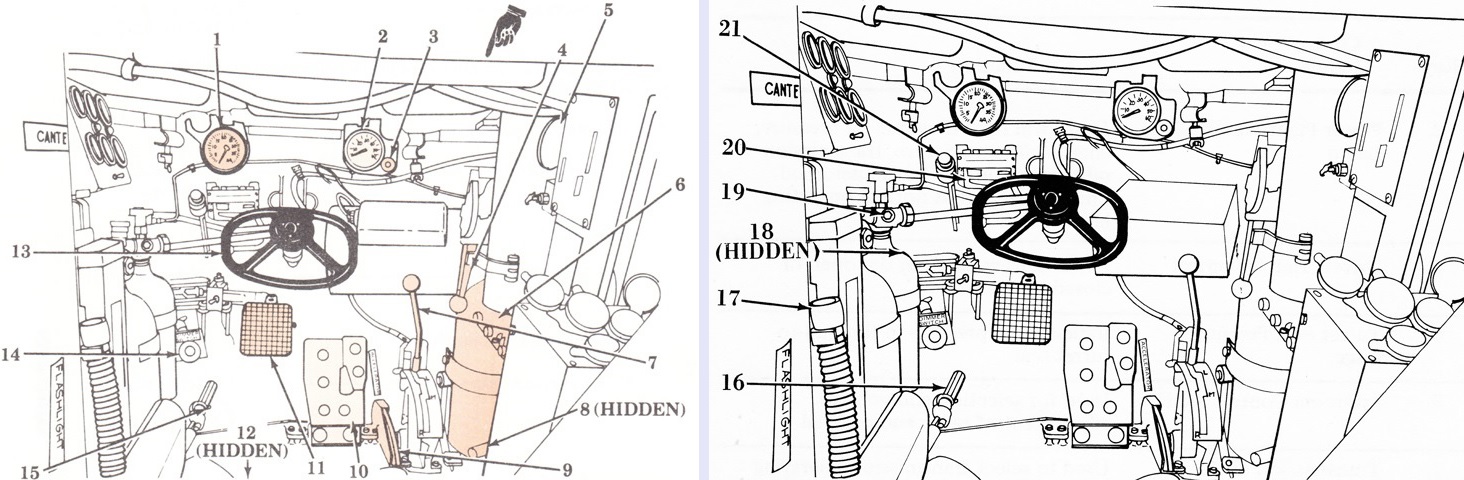
The driver's position is shown in these two images. 1. Tachometer, hour meter. 2. Speedometer, odometer. 3. Power plant warning lamp. 4. Drivers [sic] hatch control. 5. Turret seal pressure gage. 6. Intercom control panel. 7. Transmission shift lever. 8. Turret seal pump. 9. Accelerator lock lever. 10. Accelerator pedal. 11. Brake pedal. 12. Escape hatch lever. 13. Steering control. 14. Dimmer switch. 15. Purge pump. 16. Manifold heater switch. 17. Gas particulate filter hose. 18. Brake pressure gage. 19. Fixed fire extinguisher controls. 20. Domelight. 21. Rheostat knob. (Picture from TM 9-2350-258-10 C5.)
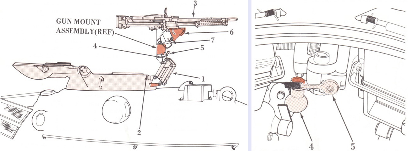
The low-profile commander's cupola and machine gun mount are detailed in these sketches. Illustrated on the left, the machine gun could be used in a low or elevated firing position; moving the handle back would raise the mount. 1. Scissors mount assembly. 2. Commander's cupola. 3. 7.62-mm M60D machinegun. 4. Detent locking pin. 5. Handle. 6. Cradle. 7. Pin.
As shown on the right, the low-profile cupola had a locking lever in the rear and was traversed via the traverse handle (4). The rate of traverse was controlled via the azimuth retarder (5). (Picture from TM 9-2350-258-10 C5.)
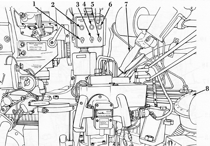
The gunner's controls are labeled in this drawing. 1. Machinegun switch. 2. Machinegun power indicator. 3. Main gun switch. 4. Main gun indicator. 5. Turret power switch. 6. Turret power indicator. 7. Manual traversing handle. 8. M28A1 azimuth indicator. (Picture from TM 9-2350-258-10 C5.)
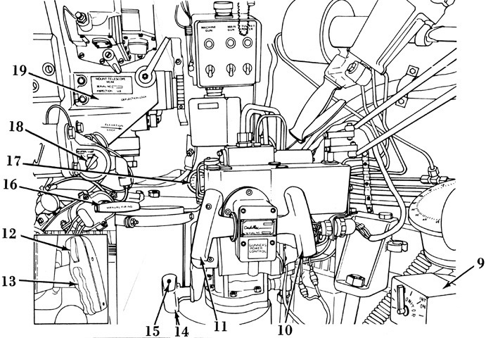
9. Intercom and control box. 10. Gunners [sic] elevating handle. 11. Gunners [sic] traversing handle. 12. Firing trigger. 13. Magnetic brake switch. 14. Manual elevating handle. 15. Firing button. 16. Manual firing handle. 17. Power pack pressure gage. 18. Light source control knob. 19. M114 mount. (Picture from TM 9-2350-258-10 C5.)
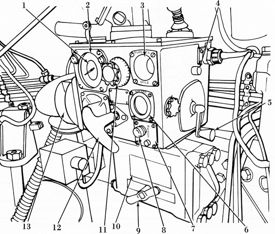
The ballistic computer M13A4 is drawn here. 1. Inner (range) pointer. 2. Outer (superelevation) pointer. 3. Superelevation mil counter. 4. Rheostat knob. 5. Superelevation crank. 6. Ammo indicator. 7. Reset button. 8. Indicator lamp. 9. Locking handle. 10. Turret lock. 11. Range correction knob. 12. Ammo selector handle. 13. Circuit breaker. (Picture from TM 9-2350-258-10 C5.)
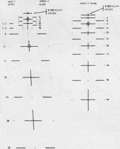
With the change to the 105mm gun, the gunner's telescope received reticles for the new ammunition types. The reticle on the left featured M393 HEP-T from 350m to 3,200m on the left and M392 APDS-T from 400m to 2,800m on the right, while the reticle on the right of the picture was used with M456 HEAT-T from 400m to 4,400m. When using APERS-T ammunition, a data plate was used to convert the range for HEAT-T to the appropriate range for APERS-T. (Picture from TM 9-2350-258-10 C5.)
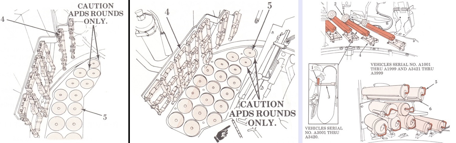
In the left image, the original 105mm ammunition ready rack on the left is compared to the rack for tanks with with increased stowage on the right. 4. Rack. 5. Pad.
Two different turret ammunition racks could be found, and their operation is compared in the right image. 1, 5. Handle. 2, 6. Rack. 3. Hinge. 4. Retainer. (Picture from TM 9-2350-258-10 C5.)
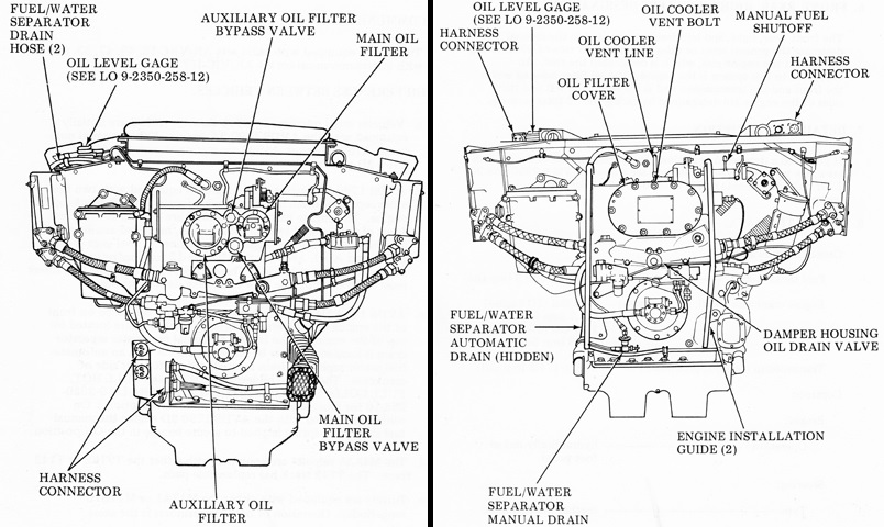
Tanks with serial numbers A3001-A3999 were built with the AVDS-1790-2A engine, seen on the left, while A1001-A1999 were equipped with the AVDS-1790-2D on the right. The AVDS-1790-2A had two fuel/water separator drain hoses and valves on the engine's left front top. Engine harness connectors were found at the lower left front, and the main and auxiliary oil filter covers were also on the front. Its engine oil level gage was graduated as FULL or ADD. After each day's operation, the engine's fuel filters needed to be drained by the crew.
The AVDS-1790-2D had one oil filter on the front, and its engine harness connectors were on the front top. A manual fuel/water separator drain was found at the lower left front of the engine, with an automatic one on the left front of the crankcase. Its oil level gage was graduated with FULL HOT, FULL COLD, IDLING RANGE, and ADD. The manual fuel shut off was spring loaded so that the handle was secured in the ON position. (Picture from TM 9-2350-258-10 C5.)
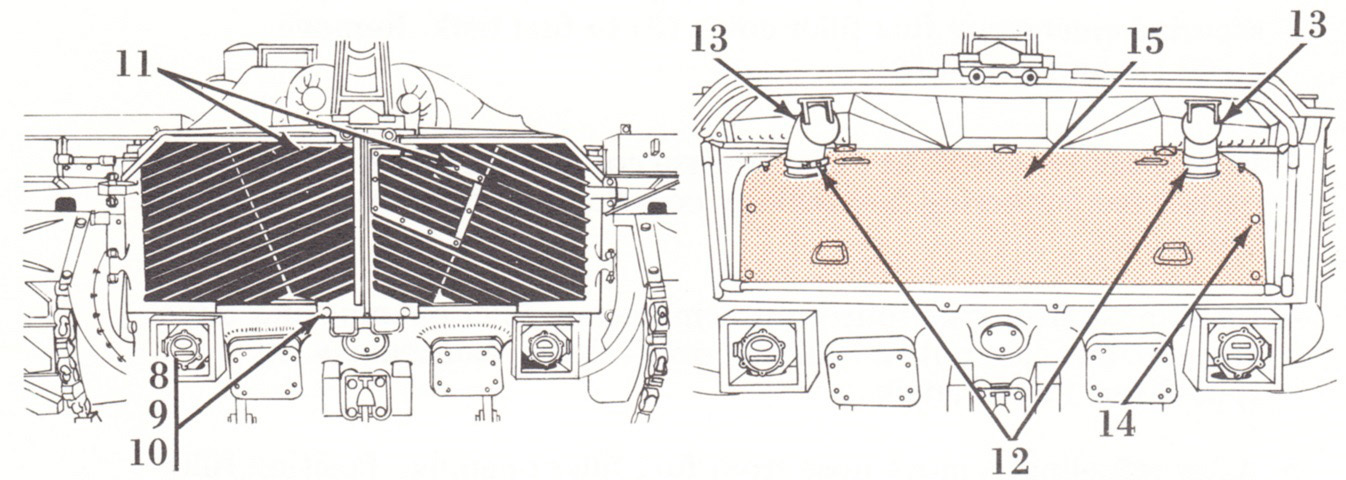
The rear grille doors are shown closed and open. 8. Screw (4). 9. Lockwashers (4). 10. Flat washers (4). 11. Rear grille doors. 12. Exhaust elbow clamps. 13. Exhaust elbow. 14. Cam screws (6). 15. Shroud. (Picture from TM 9-2350-258-10 C5.)
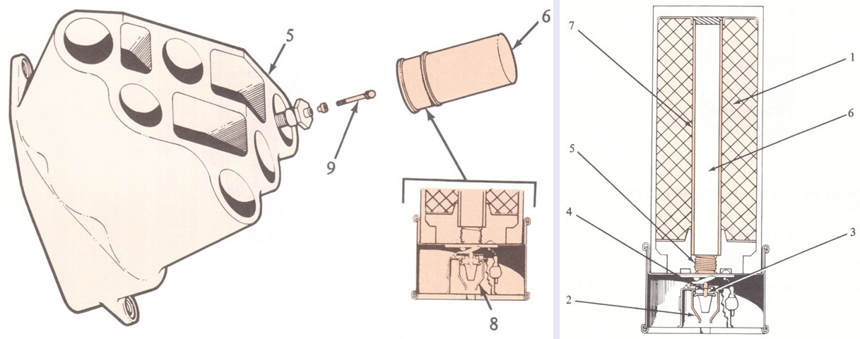
A smoke grenade is being loaded into the M239 launcher on the left, and a cross-section of an L8A1 smoke grenade is shown on the right. Developed by the United Kingdom, the grenades were 66.3mm diameter, 185mm long, and weighed .68kg (1.5lb). The legend for the left image is: 5. Discharger. 6. Grenade. 8. Spring clip. 9. Tip plug.
The legend for the right image is: 1. Red phosphorus/butyl rubber composition. 2. Firing contact. 3. Fuze. 4. Propellant charge. 5. Delay holder. 6. Gunpowder bursting charge. 7. Rubber case. (Picture from TM 9-2350-258-10 C5.)
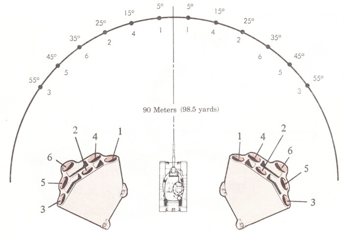
The spread of smoke grenade coverage is illustrated here. Two salvo buttons were available to the commander: the left button launched grenades 3, 6, and 4 from the left discharger and grenades 1, 2, and 5 from the right. The right salvo button launched the other grenades. (Picture from TM 9-2350-258-10 C5.)
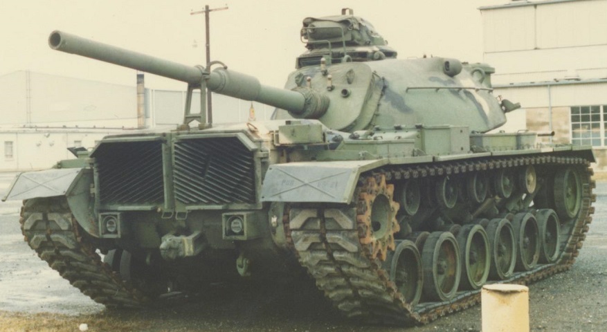
From this angle, the M48A5 can be difficult to discern from the M60, but the commander's cupola shape and number of return rollers can help our identification. The armor framing along the tops of the exhaust louvres and armored boxes around the taillights that first appeared on the M48A3 (Mod. B) are visible in this rear view, and the raised position of the infantry telephone can be contrasted with this image. (Photo by Richard S. Eshleman.)
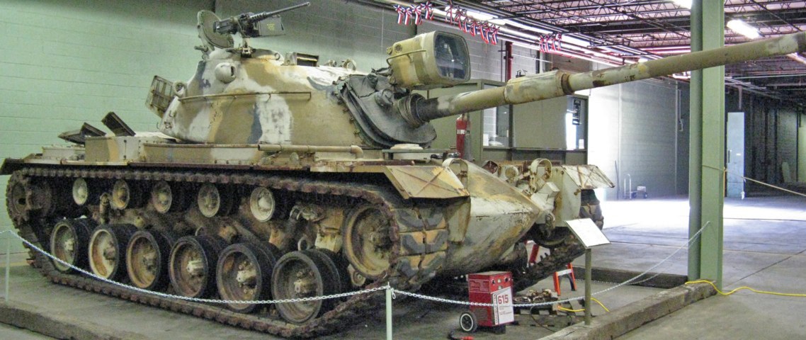
This M48A5 is sporting the Israeli-designed low-silhouette commander's cupola, and the stark contrast between the two designs is apparent when this vehicle is compared with the tank above. The bore evacuator of the 105mm gun M68 is visible, as is the right-hand "eyeball" of the coincidence rangefinder near the center of the turret. The taller box just behind the long fender stowage box is an engine air cleaner housing. The xenon searchlight is not plugged in to its power receptacle on the turret roof. A .50cal machine gun is mounted on the commander's cupola; the low-profile cupola usually sported a 7.62mm M60D machine gun. This tank was fitted with the later headlights first found on the M48A3 (Mod. B), and their brush guards can be contrasted with the tanks above.
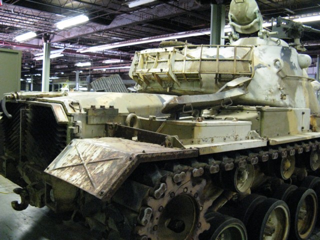
The engine intake grille doors are open on this vehicle, and the commander's cupola hatch arms can be seen as well.
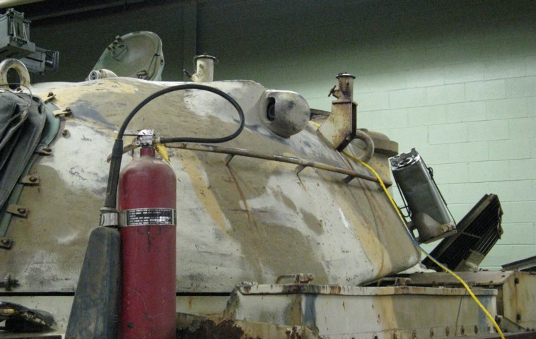
The loader was provided with two mounts for his M60D machine gun, and both are visible in this image. The power receptacle for the tank's searchlight can also be seen in front of the TC's cupola.
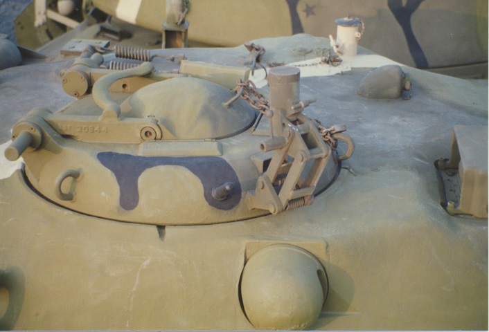
A closer look at the low-silhouette commander's cupola is provided here. The positioning of the three periscopes in the cupola housing can be seen in front and to the sides of the hatch door, and the details of the machine gun mount can be gleaned as well. The springs of the loader's hatch door are in the background. The cupola weighed 340kg (750lb) and its height was 24cm (9.4") above the hull roof. (Photo by Richard S. Eshleman.)
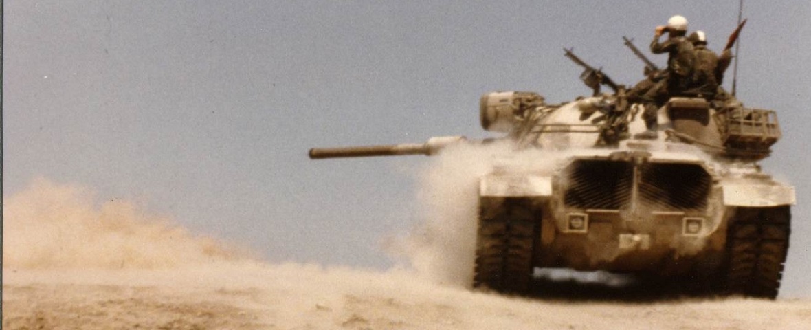
This tank is from C Company, 3/161 Armor, and features the low-silhouette cupola and M60D machine guns. The loader's weapon is situated on the roof mount to the front of his hatch. The crew was being assessed on Tank Table VIII, and an evaluator is sitting on the turret. (Photo by Rob Coach.)
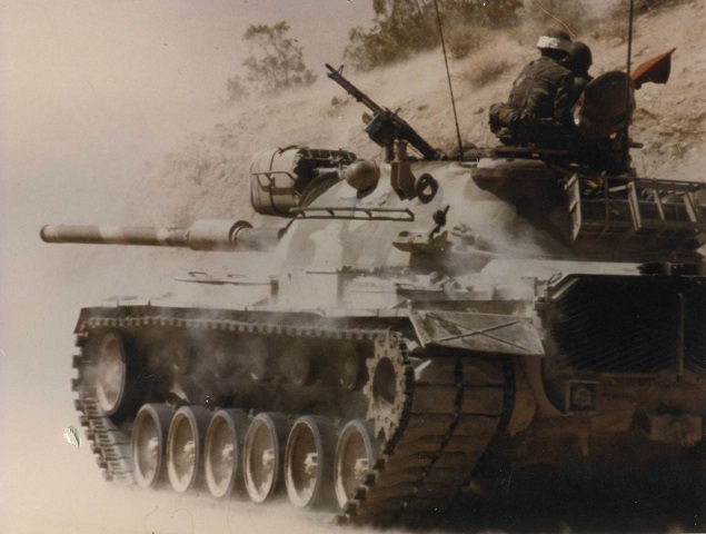
Another view of the loader's machine gun in the forward mount is provided here. The grips are protruding a bit into his hatch opening. (Photo by Rob Coach.)
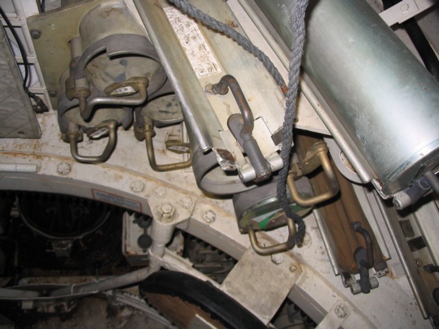
This tank has also been fitted with the M48A5PI features, including the increased ammunition stowage. Nine rounds were stowed in the left side of the turret bustle behind the loader.
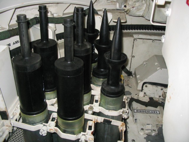
In front of the loader's position, to the left of the main gun, is a nineteen-round ready rack. This tank is fitted out with replica HEAT and sabot ammunition.
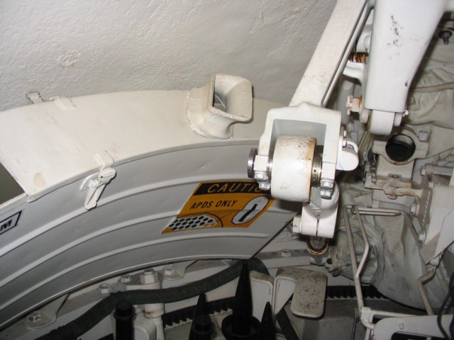
Above the 105mm ready rack is the coaxial machine gun ready ammunition box, which could hold 2,200 rounds. The feed chute can be seen towards the front of the box, and the cradle for the coaxial machine gun is visible to the right of the picture.
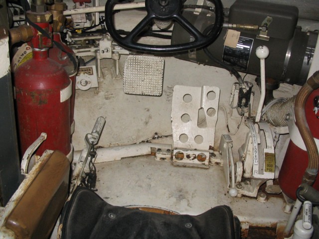
An overview of the driver's position is seen here. He used the black steering wheel to control direction, and the brake and accelerator pedals are below the wheel to the left and right, respectively. The red bottles are fire extinguishers, and the green tube to the front of the driving compartment is the crew heater. The lever to the driver's left in front of the fire extinguisher bottles is the purge pump, and the pump handle to the right of the driver's seat is the turret seal pump. The transmission shifting control lever is marked for park, neutral, and low, high, and reverse ranges. Between the accelerator pedal and the transmission shifting control lever is the throttle lock lever.
When in reverse, turning the steering wheel to the right caused the vehicle's rear to swing to the left, and vice-versa. When in neutral, the tank would pivot to the right or left by turning the wheel in the desired direction.
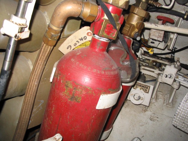
The left side of the driver's compartment is highlighted here. The dimmer switch is labeled, and the red fire extinguisher control handle can be seen towards the vehicle's front. Twelve main gun rounds were stowed in the green tubes behind the fire extinguisher bottles, and a nine-round rack was placed on the right side of the driver's compartment.
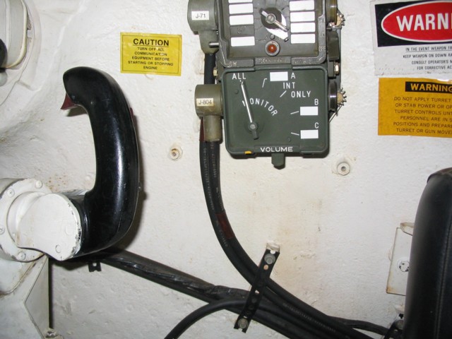
The right side of the tank commander's position is shown here. His control handle allowed him to operate the turret and weapons, and the green boxes are the vehicle's intercom controls.
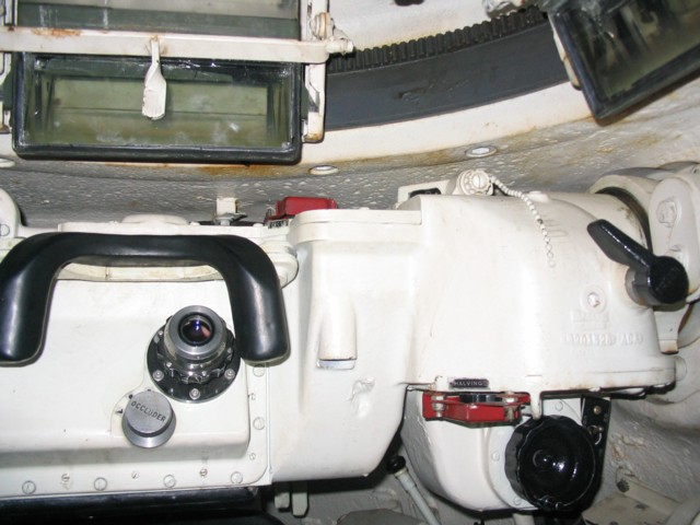
The eyepiece for the M17B1C rangefinder is found in the forward area of the commander's station. Just below the eyepiece is the occluder knob, and the large black knob below and to the right is the ranging knob. The halving knob is located just above the ranging knob, and above and to the right is the filter lever. The red knob above the eyepiece is the ICS knob, and the range scale window can just be seen to the right of the ICS knob. Two of the three periscopes in the TC's cupola are visible in this shot.
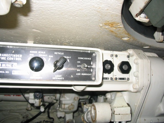
Above the main gun is positioned the instrument light panel for the rangefinder. The farthest-left knob dimmed or brightened the range scale, the knob to its right was for dimming or brightening the reticle, and the switch toggled the coincidence and auxiliary gunsights. The next knob to the right is the vertical adjustment knob, and the final knob in the picture is the horizontal adjustment knob. The shaft going forward from the bottom of the rangefinder is the ballistics drive link assembly, part of the ballistic drive that attached the gun mount elevation system, gunner's sight, commander's telescope, and ballistic computer.
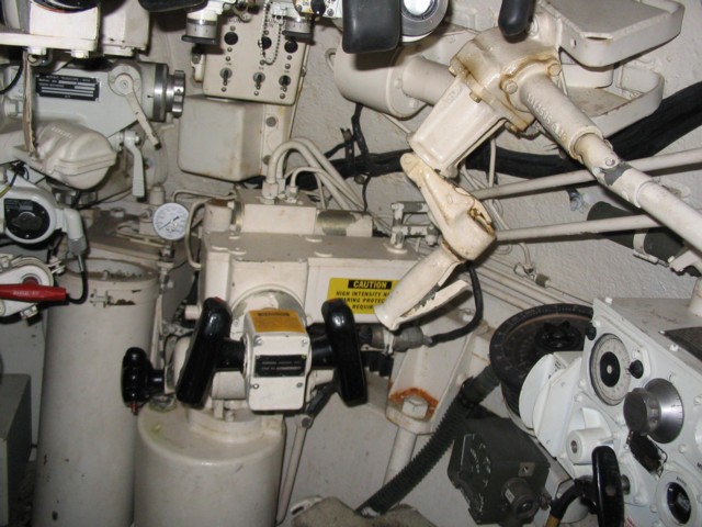
The gunner's controls are shown here. Powered traverse and elevation were accomplished by the control handles in the center of the picture. The black manual elevating handle is located behind the control handles, and the red button on this handle is the gun firing button. The white handle above the control handles was for hand traversing the turret. The red handle on the left side of the picture was for manually firing the main gun. From left to right, the selector switchbox to the front of the tank activated the coaxial machine gun, the main gun, and turret power. Just below the selector switchbox is the gunner's relay box, and the superelevation actuator is just to the switchbox's right. The gauge behind the gunner's control assembly showed the accumulator pressure. To the right of the picture is the ballistic computer, and the gunner's dial-like azimuth indicator is just beyond this. A green intercom control box is below the azimuth indicator. The container below the gunner's control assembly is an oil reservoir.
