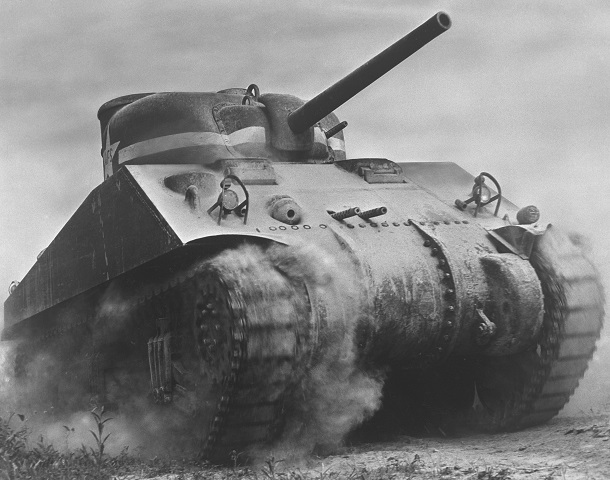
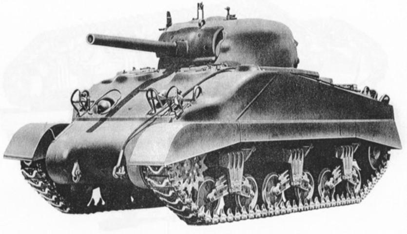
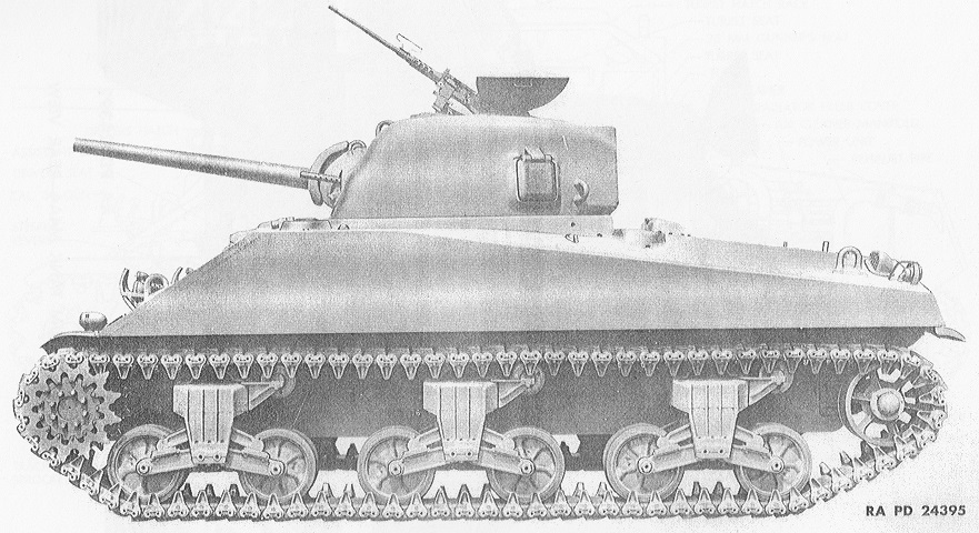
Medium Tank M4A1 Sherman.
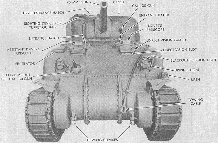
Details of the front of the early M4A1 are shown in this image. It features the combination gun mount M34, three-piece final drive and differential cover, direct vision slots for the drivers, and the rotor sight for the gunner. The latter was replaced by a simple periscope very early in the production run due to its propensity to become damaged and allow entry of bullet splash. (Picture from TM 9-731A Medium Tanks M4 and M4A1.)
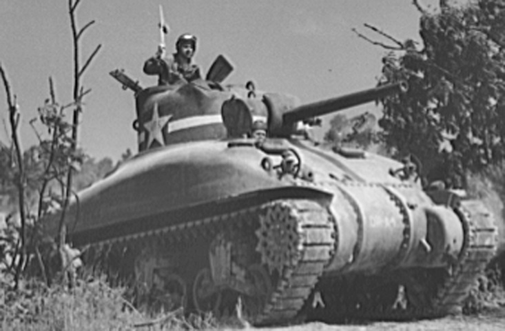
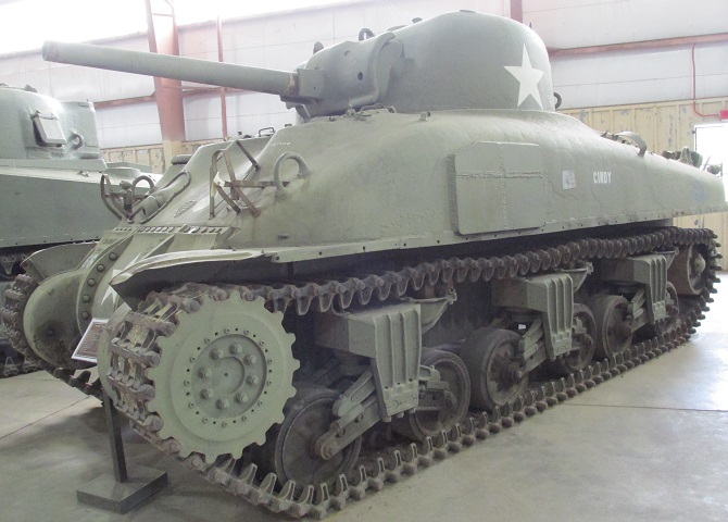
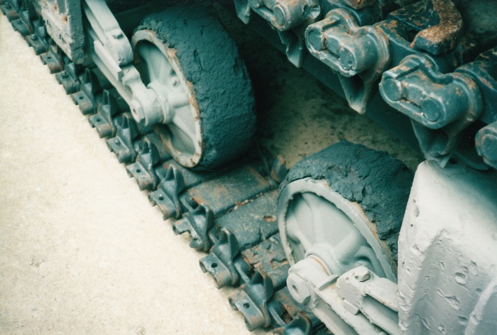
This tank retains the early-type suspension bogie with the return roller directly atop; also present are the two apertures in the hull front for the fixed machine guns, although these are not fitted. (Picture taken in July 1942 by Alfred T. Palmer; available from the Library of Congress.)
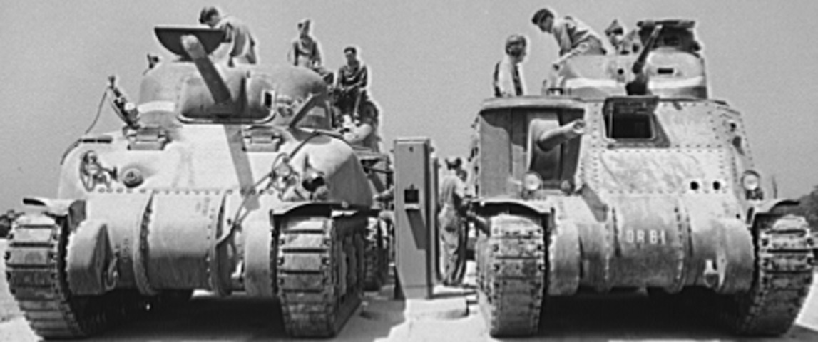
Here a medium tank M4A1 can be compared with a medium tank M3 as they both pause to refuel. (Picture taken in July 1942 by Alfred T. Palmer; available from the Library of Congress.)
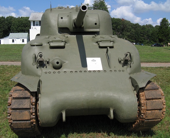
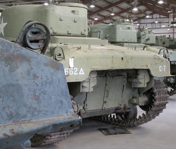
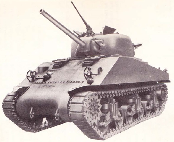
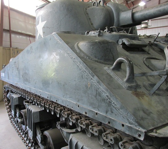
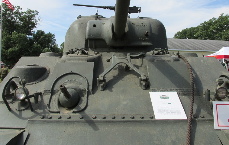
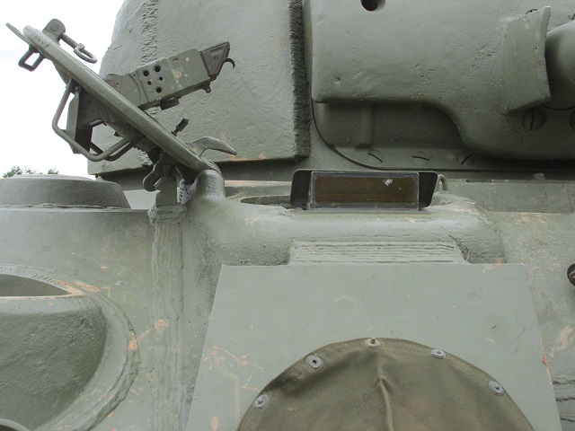
This tank presents an interesting mix of early and late production features. It has the single-piece final drive and differential housing and the combination gun mount M34A1 but retains the drivers' direct vision slots. The guard on the hull front in front of the driver was to protect the siren when it was mounted, and the vertical vane sight is visible on the turret roof in front of the commander's position. This would help roughly line the turret up with a target. The two small cylinders attached to the headlight brush guards held plugs used to seal the headlight socket hole when the light assemblies were removed. When used as a command tank and with a second radio installed, the ventilator next to the assistant driver was used for the radio's antenna. This contrasts with welded hull tanks below, which have a separate antenna base.
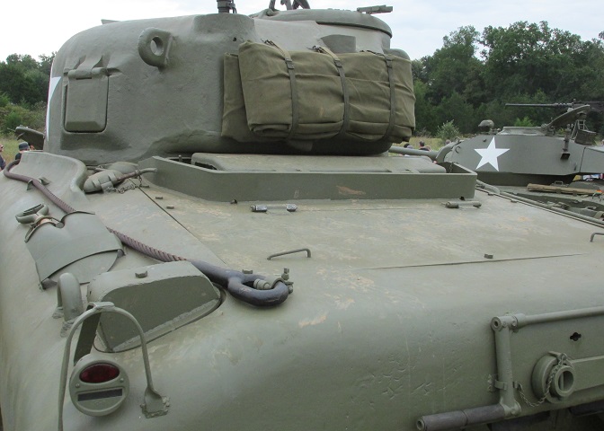
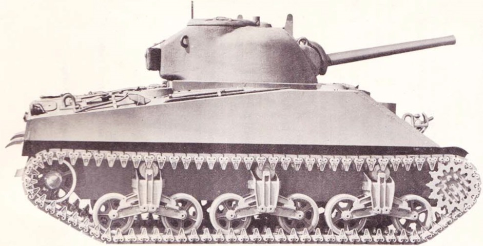
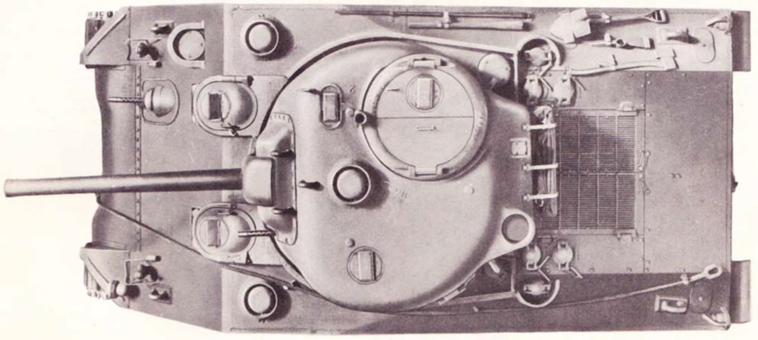
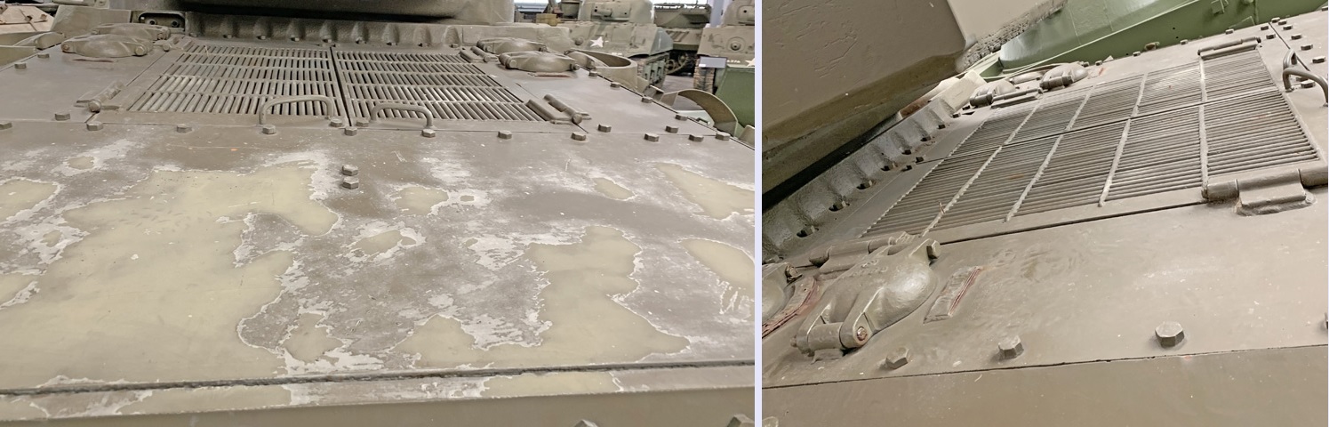
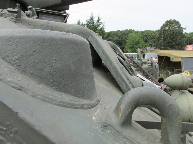
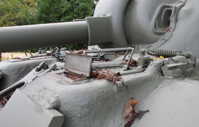
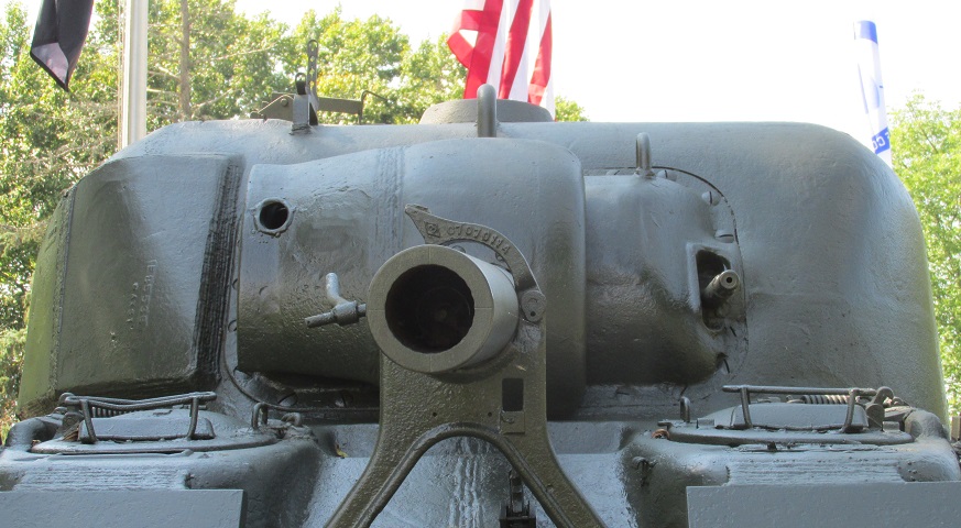
A view of the rear deck and turret is shown here. The engine air inlet cover and its protective armor splash guard are near the turret, and the hinges for the solid rear deck engine access door are just to the rear of the air inlet cover. A pistol port was provided in the turret at the loader's station, and a lifting eye is above and behind the pistol port. This angle also allows us to see the splash guard that protected the turret ring as well as the main engine and auxiliary generator engine fuel fillers, which can be seen near the turret in the foreground and background, respectively. Stowage on the rear armor plate included the large idler adjusting wrench and the hand crank for the engine. Note the orientation of the shovel on the left side of the hull.
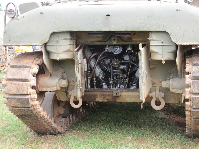
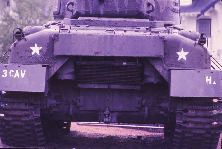
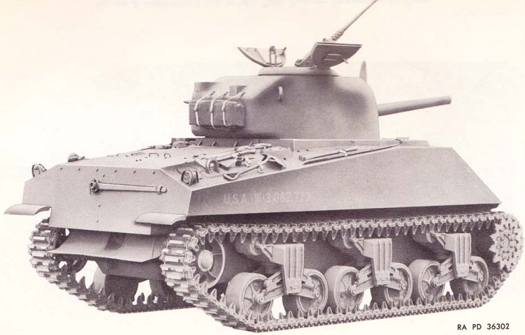
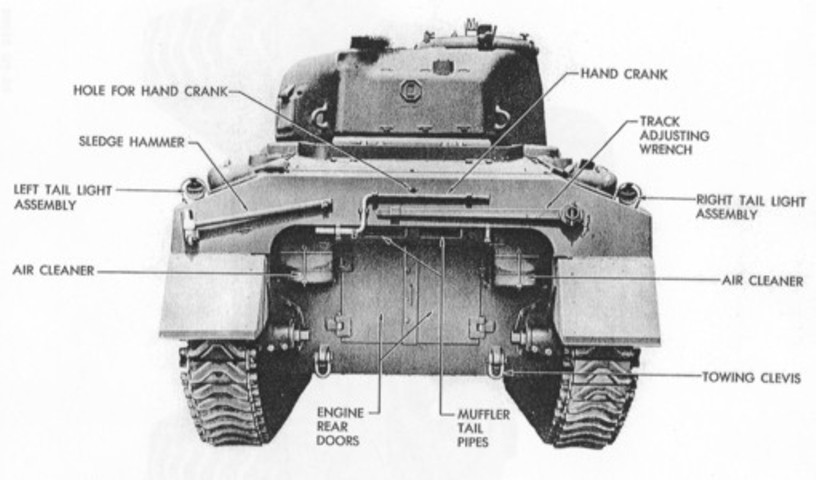
This rear view of an M4A1 illustrates differentiation points it shares with the M4. The rear hull plate has a shallow horseshoe shape, and the engine's air cleaners are visible at the top corners. The twin engine access doors are open in this picture, and the hole in the rear armor above the engine was for insertion of the engine's hand crank. The square muffler tailpipes are visible protruding from under the armor plate. The very bottom of the hull between the tracks is angled down as opposed to being rounded, indicating this tank was manufactured by Pressed Steel Car Company. The air inlet hoses can be seen angling down diagonally from the air cleaners toward the vehicle's center, and the black boxlike carburetor sits between them. The squat, cylindrical fuel pump is visible near the center of the rear hull opening, and has two hoses attached to it. The shorter vertical hose connects the fuel pump to the carburetor.
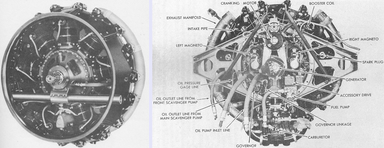
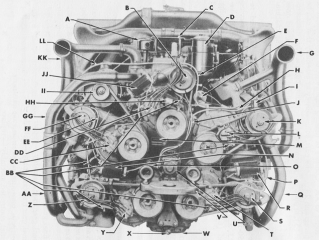
The rear of an early R975 C1 engine is shown on the right. Later engines can be readily recognized by the generator being driven by the propeller shaft or transmission, and consequently not being mounted on the engine's accessory case. The engine had a 5.7:1 compression ratio; and its cylinders had a bore of 5.00" (12.7cm) and stroke of 5.50" (14.0cm), for a displacement of 973in³ (15.9L). The engine is seen from the left front in the left image. The front was considered the flywheel end, and right and left were determined by looking at the engine from the rear. Including accessories, the engine weighed 2,240lb (1,020kg). (Picture from TM 9-1751 Ordnance Maintenance--9-Cylinder, Radial, Gasoline Engine (Continental Model R975-C1) and TM 9-731A Medium Tanks M4 and M4A1.)
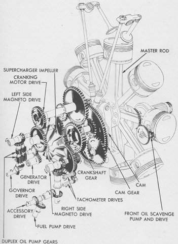
A diagram of the gear train is drawn here. The supercharger impeller diameter was 6 ⅞" (17.46cm), and its ratio was 10.15:1. (Picture from TM 9-1751 Ordnance Maintenance--9-Cylinder, Radial, Gasoline Engine (Continental Model R975-C1).)
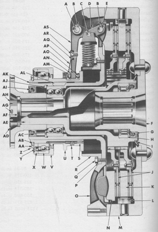
This sketch is a cross-section of the clutch. A. Release lever to flywheel ring pin. B. Cotter pin. C. Link pin. D. Link. E. Pressure plate to link pin. F. Flywheel hub. G. Spindle oil retainer (large). H. Spindle roller bearing. I. Oil slinger. J. Driven disk assembly. K. Driving plate. L. Driving plate driving pin. M. Flywheel. N. Pressure plate. O. Flywheel ring. P. Pressure spring carrier lock washer. Q. Pressure spring carrier cap screw. R. Pressure spring carrier. S. Pin. T. Pipe plug. U. Sleeve. V. Bearing housing. W. Bearing. X. Inner seal. Y. Outer seal. Z. Retainer. AA. Lock ring. AB. Snap ring. AC. Spindle ball bearing. AD. Spindle flange. AE. Spindle. AF. Spindle nut washer. AG. Cotter pin. AH. Spindle nut. AI. Spindle oil retainer (small). AJ. Lock ring. AK. Oil wick. AL. Sleeve key. AM. Adjusting screw lock nut. AN. Adjusting screw lock washer. AO. Adjusting screw. AP. Release lever spring. AQ. Release lever spring screw lock washer. AR. Release lever spring screw. AS. Release lever. (Picture from TM 9-1751 Ordnance Maintenance--9-Cylinder, Radial, Gasoline Engine (Continental Model R975-C1).)
A closer view of the assistant driver's direct vision slot is provided here. The covers were opened and closed by means of an interior handle.
This tank is fitted with square-sided air cleaners. Round ones were also manufactured.
The twin exhaust pipes reach under the hull rear into the engine compartment.
The transmission and final drive assembly has been removed from the tank. This early version had a parking brake in a housing bolted to the rear of the transmission; later, a pawl attachment to the steering levers was used. Using arms were authorized to remove and install a transmission and final drive assembly, but replacement with another assembly required authorization from ordnance personnel. The assembly weighed 8,800lb (4,000kg), and required a sling, a wrecker, and several hours of work to remove. (Picture from TM 9-731A Medium Tanks M4 and M4A1.)
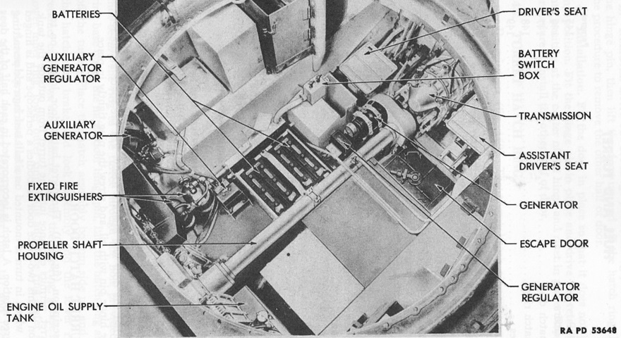
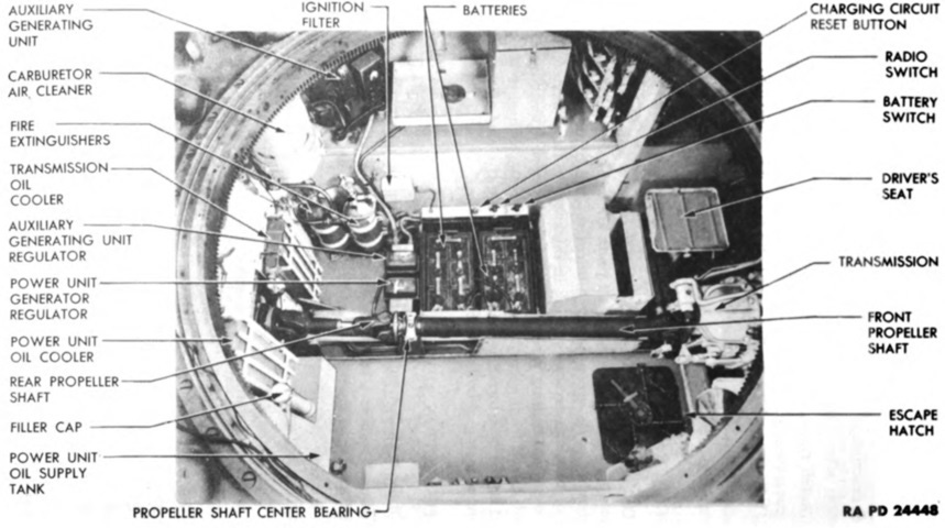
The interior of the fighting compartment is labeled with the turret removed; note the generator adjacent to the propeller shaft on this later-production example. The padding and backrests are absent from both drivers' seats. (Picture from TM 9-731A Medium Tanks M4 and M4A1.)
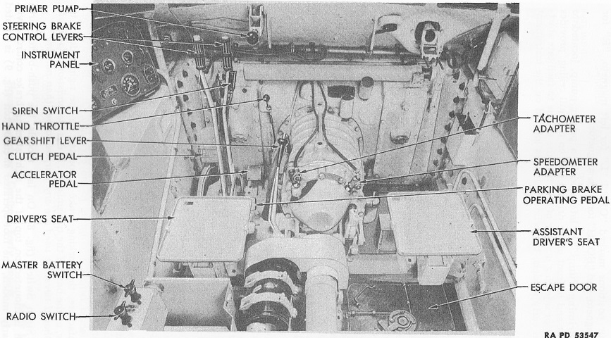
A late-production driver's position is illustrated here. Differences from earlier-production machines included the parking brake pedal at the base of the steering levers, siren switch being hand operated instead of foot operated, instrument panel design, compass location (mounted to the hull roof over the transmission in late-production tanks), primer pump moved from the instrument panel to in front of the driver, and a foot guard being installed on the clutch pedal. (Picture from TM 9-731A Medium Tanks M4 and M4A1.)
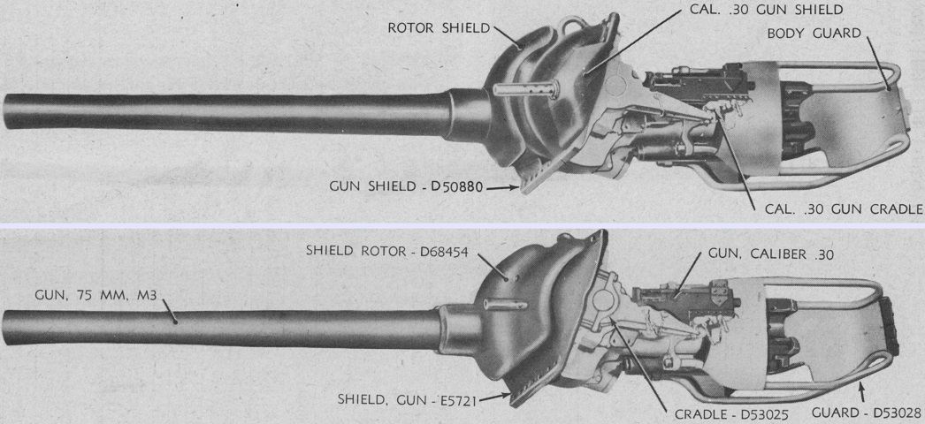
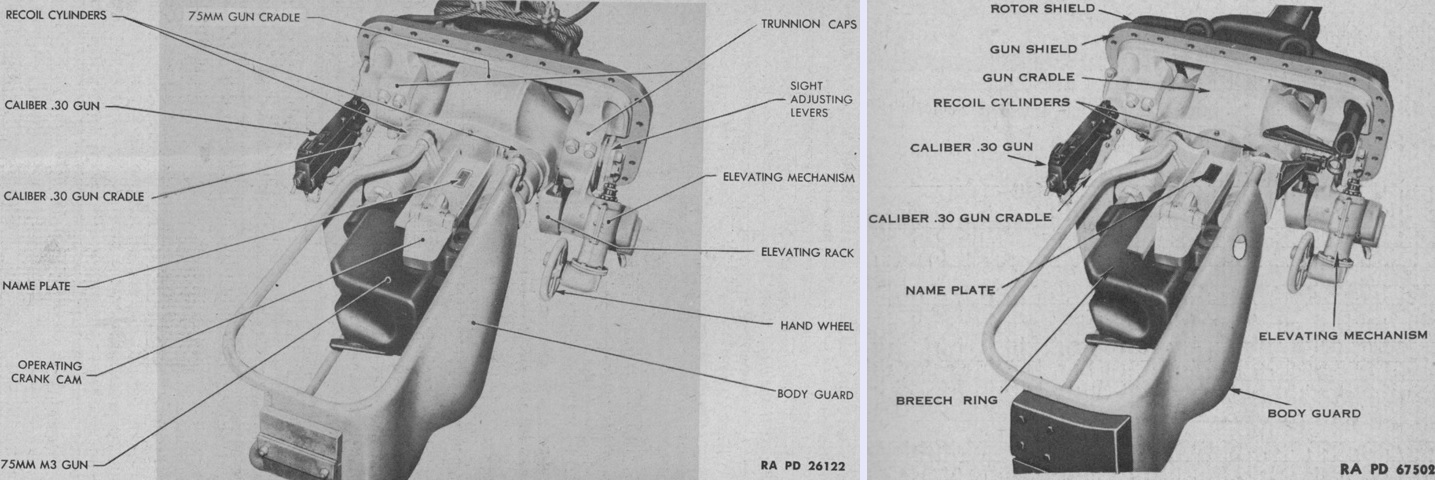
Although not necessarily an M4A1, the combination mounts M34 and M34A1 are illustrated on the left and right, respectively. This M34 features the separate machine gun shield. The M34A1 has a larger rotor shield that protected openings in the gun shield for the the direct sight telescope as well as the coaxial machine gun. The location of the telescope in the M34A1 can be divined by the aperture in the opposite side of the rotor shield. (Picture from TM 9-1307 Ordnance Maintenance--75-mm Tank Guns M2 and M3 and Mounts M1, M34, and M34A1.)
The combination mounts appear quite similar from the left side, apart from the shields and larger counterweight needed to balance the M34A1's rotor shield. (Picture from TM 9-1307 Ordnance Maintenance--75-mm Tank Guns M2 and M3 and Mounts M1, M34, and M34A1.)
From this angle, the telescope mount in the combination mount M34A1 is visible in the right-hand image. The heftier counterweights are better seen from the rear as well. (Picture from TM 9-1307 Ordnance Maintenance--75-mm Tank Guns M2 and M3 and Mounts M1, M34, and M34A1.)
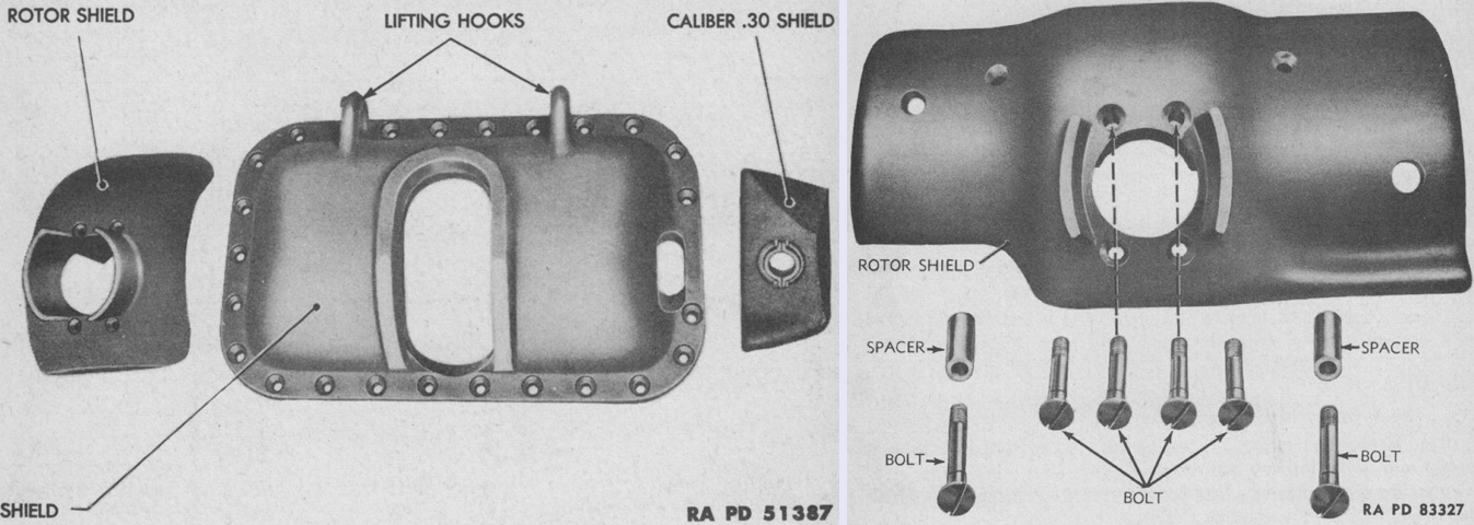
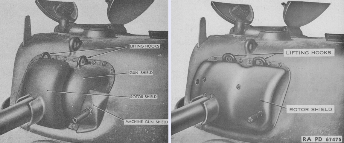
The shields for the combination mounts M34 and M34A1 are shown on the left and right, respectively. The attaching bolts for the M34A1's shield are also present. (Picture from TM 9-1307 Ordnance Maintenance--75-mm Tank Guns M2 and M3 and Mounts M1, M34, and M34A1.)

The 75mm gun could not be removed from the combination mount M34 or M34A1 until the mounts had been taken off of the tank, which involved some disassembly of the turret interior. The mount was secured by 1-1/16" (2.6988cm) bolts and nuts and weighed ~3,000lb (~1,400kg). (Picture from TM 9-1307 Ordnance Maintenance--75-mm Tank Guns M2 and M3 and Mounts M1, M34, and M34A1.)
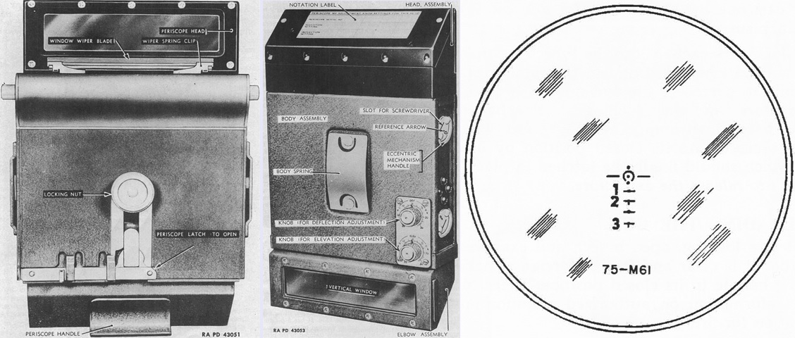
The periscope M4 is seen from the front and rear in the left and center images, and the reticle of the telescope M38 is sketched on the right. A cross line was etched onto the horizontal window of the periscope for use in sighting in an emergency. The telescope M38 attached to the inside right wall of the periscope and provided 1.44x magnification with a 9° field of view. The M38's tube was 5-17/64" (13.37469cm) long, with a 1¼" (3.18cm) diameter objective end and a 0.75" (1.9cm) diameter eyepiece end. The reticle was graduated for the 75mm gun M3 firing the M61 armor-piercing capped projectile. The topmost dot represented 0 range and deflection, and the dots below represented 600, 1,000, 2,000, 2,500, and 3,000 yards (550, 910, 1,800, 2,300, and 2,700m). The arc around the 600 yard (550m) dot had a diameter of 10 mils, and the horizontal lines to each side of and below that dot were also 10 mils long. (Picture from TM 9-731A Medium Tanks M4 and M4A1.)
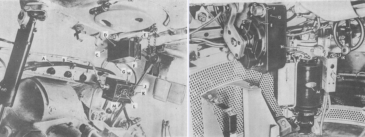
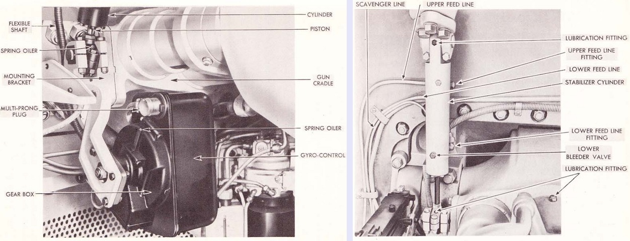
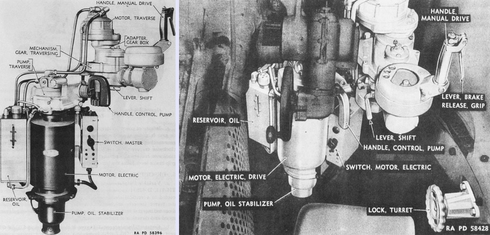
Components of the stabilizer system are shown here. When the stabilizer was operating, the elevation gearing was disengaged and elevation was controlled by the stabilizer's cylinder, which is unlabeled but visible on the left of the image. The elevating handwheel was still used to aim the gun, as movement of the handwheel changed the angular relationship between the gearbox and the gyro control. The gyro control then initiated pressure changes in the cylinder so that the gun would move to the proper angle to keep the gyro control vertical. The legend for the left image is: A. Flexible shaft. B. Clamp. C. Mounting screw. D. Oil reservoir. E. Filler plug. F. Sight glass. G. Drain plug. H. Top cover screw. J. Control box. K. Stiffness rheostat. L. Pilot light. M. Recoil rheostat. The legend for the right image is: A. End cover. B. Gear box. C. Spring oiler. D. Multi-prong plug. E. Gear box clamp. F. Dust shield. G. Gyro control. H. Oil gear traverse. J. Stabilizer switch. K. Firing switch. L. Turret switch. M. Westinghouse motor. N. Oil pump. (Picture from TM 9-731A Medium Tanks M4 and M4A1.)
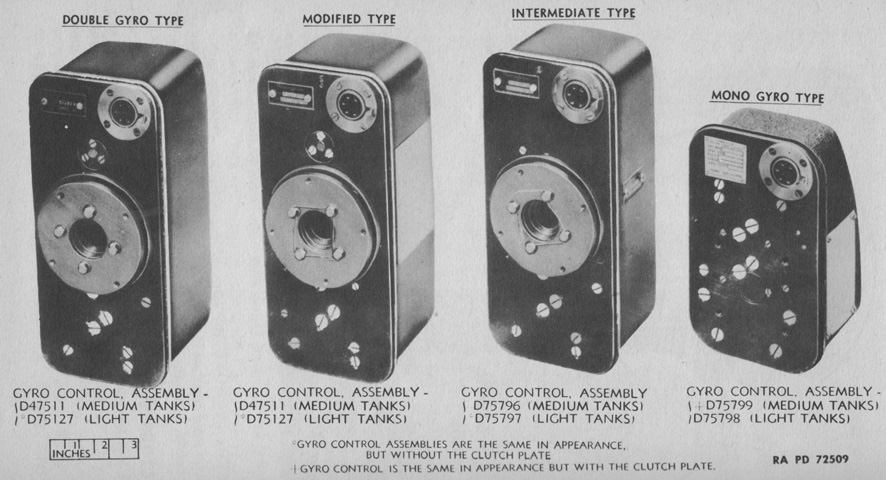
Gyro controls were built with either one or two gyroscopes. The double-gyro control tended to stay vertical, and when moved it created forces to instantly return to vertical. On the other hand, mono-gyro control units did not have a precise reference point, and therefore sometimes would not return to their exact starting point. Mono-gyro controls could slope up to 60° from vertical when influenced by the balance and friction of the gun mount, temperature, and oil pump characteristics. Nonetheless, the mono-gyro control stabilizers gave improved results over the double-gyro control stabilizers, as they were less affected by the movement of their own tank. Consequently, mono-gyros replaced double-gyro stabilizers in production, and double-gyro stabilizers already fielded were modified into mono-gyro stabilizers via Field Service Modified Work Order C-56W1. Intermediate mono-gyro stabilizers were factory produced using the larger double-gyro control bases until these parts were exhausted. As the caption states, any type could be found in light or medium tanks, but those mounted in medium tanks had a clutch on the gyro control base, while the gyro control bases on light tanks lacked this. The clutches are the large bright rings in the center of the left three bases. The example of the final mono-gyro control in the picture above, therefore, is assembly D75798 for light tanks, while the rest are the respective medium tank models. (Picture from TM 9-1334 Ordnance Maintenance--Stabilizers.)
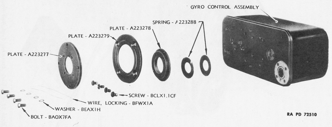
Parts of the clutch use on medium tank gyro controls are labeled here. (Picture from TM 9-1334 Ordnance Maintenance--Stabilizers.)
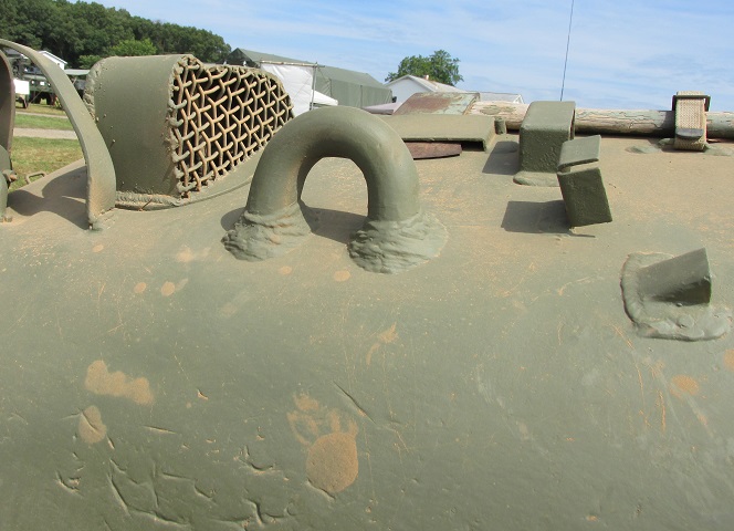
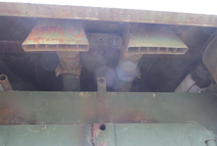
The rear corners of the hull featured an air scoop protected by a mesh screen.
Early production tanks manufactured by the Pressed Steel Car Company featured riveted lower hulls. These rivets can be seen between the suspension bogies.
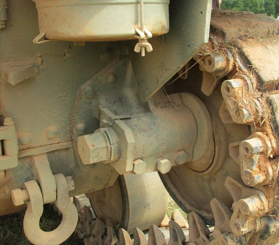
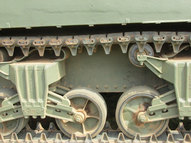
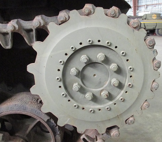
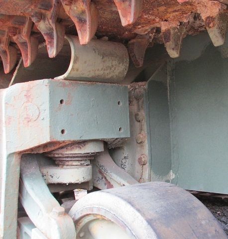
The eccentric adjustment mechanism for the idler wheel is shown here. The large wrench stowed on the outside of the tank was used to turn the large nut on the inboard side of the assembly, extending or retracting the idler wheel to ensure proper track tension. The outer two large bolts on the bottom of the split idler shaft housing are clamping bolts, while the center one is the spreader bolt. Loosening the clamping bolts and driving the spreader bolt into the housing opens the housing, allowing the idler mechanism to be loosened or tightened.
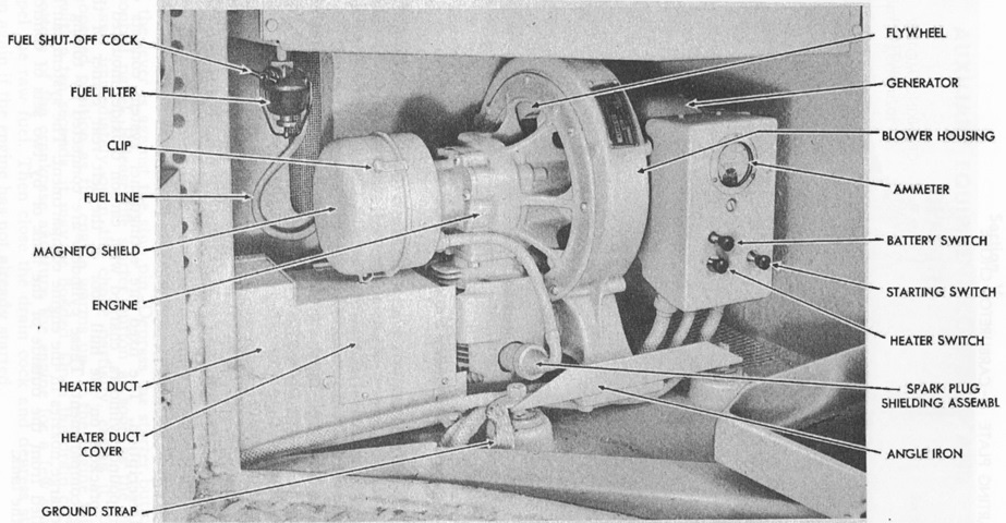
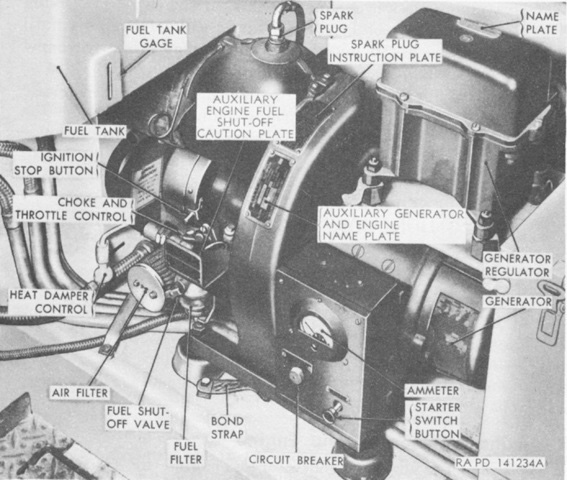
The HRH-28 auxiliary generator carried over from the medium tank M3 was mounted in the rear of the left sponson in the fighting compartment and was fueled from its own 5 gallon (19L) tank. The type fitted to early production tanks is shown here. (Picture from TM 9-731A Medium Tanks M4 and M4A1.)
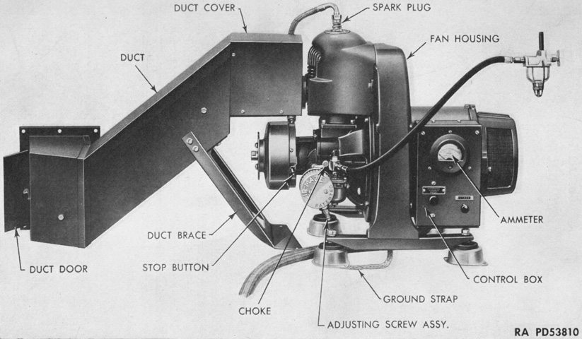
During production, the Homelite HRUH-28 auxiliary generator replaced the HRH-28. It was an integral gasoline engine-driven powerplant designed to provide 1,500 watts, 30 volts of DC. The shunt wound electric generator with attached control box was directly coupled to and driven by a 1-cylinder, air-cooled, 2-cycle gasoline engine with a 2⅜" (6.033cm) bore and 2⅛" (5.398cm) stroke. The engine's speed was 3,400-3,700rpm, and it would consume 1 gallon (3.8L) of fuel every 2 hours under full load. The engine could be started either electrically or by a starter rope. (Picture from Homelite Generator HRUH-28 for Medium Tanks M4 and Modifications.)
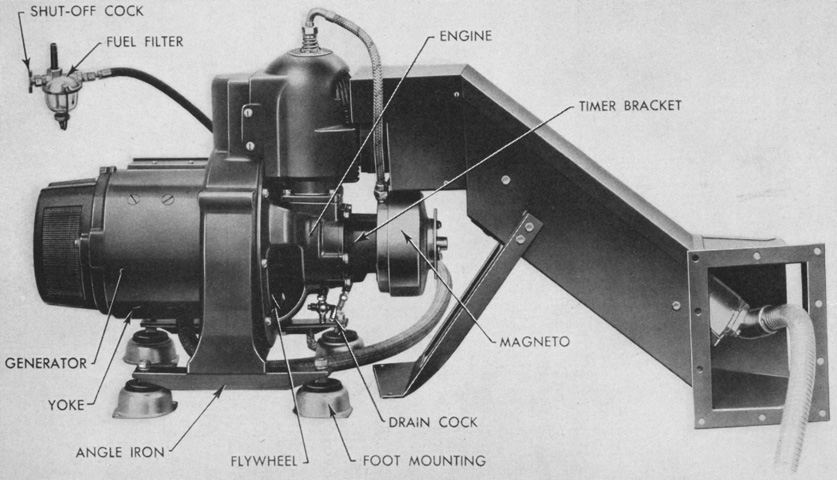
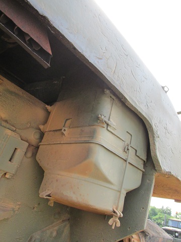
The assembly was mounted on four shock-absorbing feet, and a metal duct containing the muffler was included with units installed in M4, M4A1, and M4A2 tanks in order to carry off engine heat from the crew compartment or to aid in preheating the main engine compartment. Excluding the duct, the assembly was 20" (51cm) high, 15" (38cm) wide, and 21" (53cm) long. Counting the duct, it weighed 140lb (63kg). (Picture from Homelite Generator HRUH-28 for Medium Tanks M4 and Modifications.)
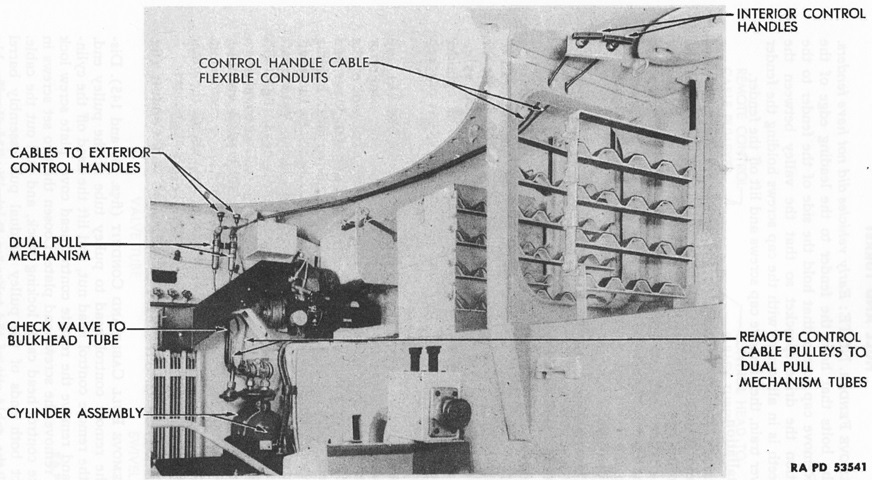
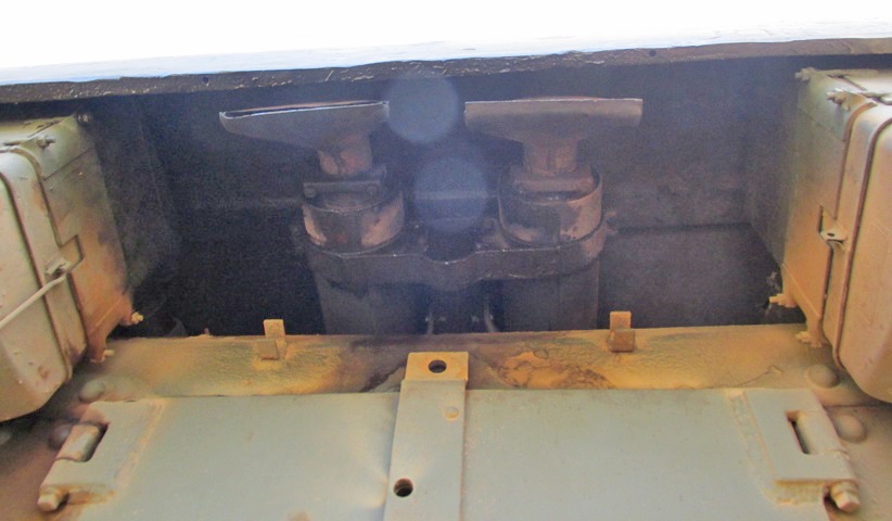
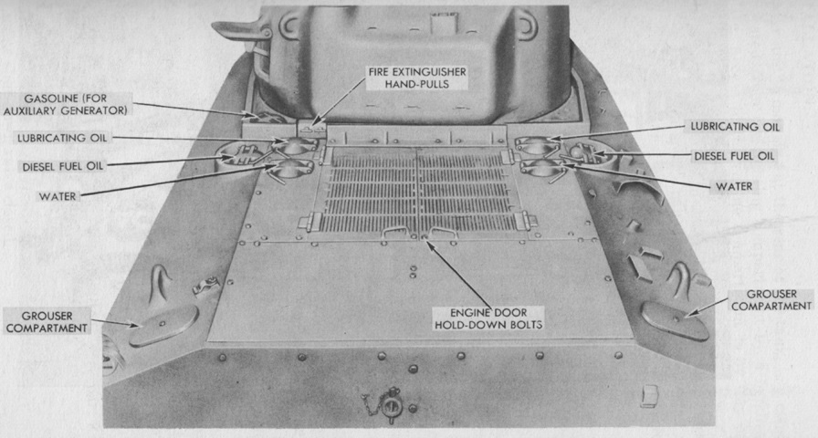
Although the tank pictured is an M4, the fire extinguishing system was common to all Sherman tanks. Two 10lb (4.5kg) CO2 fixed fire extinguishers were mounted at the left rear of the fighting compartment with outlet tubing routed to six discharge nozzles in the engine compartment. Cable-actuated remote control handles were available behind the driver's seat and on the left side of the hull immediately behind the turret. The fixed extinguishers could also be activated by rotating the levers on the cylinders' control heads after removing locking pins. Additionally, portable 4lb (1.8kg) extinguishers were mounted in front of the assistant driver's seat and on the turret platform wall. (Picture from TM 9-731A Medium Tanks M4 and M4A1.)
This tank is fitted with spaced-out suspension that allowed extended track end connectors to be installed on both the outer and inner sides of the track. Spacers were welded to the hull that moved the tank's suspension outwards by 4.5" (11cm), which allowed the 3.5625" (9.0479cm) end connectors to clear the tank hull. With both sets of extended end connectors installed, the track width was increased to 23.6875" (60.1663cm), and ground pressure decreased to ~10psi (~.70kg/cm²). In August 1944, pilots of tanks with these suspension spacers were designated with an -E9 suffix (e.g., M4A1E9), and production of 1000 kits each for field modification and for application to tanks returned for rebuilding was authorized in early 1945. The kits and end connectors added 1,360lb (617kg) to the tanks, and installation required 326 man-hours and at least two skilled welders. This rear view shows to good effect the extra track width provided by the extended end connectors. Note the wider fenders that came equipped with stanchions that attached to the side of the hull. Between the engine air cleaners is a late-production exhaust deflector, more details of which are provided here. A folding blanket rack is mounted on the hull rear plate above the exhaust deflector. (Photo by Richard S. Eshleman.)

The rear engine compartment top plate is missing on this tank, providing us with a top-down view of a mounted engine. The large exhaust pipes in the center of the image emerge from the exhaust collector rings on each side of the engine, and the pot-like crankcase breather can be seen perched atop the engine between the exhaust pipes. The right-hand exhaust collector ring serviced four cylinders, while the left-hand unit took care of the other five. The pipes outside the exhaust pipes chute air from the intake behind the turret to the air cleaners mounted on the hull rear. The right-hand primary booster coil can be seen below the right-side exhaust pipe, and has shielded wires attaching it to the right-hand magneto. Shielded wires on the opposite side of the engine reveal the presence of the left-hand booster coil, though it is hidden by this same exhaust pipe. The exhaust pipe for the auxiliary generator can just be seen between the left-hand main engine exhaust pipe and air inlet pipe near the top of the image. (Picture courtesy Pete Sheppard, via TankNet.)
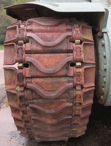
This tank is fitted with the single, dry pin Canadian Dry Pin (CDP) track that was mounted on some cruiser tanks Grizzly I built at the Montreal Locomotive Works. Note that, in contrast to the rubber bushed live track that was mounted on US tanks, the CDP track is very slack across the return run.
The CDP track had a pitch of 4.6" (12cm), necessitating a different drive sprocket with 17 teeth. Due to this size difference, 102-103 shoes per track were installed. The CDP track was 15.5" (39.4cm) wide and made from cast steel. The shorter track pitch and narrower track shoes would both lead to a marginally higher ground pressure for the tank.
Grizzlies were fitted with British-style stowage boxes on the turret rear. The box itself is absent from this vehicle, but the mounting brackets remain on the turret bustle. Also note the channel at the end of the rear deck just above the hole for the engine's hand crank; this was characteristic of early hulls cast by General Steel.
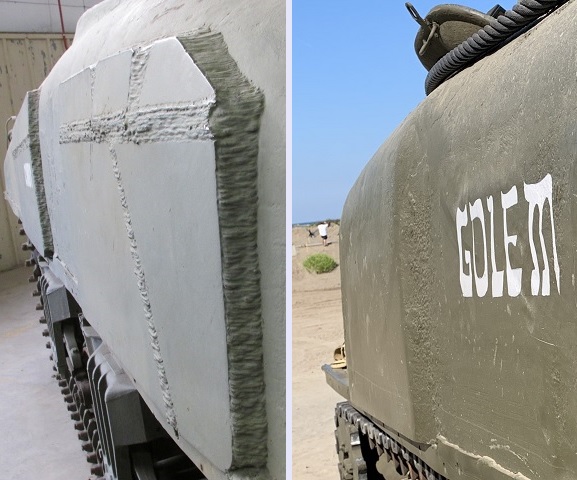
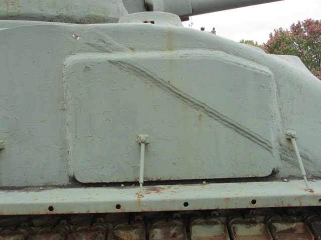
The applique armor panels attached to cast hull tanks, as seen on the left, had to be cut into pieces that were individually welded to the hull: Attaching the large flat plates to the contoured surface would otherwise have been problematic. Late in production, as seen on the right, the hull casting was changed so that the armor was increased in the areas protected by the applique plates. The armor between the two enhanced portions on the right side was ~2" (5cm) thick, as it did not slope completely down to the original 1.5" (3.8cm) thickness. Note the modification necessary in the sandshield attachment along the bottom of the sponson.

Tool stowage was altered on Canadian-produced tanks. Compared to the vehicles above, the strap for the shovel blade was at the front, and the track tension adjusting wrench and sledgehammer were stowed above the shovel instead of on the hull rear. Additional footman loops are welded to the hull left side as well.
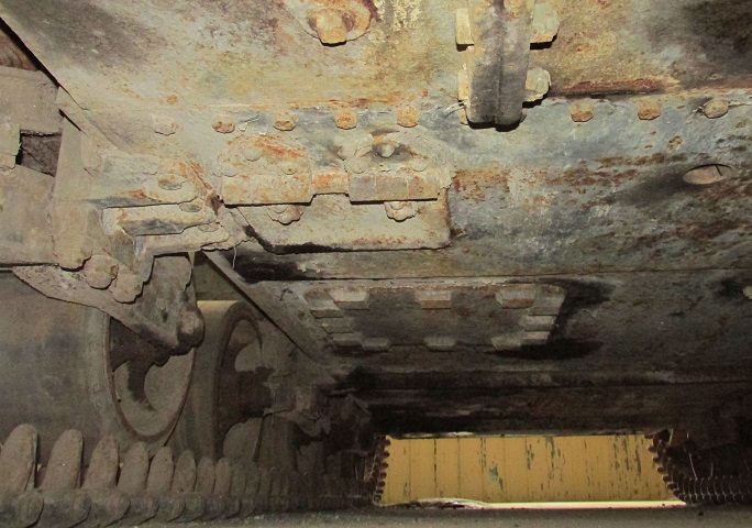
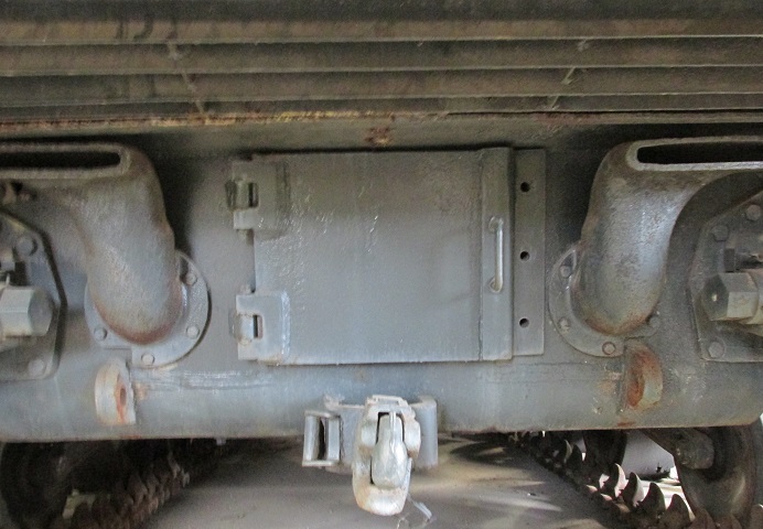
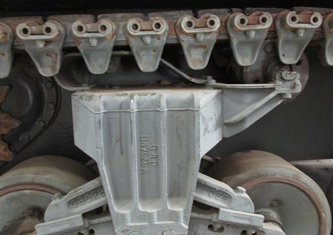
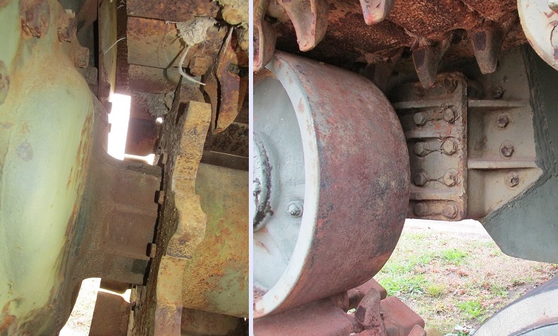
The assistant driver in the Grizzly was given an additional hatch in order to attach the indigenous Snake mine-clearing line charge. In this image, the joint for the right and center sections of the final drive and differential cover can be seen at the top center, and the large hull escape hatch is visible in the center of this image. The smaller hatch for the Snake attachment is forward of the hull escape hatch, right next to the attachment point of the forward suspension bogie on the left of the picture.
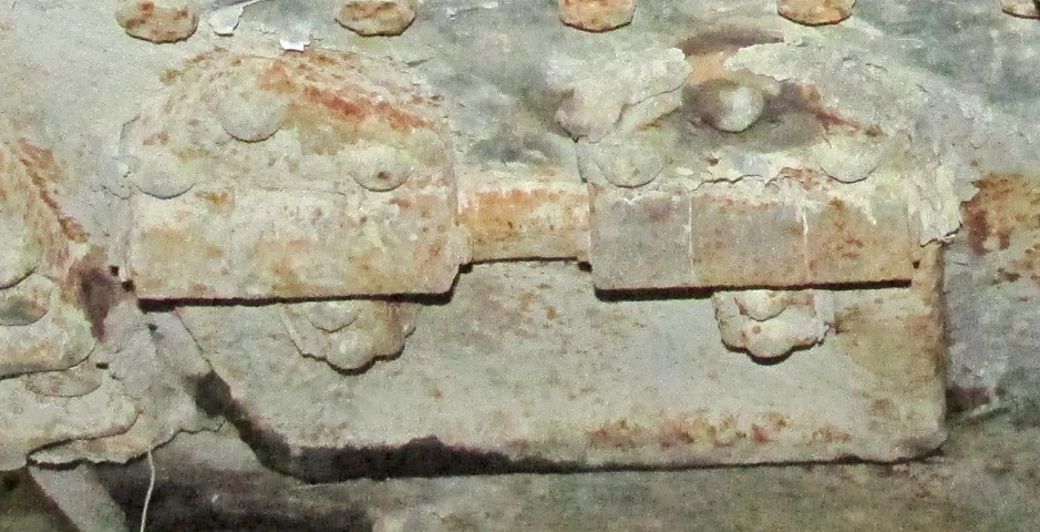
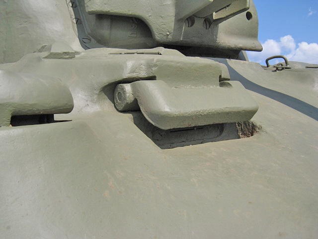
The smaller hatch is the focus of this image. The hatch featured two hinges to the front, which were each attached to the hull with three rivets in a triangular orientation. The line of bolts running across the top of the image secured the final drive and differential cover.
This is a very early M4A2 produced by the Fisher Tank Arsenal. It retains the early suspension bogies with the top-mounted return roller, and the twin driver's machine guns are mounted. These were eliminated before the first M4A2 was accepted, but production had already begun at Fisher before the change. The smooth rubber T51 tracks are readily evident on this tank, as is the bolted three-piece final drive and differential housing at the front of the hull. This M4A2 has the 56° glacis with early drivers' direct vision slots, and weld lines can be made out around the individual plates. There is an antenna base next to the assistant driver's position above the lifting eye, and the siren is mounted on the driver's fender. The tank's coaxial machine gun emerges from the aperture to the 75mm gun's left, and the M34 gun mount did not feature a gunner's telescope. Interestingly, in contrast to the coaxial and driver's machine guns, the bow machine gun is absent. (Picture taken June 1942 by Alfred T. Palmer; available from the Library of Congress.)
The fixed bow machine guns are absent on this tank, but the early-type suspension and the gun mount M34 remain. Note that these early-production features are combined with a single-piece final drive and differential cover, which first appeared in April 1942. (Picture from TM 9-731B Medium Tank M4A2.)
This side angle provides a better view of the early suspension bogies. (Picture from TM 9-731B Medium Tank M4A2.)
The layout of the rear of the M4A2 is shown here. The rear plate reaches below the sponsons, and bolts form a "T" on the rear plate. The exhaust deflector is below the rear plate between the idler wheels, and the track adjusting wrench is stowed on the rear plate. The heavy-duty type suspension with the rearward-mounted support roller is fitted. (Picture from TM 9-731B Medium Tank M4A2.)
Seen from above, note the engine grille doors behind the turret are approximately as wide as the turret bustle; similar grilles on the M4A3 ran all the way to the sponsons. Ventilating blowers can be seen outboard of the drivers' hatches, on the turret roof, and to the right rear of the turret. The turret lacks a hatch for the loader, as this was not introduced until October 1943. Mounts for two radio antennas are present in the turret bustle, and a third can be seen outboard of the bow machine gun. (Picture from TM 9-731B Medium Tank M4A2.)
The M4A2's rear deck fixtures are illustrated here. Later in production, a seventh filler cover similar to the six already present was added directly behind the engine grille doors. This protected an engine oil gauge added after improvements to the engine lubrication system that reduced particulate levels and increased cooling. The hull rear plate on this tank features six bolts running along its top to fasten the rear engine deck plate, but M4A2s could also be seen with eleven bolts across the upper rear hull. Also note the different grouser compartment covers from the M4A1 above as well as the open turret pistol port. (Picture from TM 9-731B Medium Tank M4A2.)
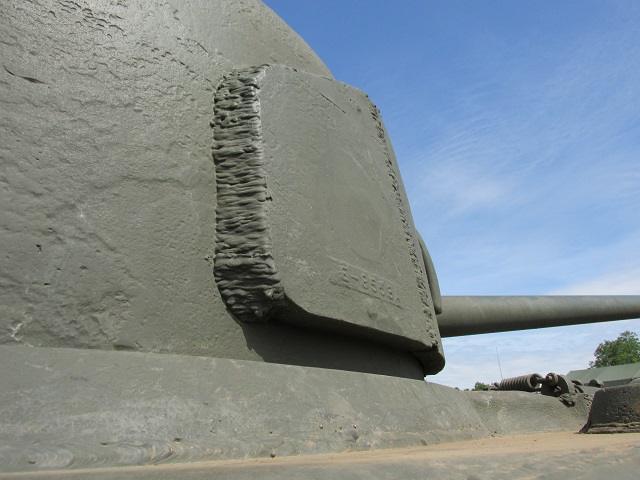
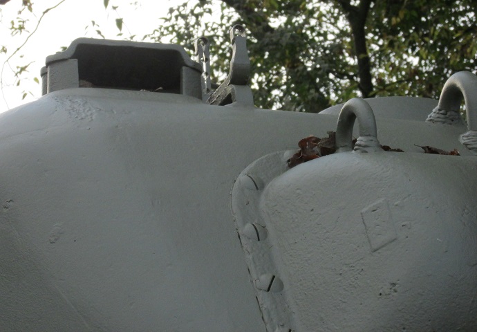
The engine deck and grilles are highlighted in these images. Note the cast rear splash guard for the turret ring attached with nine bolts, which contrasts to the earlier welded design secured with six bolts in the image above. The cast guard was also found with either five or six bolts fastening it to the hull. The turret overhang visible in the right image is due to a stowage box attached to the turret rear like those found on British 17 pounder-armed tanks.
A cross-sectional view of the M4A2 is provided in this image. The turret weighed 9,090lb (4,120kg) with the 75mm gun installed, and the power train unit composed of the transmission, differential, final drives, sprocket, and hug assemblies weighed 8,035lb (3,640kg); this lighter weight than the one given for the M4A1's transmission and final drive assembly presumably reflects the thinner, three-piece unit instead of the thicker one-piece casting. (Picture from TM 9-731B Medium Tank M4A2.)
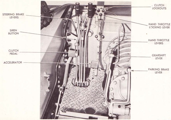
The driver's position is shown here with his seat removed for clarity. Each engine had its own hand throttle lever, and above these each engine had a pull-out button for locking out its clutch. The two clutches operated simultaneously when the clutch pedal was pressed, but locking out the clutch of one engine would enable the tank to operate on one engine if needed. (Picture from TM 9-731B Medium Tank M4A2.)
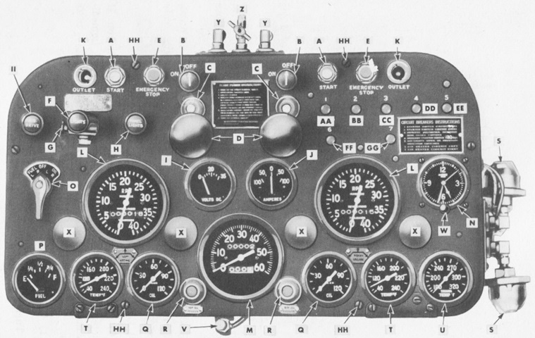
The driver's instrument panel is labeled in this image. A. Starter switch. B. Air heater switch. C. Air heater indicator light. D. Air heater fuel pump. E. Emergency stop switch. F. Driving light switch. G. Blackout light button. H. Panel light switch. I. Voltmeter. J. Ammeter. K. Accessory outlet. L. Engine tachometer. M. Speedometer. N. Clock. O. Tank gage control switch. P. Fuel and lube tank gage. Q. Engine oil pressure gage. R. Low oil pressure indicator. S. Low oil pressure indicator light switch. T. Engine temperature gage. U. Transmission oil temperature gage. V. Speedometer trip mileage reset. W. Clock wind and set. X. Instrument light bulb cover. Y. Air heater fuel pump outlet line. Z. Air heater fuel pump inlet line, with shut-off. AA. Circuit breaker (LC engine starter circuit). BB. Circuit breaker (LA engine starter circuit). CC. Circuit breaker (outlet socket, voltmeter, resistor, tank gage switch and tank unit circuits). DD. Circuit breaker (auxiliary starter switch circuits). EE. Circuit breaker (hull, stop, low oil, blackout, and driving lamps, and siren, circuits). FF. Circuit breaker (LC engine air heater circuit). GG. Circuit breaker (LA engine air heater circuit). HH. Panel face plate attaching screw. II. Blackout driving light switch. (Picture from Model 6046 Series 71 Twin 6 Cylinder Diesel Engine Maintenance Manual.)
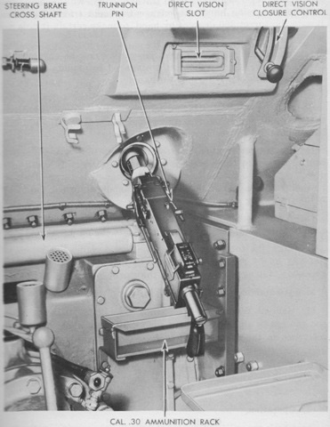
The assistant driver had no aiming device on his machine gun besides walking fire onto a target using tracers or impacts. The control for the direct vision slot cover is mounted to the right of the slot. A thick glass pane--absent in this case--could be mounted in the frame around the vision slot to protect against fragments or bullet splash. The opening of the antenna mount can also be seen in the sponson to the right. (Picture from TM 9-731B Medium Tank M4A2.)
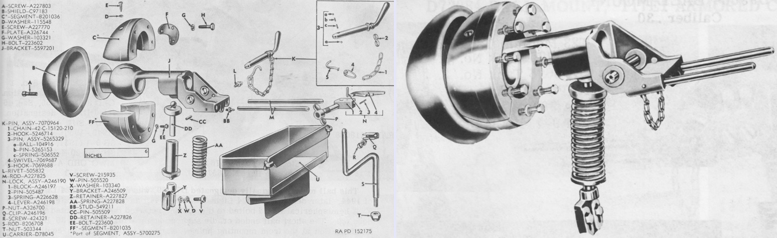
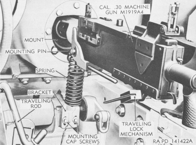
Exploded and assembled views of the caliber .30 ball mount 6551070 are shown on the left and right, respectively. An ammunition box M1 was attached to the mount, and the ammunition belt was inserted directly into the gun; no feed chute was used. The rods at the rear carried a spent case collection bag. The equilibrator spring was attached to the tank hull, and a travel lock could be installed in any of several positions. Plate F in the exploded diagram was a limiter to prevent the machine gun from striking the tank. Ball mount D51070 was a similar earlier type whose housing segments were not interchangeable with 6551070. (Pictures from Weapon Mounts for Secondary Armament.)
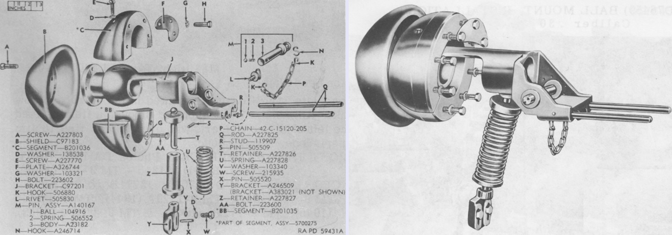
Similar views of the ball mount 7008929 are seen here. The mount was previously designated as 7387770, and as mount D82255B when it omitted the limit plate A326744. When the spring support bracket A383021 was used instead of the A246509 depicted in the image, the mount was designated 7387769. Similarly, mount D82255A omitted the limit plate with this spring support bracket. (Pictures from Weapon Mounts for Secondary Armament.)
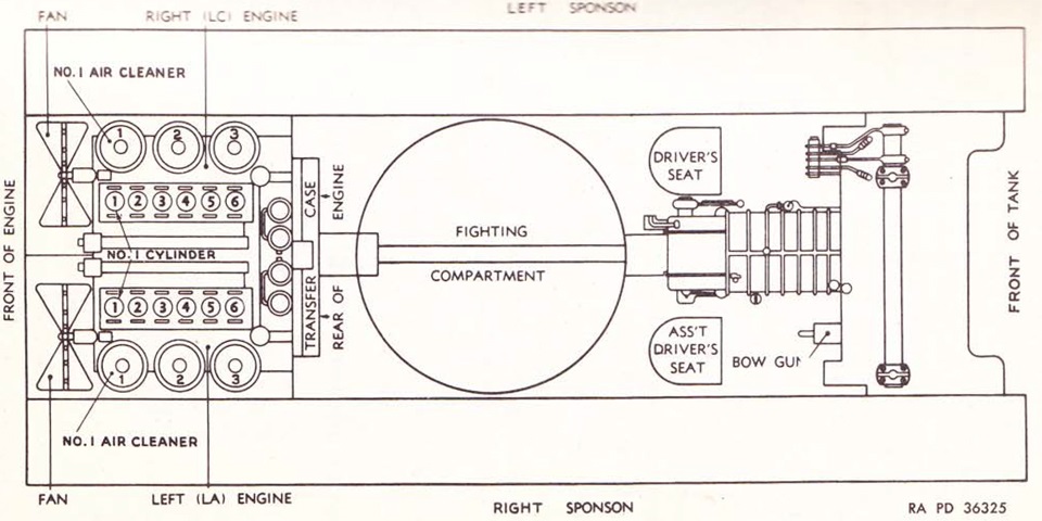
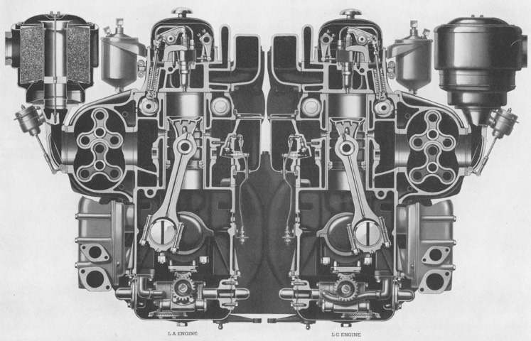
Since, when mounted in most vehicles and watercraft, the fan end of the 6-71 was considered the front, this nomenclature was retained even though the fans faced the rear of the tank. Similarly, the engines were considered "right" or "left" based on this orientation. The left engine was designated LA, while the right was called LC. A mnemonic suggested by the technical manual to help alleviate the inevitable confusion was to remember that the LA engine was considered the "laft" engine. (Picture from TM 9-731B Medium Tank M4A2.)
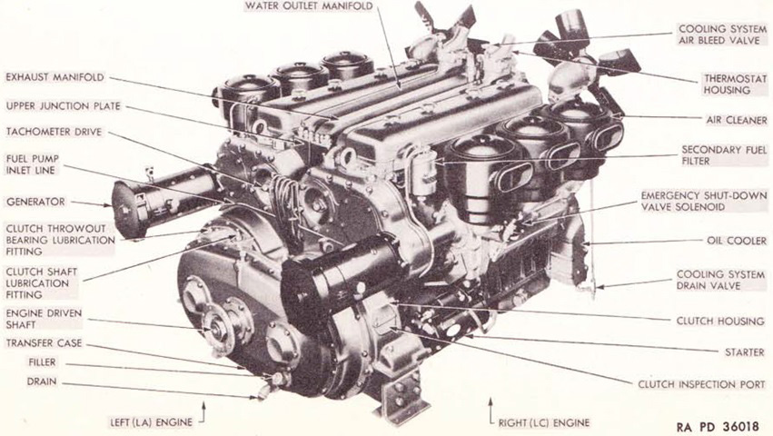
The 6046 used in the M4A2 was equipped with two generators and voltage and current regulators, as opposed to the single one of each found in the M3A3 and M3A5. Other changes included a total of four lubricating oil filters used in the M4A2, and its rear engine support brackets were longer with relocated mounting holes to mesh with the new tank's engine compartment. The stamped five-blade fans are present, and the M4A2 also used the 1:1.37 power transfer unit gearing and larger propeller shaft found on late M3A3s and M3A5s. (Picture from TM 9-731B Medium Tank M4A2.)
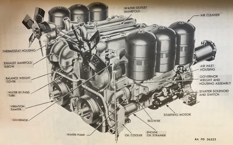
The fan side of the engine is seen here. (Picture from TM 9-731B Medium Tank M4A2.)
A side cross-section is provided in this picture. (Picture from Model 6046 Series 71 Twin 6 Cylinder Diesel Engine Maintenance Manual.)
An end elevation cross-section is drawn here. (Picture from Model 6046 Series 71 Twin 6 Cylinder Diesel Engine Maintenance Manual.)
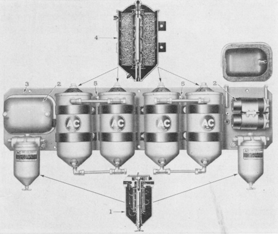
The accessory panel used in the M4A2 featured two more lubricating oil filters and was therefore rearranged from that found in the M3A3 and M3A5. 1. Primary fuel filter. 2. Heater coil box. 3. Filter panel. 4. Lubricating oil filters. 5. Auxiliary starting switch. (Picture from Model 6046 Series 71 Twin 6 Cylinder Diesel Engine Maintenance Manual.)
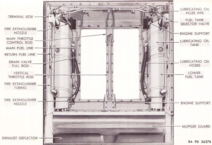
The engine compartment is shown here with the power unit removed. (Picture from TM 9-731B Medium Tank M4A2.)
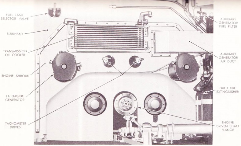
The fighting compartment side of the engine shroud is seen in this picture. (Picture from TM 9-731B Medium Tank M4A2.)
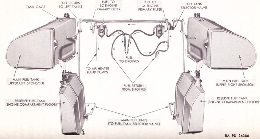
The fuel system was constantly pumping fuel at a maximum rate of 40gal/hr (150L/hr). One or both engines could use either the right or left set of tanks, but not both right and left at the same time. Excess fuel was returned to the set of tanks from which it came. (Picture from TM 9-731B Medium Tank M4A2.)
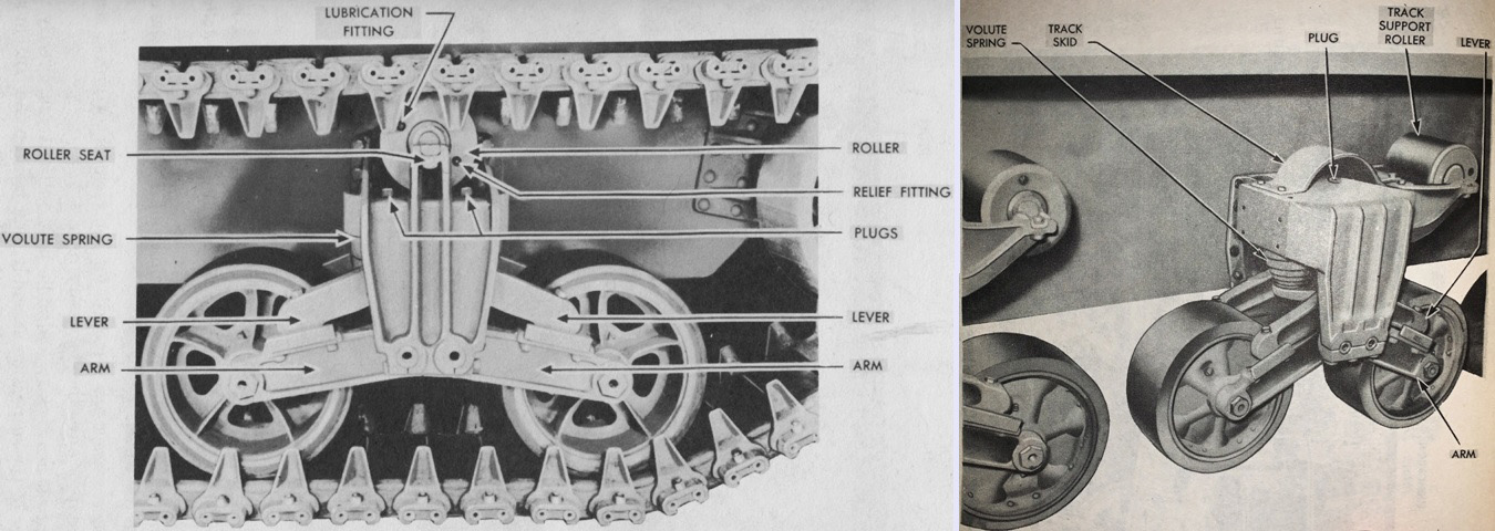
The early suspension bogie on the left can be compared with the heavy-duty type on the right. Note the shape of the track skid: later skids would extend past the front of the bogie bracket. (Picture from TM 9-731B Medium Tank M4A2.)
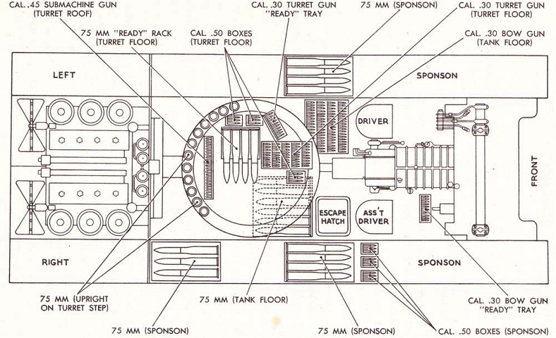
Ammunition stowage is detailed here. The need for the wet ammunition restowage that premiered in 1944 can be seen, as there was plentiful main gun ammunition behind the vulnerable sponson armor. (Picture from TM 9-731B Medium Tank M4A2.)
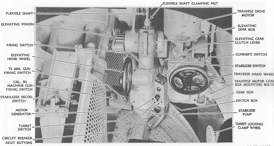
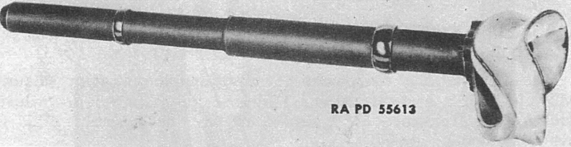
The gyrostabilizer control and gear boxes are shown on the left. The stabilizer was to be used only when the tank was in motion, and to protect the batteries the auxiliary generator was to be run while the stabilizer or power traversing mechanisms were being used. The tank's speed was to be held as constant as possible and the engine was to be run at full governed speed when the stabilizer was on. Lower gears were to be used if lower speeds were desired while still running the engine at its maximum rpm. The gyrostabilizer connected to the gun mount via the hydraulic cylinder shown on the right. (Picture from TM 9-731B Medium Tank M4A2.)
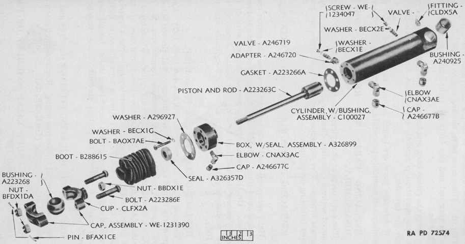
An exploded view of the stabilizer's cylinder and piston assembly is diagrammed in this picture. Compared to the previous image, this cylinder is of a later type fitted with a boot to protect the exposed portion of the rod. The piston rod was attached to the gun, while the cylinder was fastened to the turret. Two ⅜" (.953cm) oil lines from the oil pump allowed pressure to act on both sides of the piston. A ¼" (.64cm) line returned oil to the oil pump that leaked by the piston rod into the stuffing box. Very early in production, two bleeder valves were introduced to allow the removal of air without cracking the oil lines. The cylinder could be sealed with an oil seal, as illustrated here, or with chevron-type packing, which required an additional guide for the rod. (Picture from TM 9-1334 Ordnance Maintenance--Stabilizers.)
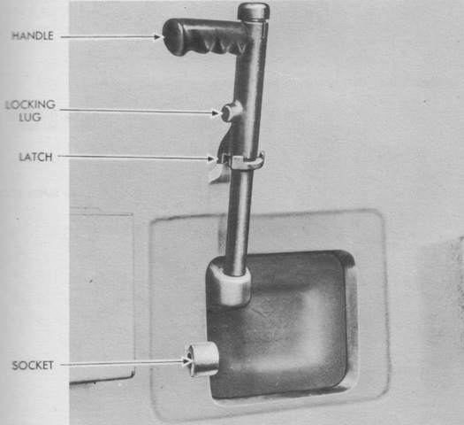
The turret pistol port is shown here from the inside. It could be locked in the closed or open positions by turning the handle to release or engage the latch or lug/socket. (Picture from TM 9-731B Medium Tank M4A2.)
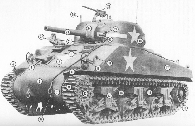
This early tank features the M34 gun mount without the armor for the coaxial machine gun. Also note the .30cal machine gun on the turret roof; the Ordnance Committee replaced the .50cal machine gun with a .30cal machine gun in September 1942, but this decision was reversed in April 1943. 1. Direct vision devices. 2. Front slope plate. 3. .30 cal bow machine gun. 4. Front mudguard. 5. Differential housing. 6. Towing shackle and cable. 7. Final drive housing. 8. Siren. 9. Headlight. 10. Lifting eye, hull. 11. Track. 12. Sprocket. 13. Bogie suspension unit. 14. Support roller bracket. 15. Skid. 16. Idler. 17. Sponson. 18. Turret. 19. .30 cal coaxial machine gun. 20. Driver's hatch. 21. Periscopes. 22. Bog [bow gunner] hatch. 23. 75-mm gun. 24. 75-mm gun rotor shield. 25. Sight, front turret. 26. .30 cal AA machine gun. (Picture from Medium Tank Installations.)
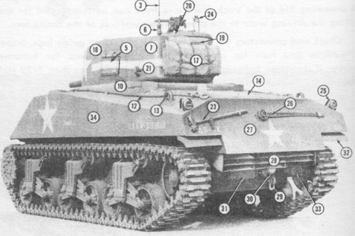
The rear of an early-production model is shown here. 3. Antenna. 5. Pistol port. 6. Antenna base. 7. Turret bulge. 10. Bullet splash plate. 12. Tow cable. 13. Lifting eye, hull. 14. Top engine compartment doors. 17. Tarpaulin. 18. Turret. 19. Antenna base mount. 20. Turret hatch. 21. Lifting eye, turret. 23. Pioneer tools. 24. AA machine gun bracket. 25. Stop, tail, and BO [blackout] lights. 26. Track adjusting wrench. 27. Bustle. 28. Air deflector. 29. Towing shackle. 30. Exhaust manifold. 31. Rear engine compartment doors. 32. Mud guard. 33. Idler bracket. (Picture from Medium Tank Installations.)
The shape of the turret can be seen here on this early production example with the gun mount M34 and no loader's hatch. Note the width of the engine deck grille doors. The lower vertical fuel tank filler cap is mislabeled; it actually is pointing to an antenna mount. (Picture from TM 9-7018 Medium Tank M4A3.)
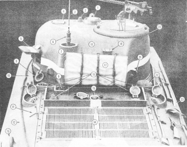
The engine deck of an early-production model is labeled in this diagram. 1. Ventilator. 2. Spotlight mount. 3. Antenna. 4. Loader's periscope mount. 5. Pistol port. 6. Antenna base. 7. Turret bulge. 8. Fire extinguisher controls. 9. Fuel tank cap, aux generator. 10. Bullet splash plate. 11. Fuel tank cap pin. 12. Tow cable. 13. Lifting eye, hull. 14. Top engine compartment doors. 15. Engine coolant filler cap. 16. Fuel filler caps. 17. Tarpaulin. 18. Turret. 19. Antenna base mount. 20. Turret hatch. 21. Lifting eye, turret. 22. Ventilator. 23. Pioneer tools. (Picture from Medium Tank Installations.)
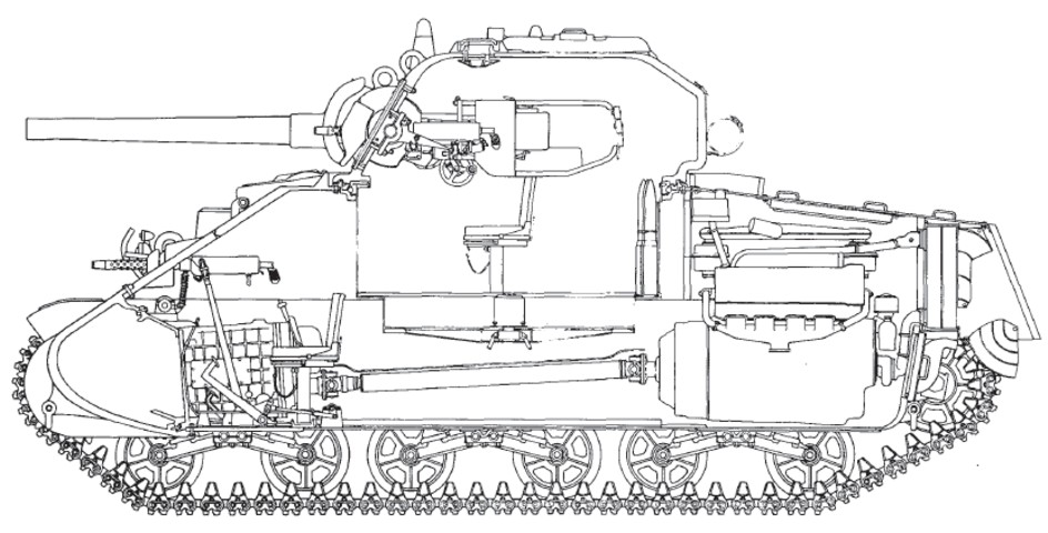
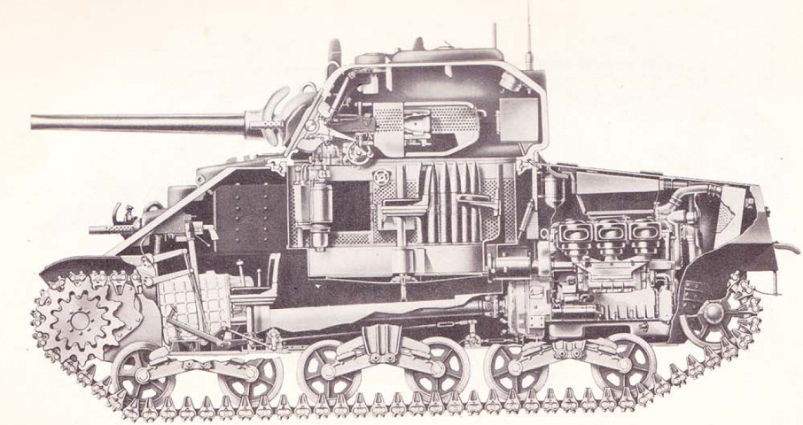
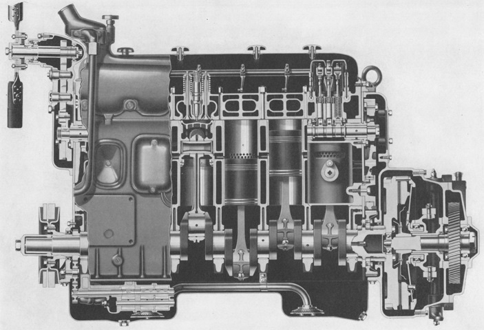
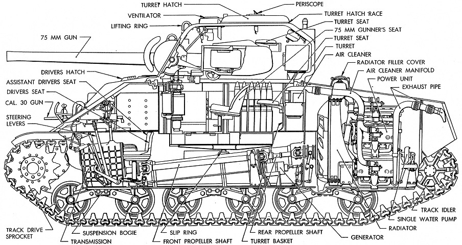
This sectionalized view shows the interior arrangement of the tank. Note the propeller shaft running underneath the turret from the engine to the front-mounted transmission. This feature, common to all Shermans, had much to do with their height, especially since tanks with taller radial engines were designed first. (Picture from TM 9-759 Medium Tank M4A3.)
This early-production M4A3 features the drivers' direct vision slots and lacks the applique armor later added over the hull ammunition racks and the gunner's controls on the turret. It also has the gun mount M34 which used a periscopic primary sight; since no telescope was fitted, the armor flap on the right side of the M34A1's rotor shield is absent.
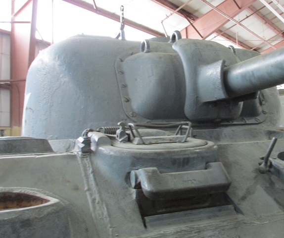
Since the gun mount M34 did not feature a telescope, the right side of its gun shield was solid. If the coaxial machine gun armor was fitted, it would attach to the machine gun barrel itself. Since the machine gun is missing on this tank, the armor is not present even if it had been originally mounted. Weld marks across the glacis and between the drivers' hoods show how the 56° glacis was built up from several plates.
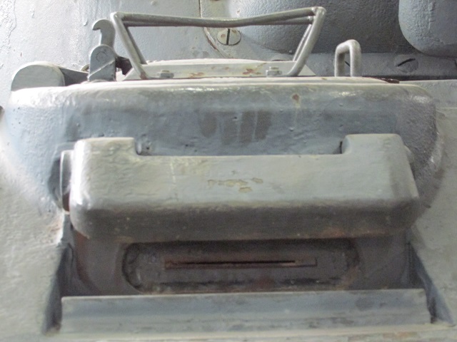
The armored cover for the assistant driver's direct vision slot is raised on this example.
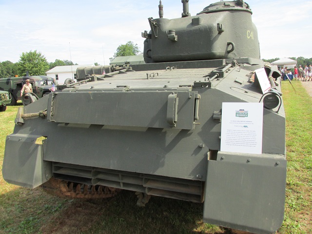
The rear of this tank illustrates how the rear armor plate comes below the sponson line (below the attachment points for the sandshields), and the exhaust deflector is fitted below the rear overhang. Stowage brackets for the .50cal machine gun are present on the turret bustle. A folding blanket rack for the crew is mounted on the rear hull plate, and brackets for stowing cleaning rods for the 75mm gun are visible on its underside. This tank has been modified in a post-World War II rebuild program to incorporate later features, including the torsion bars attached to the engine grilles on the rear deck. These grille doors would have had simple hinges originally.
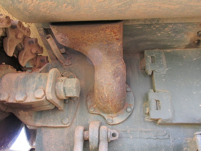
The engine exhaust deflector is highlighted in the left image. This type of was of sheet metal and was hinged to allow access underneath. A handle was designed into the deflector to ease raising. Further details of the blanket rack, including hinges and a better look at the gun cleaning rod stowage brackets, can also be seen. The left-side exhaust pipe for the main engine is detailed on the right. Note that the collar is shaped to clear the towing shackle below on the hull. The small pipe to the left of the engine exhaust is the exhaust for the auxiliary generator.
The shape of the engine exhaust pipes can be better seen on this machine with the deflector out of the way.
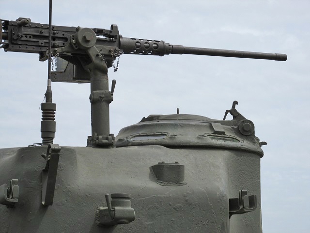
Details of the commander's cupola and .50cal machine gun mount and stowage brackets are revealed in this image. The earlier commander's split hatch had an integral mount for the .50cal machine gun, but when the vision cupola was installed a hinged mount was added to the roof which was able to be folded down when not in use. An antenna is present in the left antenna mount. There is another smaller square antenna mount visible on the right side of the turret bustle. This mount would be in use on British tanks, as their No. 19 radio used two antennas.
The commander's split hatch labeled here can be contrasted with the vision cupola. 1. Door locking handle. 2. Pad, rubber. 3. Machine gun bracket. 4. Sight, front turret. 5. Ventilator. 6. Turret hatch ring. 7. Periscope mount. 8. Lubrication fitting. 9. Lock. 10. Lug. 11. Machine gun mount. 12. AA .30 cal machine gun. (Picture from Medium Tank Installations.)
The applique armor welded to the front of the turret is highlighted in this picture. The turret armor was reduced to 2" (5.1cm) at this spot to make room for the gunner's controls, and these applique plates brought the thickness back to a nominal 3" (7.6cm). Note that the plate is actually two pieces of armor welded together due to the curvature of the turret.
This 56° glacis tank was built with drivers' hoods with periscopes instead of direct vision slots. Applique armor was added to the hoods in a manner similar to that of the hull sides and turret. The mount for attaching a canvas dust cover around the hull machine gun had to be re-welded to the applique plate. This tank is also fitted with a gun travel lock.
The front applique armor plates were 1.5" (3.8cm) thick, and welded at the top and bottom. The hull antenna mount and a lifting hook are in the foreground.
The locations of the extra set of periscopes for the drivers is better illustrated in this image. Also visible are the spring and hold open catches for the driver's hatch door. The armor pieces protecting the sides of the base of the 75mm gun were not seen on the earliest M34 rotor shields.
Both periscopes can be seen in this example, as well as the hatch's internal locking mechanism in the upper left corner.
This late M34 mount was modified to accept the telescopic sight also found in the M34A1 mount, and a slot was cut into the gun shield to accommodate it. Additional armor was welded to the right side of the rotor shield to protect the telescope, but the left side of the mount was unmodified. The right side gun shield lifting eye was deleted in favor of a threaded hole. The armor for the coaxial machine gun is missing on this tank.
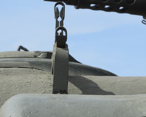
This more complex vane sight replaced the earlier simple device seen on the M4A1 above.
The gunner's periscope was initially protected only by sheet metal, but an armored cover was designed and implemented.
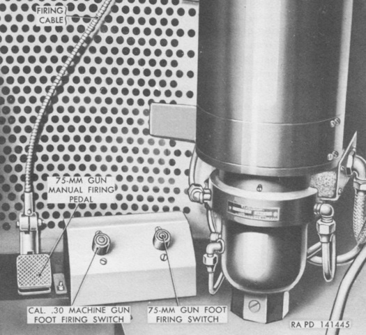
Besides the hand triggers, the gunner was also provided with electrical foot triggers for both the 75mm gun and coaxial machine gun. A foot pedal for manually firing the 75mm gun was beside the electrical triggers. (Picture from TM 9-7018 Medium Tank M4A3.)
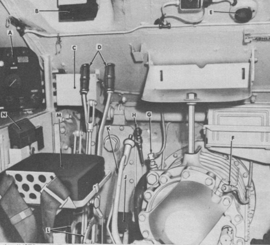
The driver's position is labeled in this picture. His seat back has been removed for clarity. A. Instrument panel. B. Driver's periscope. C. Front junction box. D. Steering brake levers. E. Dome light. F. Speedometer driver shaft adapter. G. Transmission oil temperature gage switch. H. Hand throttle. J. Accelerator pedal. K. Gear shift lever. L. Brake lock quadrant. M. Driver's seat. N. Spare periscope. (Picture from TM 9-7018 Medium Tank M4A3.)
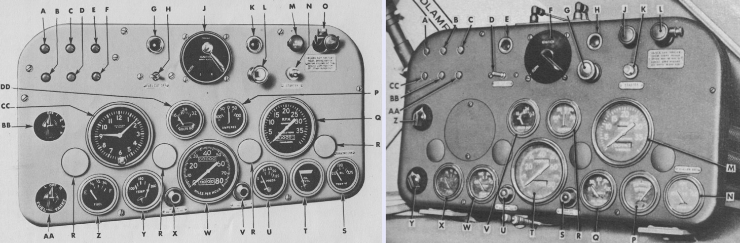
Two instrument panels are detailed here, one with a clock and one without. The legend for the left image is: A. Right-hand utility outlet circuit breaker button. B. Siren circuit breaker button. C. Left-hand utility outlet circuit breaker button. D. Fuel cut-off and hull lamps circuit breaker button. E. Blackout drive switch circuit breaker button. F. Circuit breaker button for panel lights, fuel gage, water temperature gage, low oil pressure light, water boil signal light, oil level gage, voltmeter and transmission oil temperature gages. G. Utility outlet. H. Fuel cut-out switch. J. Ignition switch. K. Utility outlet. L. Engine priming pump. M. Blackout driving light switch. N. Starter switch. O. Light control switch. P. Ammeter. Q. Tachometer. R. Instrument panel light cover. S. Transmission oil temperature gage. T. Oil level gage. U. Oil pressure gage. V. Low oil pressure signal. W. Speedometer. X. Engine boil signal. Y. Engine temperature gage. Z. Fuel level gage. AA. Fuel selector switch. BB. Panel light rheostat switch. CC. Clock. DD. Voltmeter.
The legend for the right image is: A. Right-hand utility outlet circuit breaker. B. Left-hand utility outlet circuit breaker. C. Blackout drive switch circuit breaker. D. Fuel cut-off switch. E. Utility outlet. F. Ignition switch. G. Primer pump. H. Utility outlet. J. Blackout driving light switch. K. Starter switch. L. Main light switch. M. Tachometer. N. Transmission oil temperature gage. P. Oil level gage. Q. Oil pressure gage. R. Ammeter. S. Low oil pressure warning light. T. Speedometer. U. Water high temperature warning light. V. Voltmeter (not used). W. Engine water temperature gage. X. Fuel gage. Y. Fuel tank selector switch. Z. Panel light rheostat switch. AA. Blackout drive light switch circuit breaker. BB. Instrument panel circuit breaker. CC. Horn circuit breaker. (Picture from TM 9-759 Tank, Medium, M4A3 and TM 9-7018 Medium Tank M4A3.)
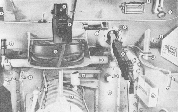
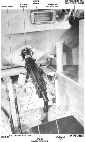
The assistant driver's position in a direct-vision tank is labeled here. The assistant driver had no controls for driving the tank. 1. Direct vision device handle. 2. Direct vision device. 3. Compass light switch. 4. Direct vision device. 5. Steering lever. 6. Compass. 7. Flashlight. 8. Ball mount. 9. Headlight lock. 10. Spare parts, gun. 11. MG rear fixed mount. 12. .30 cal machine gun. 13. Steering control cross-shaft. 14. Hood, driver's hatch. 15. Plug, brake band cover. 16. Throttle. 17. Gear shift lever. 18. Transmission. 19. Breather, transmission. 20. Plug, brake band cover. 21. Brake band cover. 22. Spare periscope holder. (Picture from Medium Tank Installations.)
Details of the bow machine gun mount are shown in this picture. (Picture from TM 9-7018 Medium Tank M4A3.)
This cutaway turret shows the location of the 2" smoke mortar as well as the loader's periscope. The coaxial machine gun is obvious, and the radio is visible in the rear of the turret. A submachine gun is stowed above the radio.
The bottom of the gunner's seat is visible in this picture, along with the turret ring. The underside of the white-painted gearbox for the hydraulic traversing mechanism can be seen along the turret race, with the rusty shifter lever attached to its underside. The green box houses the turret master switch and reset buttons, and the hydraulic traverse control handle can be seen above the coiled yellow cord.
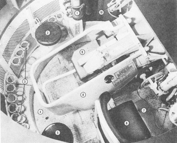
A view into the turret interior is provided here. 1. Portable fire extinguisher. 2. Loader's seat. 3. 75-mm ammunition ready clips. 4. Trap door. 5. Tank commander's seat. 6. Gunner's seat. 7. Gunner's controls. 8. Recoil guard. 9. 75-mm breech. 10. .30 cal coaxial MG. (Picture from Medium Tank Installations.)
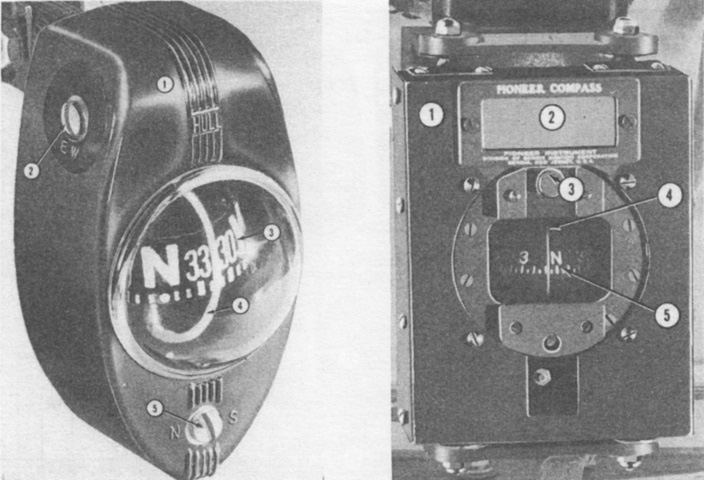
Both the tank commander and driver were provided with a compass. The tank commander's was manufactured by the Hull Manufacturing Company, and the driver's was an aviation type by the Pioneer Instrument Company.
The Hull compass is on the left: 1. "Hull" compass. 2. East-west compensating screw. 3. Compass card. 4. Index reference. 5. North-south compensating screw.
The Pioneer compass is on the right. 1. "Pioneer" compass. 2. Magnet compensator drawer. 3. Compensator adjusting screw cover plate. 4. Index reference. 5. Parallel magnet. (Picture from Medium Tank Installations.)
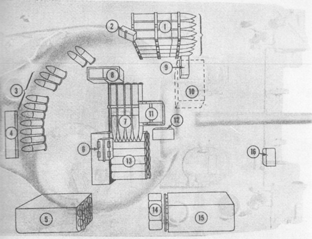
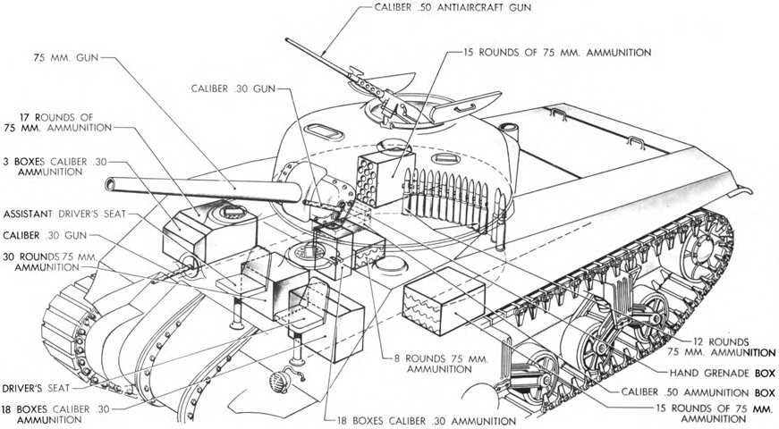
Ammunition stowage is sketched in this image. 1. 75-mm--15 rounds. 2. 2 smoke--2 thermite grenades. 3. 75-mm--12 rounds. 4. Cal .45--600 rounds. 5. 75-mm--15 rounds. 6. 8 grenades. 7. 75-mm--8 rounds. 8. Cal .50--100 rounds.* 9. Cal .30--250 rounds. 10. Cal .30--4500 rounds. 11. Cal .30--1740 rounds. 12. Cal .50--50 rounds.* 13. 75-mm--30 rounds. 14. Cal. 50--150 rounds.* 15. 75-mm--17 rounds. 16. Cal .30--250 rounds.
*If cal .50 machine gun installed as AA gun
75mm ammunition was to be removed from the racks in the following order: the ready racks on the turret floor, the racks in the forward right sponson, the racks under the turret floor, and finally the rear right sponson. Ammunition in the turret ready clips and in the left sponson were to be kept as a reserve for actions where loading speed was paramount. If possible as time permitted, the racks under the turret and in the rear right sponson were emptied to refill handier racks. (Picture from Medium Tank Installations.)
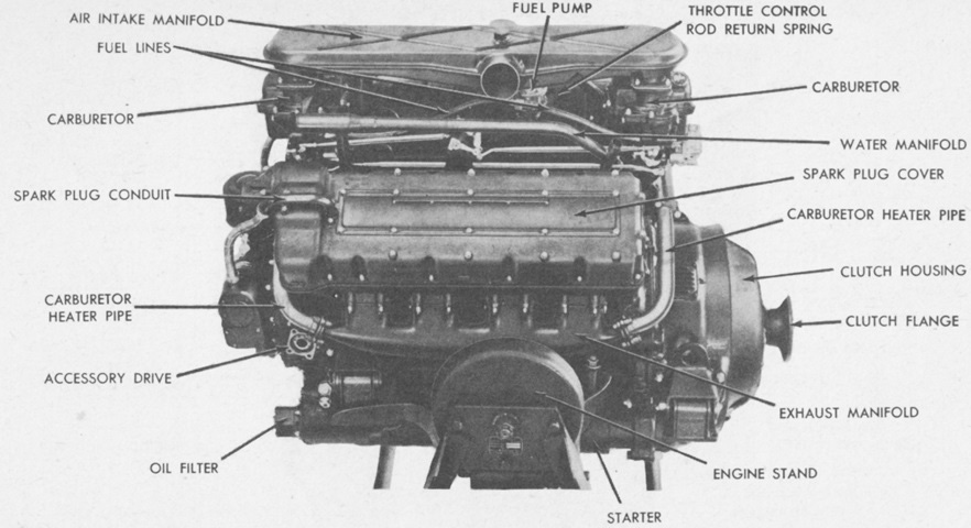
The right side of the Ford GAA engine is shown here. This became the US Army's preferred medium tank engine. Including the clutch, it was 59.02" (149.9cm) long, 33.25" (84.46cm) wide, and 47.78" (121.4cm) tall. It weighed 1,470lb (667kg) including the accessories. Prior to engine No. 2000, the oil pan lacked the scavenger pump feature found in later production, and the oil pressure and oil relief valve were found inside of the pan and were consequently unable to be accessed from the exterior. (Picture from TM 9-1731B Ordnance Maintenance--Ford Tank Engines (Models GAA, GAF, and GAN).)
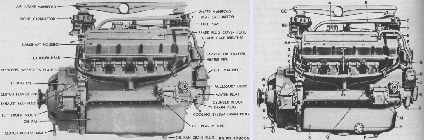
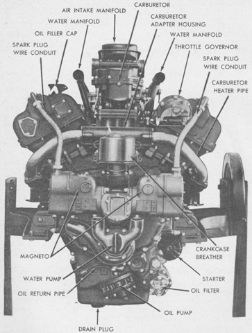
The left sides of early (left) and late (right) versions of the GAA can be contrasted. The legend for the right image is: A. Fuel pump. B. Water manifold. C. Carburetor assembly. D. Engine oil filler cap. E. Spark plug cover. F. Crankcase breather. G. Carburetor adapter-to-exhaust manifold tube. H. Magneto. J. Accessory drive shaft flange. K. Water pump. L. Water pump drain plug. M. Engine mount. N. Oil level gage sending unit cover. P. Oil pan drain plug. Q. Cylinder block drain plug. R. Oil pan. S. Clutch release fork. T. Engine mount. U. Exhaust manifold. V. Clutch main shaft flange. W. Lifting eye. X. Clutch housing vent cover and inspection plate. Y. Cylinder head. Z. Oil level gage. AA. Camshaft housing. BB. Carburetor. CC. Manifold. (Picture from TM 9-759 Tank, Medium, M4A3 and TM 9-7018 Medium Tank M4A3.)
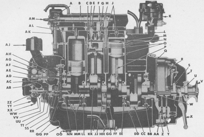
A longitudinal cross-section of an early engine is presented. A. Camshaft gear. B. Camshaft. C. Piston pin retainer. D. Piston pin. E. Valve spring. F. Push rod. G. Push rod guide. H. Valve. J. Cylinder head nuts. K. Carburetor. L. Carburetor adapter housing. M. Piston. N. Compression rings. O. Oil rings. P. Connecting rods. Q. Starter ring gear. R. Clutch pressure plate ass'y. S. Clutch release bearing. T. Clutch housing. U. Bearing, clutch mainshaft. V. Flange, clutch mainshaft. W. Clutch shaft pilot bearing. X. Clutch throw out arm. Y. Center drive plate. Z. Driven disks. AA. Flywheel. BB. Front main bearing. CC. Connecting rod bearing liner. DD. Oil pan baffle. EE. No. 4 main bearing. FF. Crank shaft. GG. Main bearing stud and nut. HH. Oil pump screen. JJ. No. 3 main bearing. KK. Main bearing liner. LL. No. 2 main bearing. MM. Crankshaft oil passage seals. NN. No. 1 main bearing. OO. Oil pain drain plug. PP. Oil pan. QQ. Crankshaft helical gear. RR. Helical driven gear and shaft, accessory drive. SS. Crankshaft worm gear. TT. Bearing. UU. Water pump driving quill. VV. Water pump bearings. WW. Water pump shaft. XX. Water pump drain plug. YY. Water pump housing. ZZ. Water pump seal. AB. Water pump impeller. AC. Bearing. AD. Magneto advance governor. AE. Magneto drive gear. AF. Magneto driven gear. AG. Accessory shaft bevel driven pinion. AH. Accessory shaft bevel driven gear. AJ. Crankcase breather. AK. Upper cam drive shaft. AL. Spark plug. AM. Tachometer drive. (Picture from TM 9-1731B Ordnance Maintenance--Ford Tank Engines (Models GAA, GAF, and GAN).)
The rear of the GAA is labeled in this picture. Bore and stroke were 5.4" (14cm) and 6" (15cm), respectively, for a displacement of 1,100in³ (18L); the compression ratio was 7.5:1. Cylinders were numbered 1 through 4 on each side, with 1 being the rear cylinder in each bank. Firing order was R-1, L-2, R-3, L-1, R-4, L-3, R-2, and L-4. (Picture from TM 9-1731B Ordnance Maintenance--Ford Tank Engines (Models GAA, GAF, and GAN).)
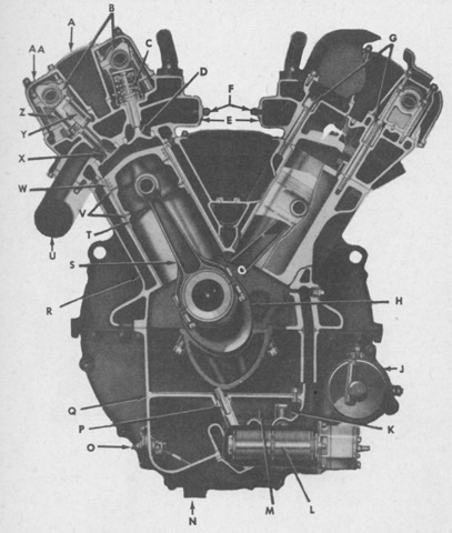
This cross-section of an early engine shows the valve and 60° piston arrangement. A. Spark plug cover. B. Camshafts. C. Valve springs. D. Intake valve. E. Intake manifolds. F. Primer nozzles. G. Cylinder head nuts. H. Crankshaft. J. Starter. K. Oil relief valve. L. Oil filter ass'y. M. Oil pan baffle. N. Oil drain plug. O. Oil gage unit. P. Oil pump shaft. Q. Oil pan. R. Block. S. Connecting rod. T. Piston. U. Exhaust manifold. V. Oil rings. W. Compression rings. X. Exhaust valves. Y. Push rod guide. Z. Push rods. AA. Camshaft housing. (Picture from TM 9-1731B Ordnance Maintenance--Ford Tank Engines (Models GAA, GAF, and GAN).)
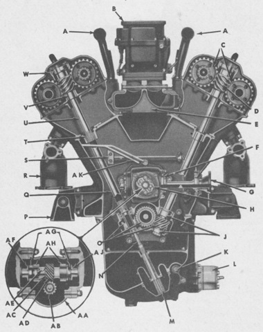
The cross-section of this early engine highlights the camshaft drive. A. Water outlet manifold. B. Carburetor. C. Camshaft gears. D. Camshaft drive gears. E. Carburetor adapter housing. F. Accessory shaft bearings. G. Accessory shaft drive flange. H. Magneto advance governor. J. Lower cam drive bearing. K. Oil pressure gage connection. L. Oil filter. M. Oil pump. N. Oil pump drive quill. O. Lower camshaft drive gears. P. Engine mounts. Q. Camshaft drive, lower shaft. R. Exhaust manifold. S. Oil pipe ass'y. T. Camshaft drive lower shaft bearing. U. Camshaft drive, upper shaft. V. Camshaft support bearing. W. Camshaft upper drive worm bearing. AA. Accessory cover. AB. Magneto drive gear. AC. Timing adjustment. AD. Magneto driven gear. AE. Key. AF. Magneto driven flange. AG. Driving flanges. AH. Magneto drive bearings. AJ. Magneto drive flange. (Picture from TM 9-1731B Ordnance Maintenance--Ford Tank Engines (Models GAA, GAF, and GAN).)
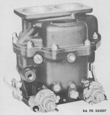
The GAA used two Stromberg NA-Y5G double-barrel downdraft carburetors. The NA-Y5G featured a throttle-controlled accelerating pump and a vacuum-controlled power jet. Each throttle barrel had a degasser incorporated into the idle system, which would shut off fuel supply when high manifold pressure was present during deceleration periods. The degasser was controlled by a spring-loaded diaphragm with the engine running, and an electric solenoid would shut off the fuel supply when the ignition was turned off. (Picture from TM 9-1826B Ordnance Maintenance--Carburetors (Stromberg).)
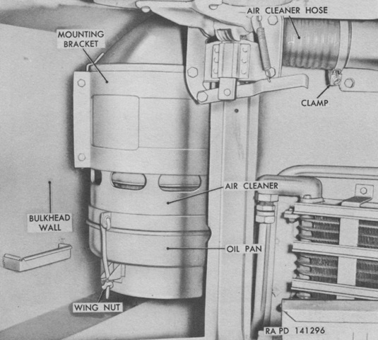
Initially, the M4A3's engine air cleaners were mounted at the rear of the fighting compartment. They were later moved to the engine compartment. (Picture from TM 9-7018 Medium Tank M4A3.)
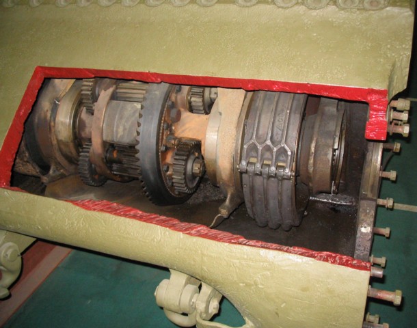
The final drive and differential cover has been cut away in this view. The steering brake can be seen outboard of the controlled differential gearing.
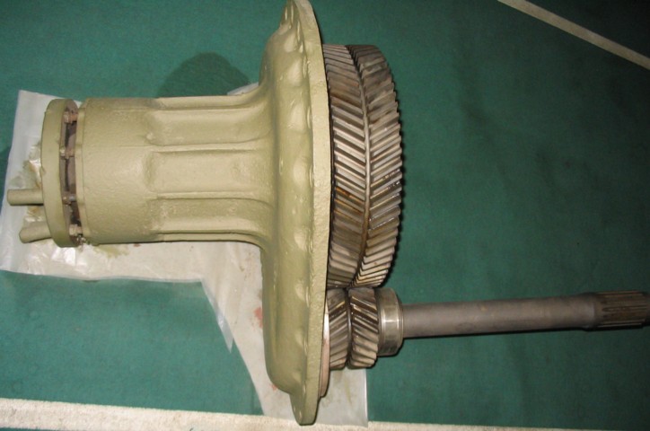
The right-hand final drive is shown here. The splined shaft would connect to the controlled differential, and the drive sprocket would attach to the hub at the opposite end.
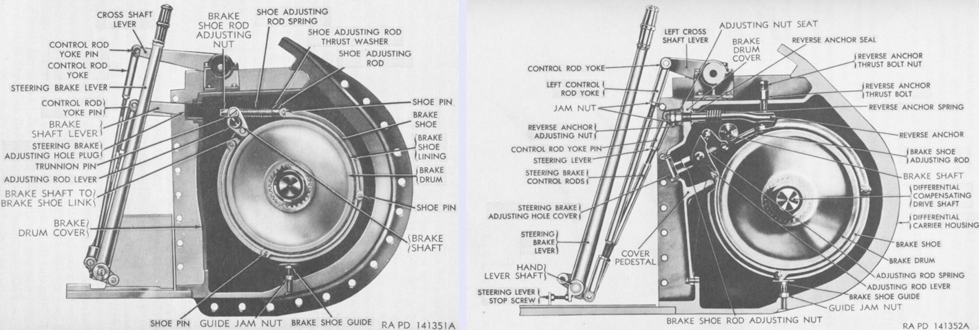
One of two designs of steering brakes could be found on the tank, both of which were three-shoe external contracting types. The single-anchor brake is shown on the left. The brake shaft in this design tightened the shoes on the drum and served as an anchor for the shoes to take the torque reaction of the system. The single-anchor brakes had adjusting screw plugs near the top center of the brake drum covers. When the steering lever was pulled to the rear, the control rods and brake shaft levers were pulled downward.
On the right, double-anchor steering brakes are shown in cross-section. In this design, two fixed anchors transferred the brake torque reaction directly to the brake housing instead of to the brake operating lever system, leading to less hand effort being needed to make a turn. The double-anchor brakes had reverse anchor adjusting nuts near the top of the brake drum covers, and the brake control rods were heavier than on the single anchor design. Also, the control rods and brake shaft levers were pushed upward when the steering levers were pulled to the rear. Either type of brake could be found in the three-piece and the round single-piece final drive and differential covers, but only the double-acting brakes were installed in sharp-nose single-piece covers. (Picture from TM 9-7018 Medium Tank M4A3.)
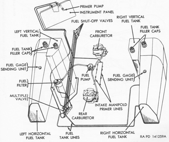
The fuel system is diagrammed in this sketch. A single fuel filter strained the fuel, and four shutoff valves were provided. (Picture from TM 9-7018 Medium Tank M4A3.)
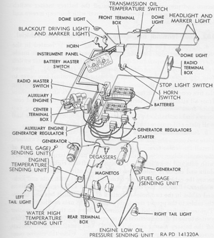
The battery and generator system was comprised of two generators, two batteries, two generator regulators, and the requisite wiring. The 12-volt wet cell storage batteries were connected in series to provide 24-volts of current, and were housed under the turret platform. (Picture from TM 9-7018 Medium Tank M4A3.)
The HRUH-28 auxiliary generator was provided with a muffler and fittings in the M4A3 and M4A4 instead of the duct found in other tanks. The assembly weighed 125lb (56.7kg) in this configuration. (Picture from TM 9-7018 Medium Tank M4A3.)
The suspension bogie on this early tank features a straight return roller arm. Steel tracks could cause severe wear to the track skids, so the return rollers were raised to help compensate. Until raised return roller arms made it into production, the return roller itself was raised a bit by the spacer placed between the roller and the mounting arm, as seen here. Note how the shape of the track skid has been changed from the earlier design so that it extends past the front of the bogie bracket.
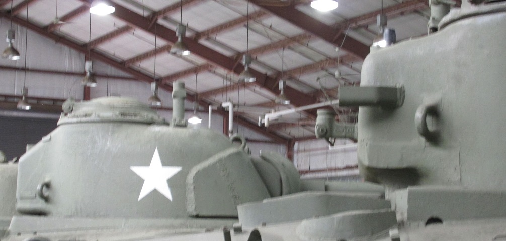
This picture illustrates the difference in the turret rear for tanks with the 56° glacis compared to later-production tanks with the 47° glacis and larger drivers' hatches. The turret in the background belongs to a 56°-glacis M4, and the radio bustle can be seen sloping downward from the roof. The tank in the foreground is an M4(105) with the 47° glacis, and its radio bustle protrudes at a much more horizontal angle which provides more clearance from the hull. This change was due to the taller hinges associated with the large drivers' hatches.
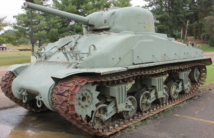
This tank is also fitted with the spaced out suspension seen on the M4A1E9 above, and also features the composite cast/welded hull. The border between the cast and welded portion of the hull is marked by a large weld, and the applique armor on this side follows the weld line.
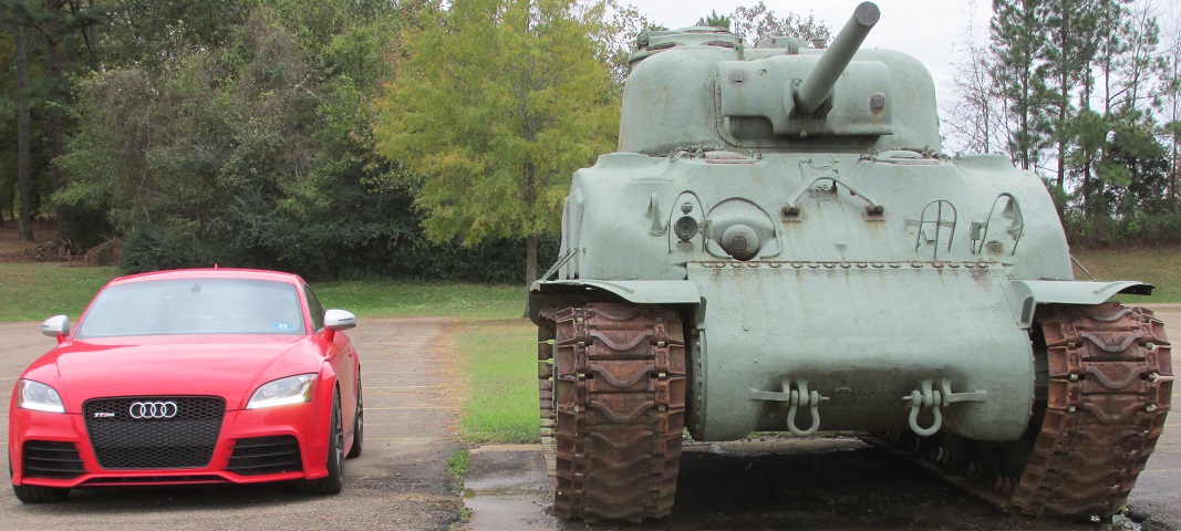
The guard for the siren is next to that for the left headlight cluster, and the ventilators are visible at the top corners of the front hull outboard of the small drivers' hatches. The Audi TT RS parked beside the tank provides some scale.
The effect of adding extended end connectors to both sides of the track are highlighted in this closer view.
The spacer between the hull and suspension bogie is shown here. The four holes in the front of the suspension bracket are for attaching the return roller; the brackets themselves could be used on either side of the tank.
The drive sprockets and idlers also had to be pushed out to make room for the inner end connectors.
Sharing an engine with the M4A1, the exhaust setup was quite similar. The auxiliary engine exhaust can be seen on the left, and one of the air cleaners is on the right.
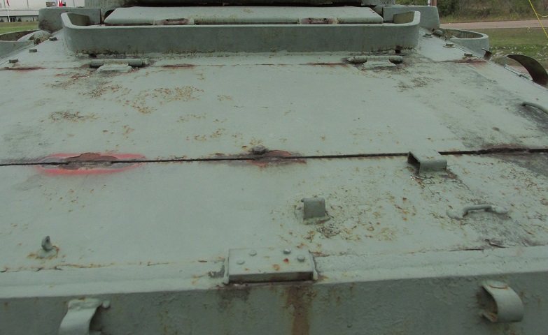
The rear engine compartment top plate was hinged towards the front of the tank, and the air inlet cover and its protective splash guard are directly behind the turret. Fuel filler covers are outboard of the engine air intake.
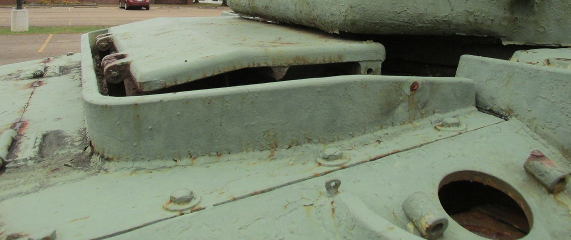
A closer look at the air intake is provided in this image. Both it and the turret ring were provided with splash guards. The cover for the fuel filler cap is missing in the lower right of the picture, revealing the armor thickness. A ventilator housing can be seen inside the turret ring splash guard on the right side of the picture.
The hull applique armor on the assistant driver's side was cut and welded to better conform to the cast front hull.
This composite cast/welded hull lacks applique armor, and the vane sight and spotlight attachment are visible on top of the turret. (Picture from ORD 9 SNL G-104, Vol. 6, 11, and 14.)
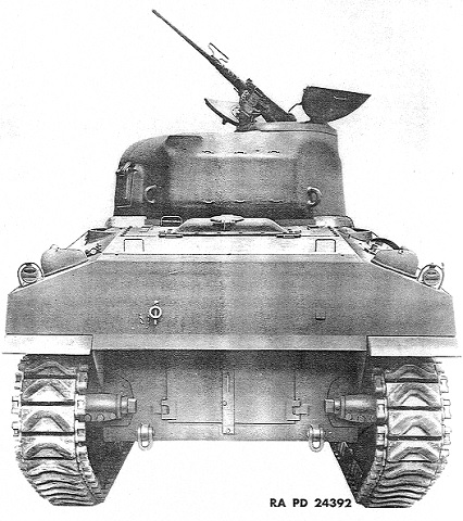
This rear view shows the engine access doors in the lower hull rear and the general shape of the upper rear armor. Compared to the cast M4A1 above, the rear plate is angled instead of curved. (Picture from ORD 9 SNL G-104, Vol. 6, 11, and 14.)
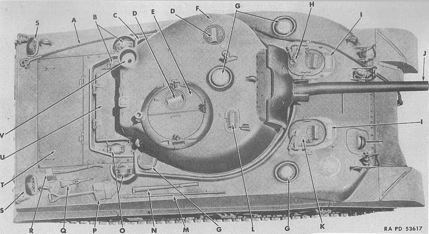
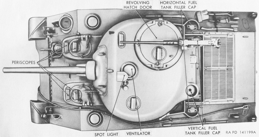
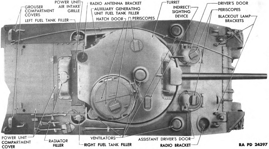
The tank is seen from above here; note that this tank does not have direct vision slots, despite the confusing nomenclature list that follows. A. Towing cable. B. Left fuel tank filler cap covers. C. Auxiliary generator fuel tank filler cap cover. D. Periscope. E. Turret hatch doors. F. Turret. G. Ventilator. H. Driver's door. I. Direct vision door. J. 75-mm. gun. K. Assistant driver's door. L. Indirect sighting device. M. Crowbar. N. Mattock handle. O. Right fuel tank filler cap covers. P. Shovel. Q. Mattock. R. Axe. S. Fuel tank compartment air inlet cover. T. Engine compartment cover, rear. U. Engine compartment air inlet grille cover. V. Radio antenna bracket. (Picture from TM 9-731A Medium Tanks M4 and M4A1.)
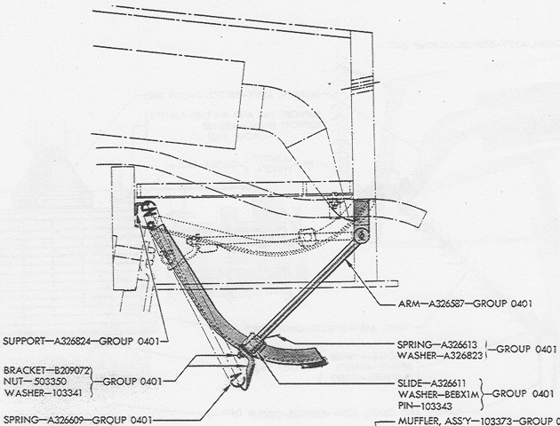
A cross-section of the early exhaust deflector fitted to radial-engined tanks is sketched on the left. The exhaust gases blew down onto the curved metal and then outward and upward, and this reduced the large dust signature that was otherwise raised. The deflector was hinged and could be swung upwards under the hull rear plate, as shown in the ghosted image. The exhaust pipe for the auxiliary generator engine is depicted by the flexible hose snaking under the hull rear plate. The second type of exhaust deflector found on radial-engined tanks is seen on the right. It was also hinged, and could be raised and attached to the outside of the hull rear plate, as shown in the dotted image on the left. The right-hand sketch shows how the air cleaners were still visible on each side of the deflector. The auxiliary generator exhaust pipe is shown between the air cleaner and main engine exhaust pipe. (Picture from ORD 9 SNL G-104, Vol. 6, 11, and 14.)
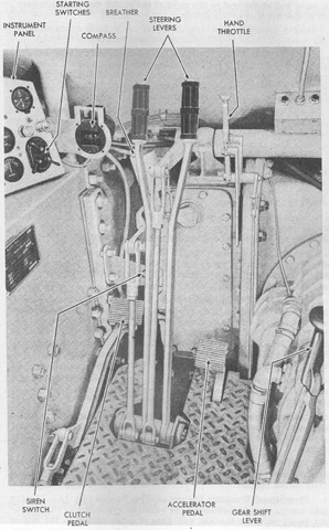
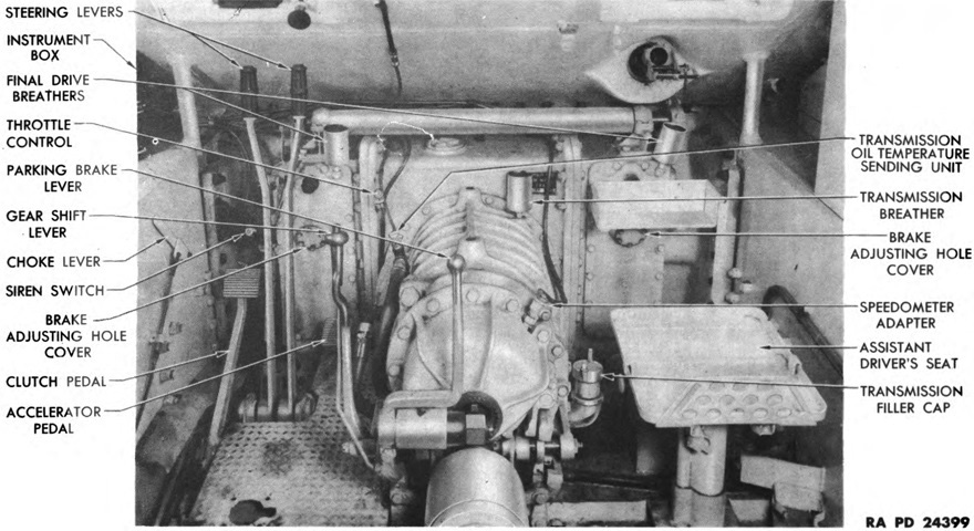
The driver's position of an early-production tank is shown here. (Picture from TM 9-731A Medium Tanks M4 and M4A1.)
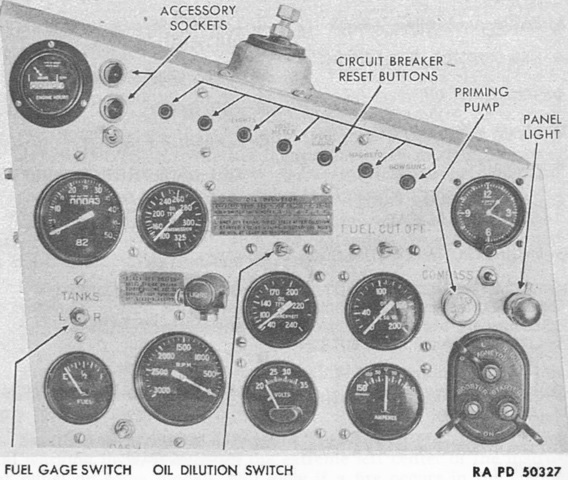
The instrument panel in early machines is seen in this image. (Picture from TM 9-731A Medium Tanks M4 and M4A1.)
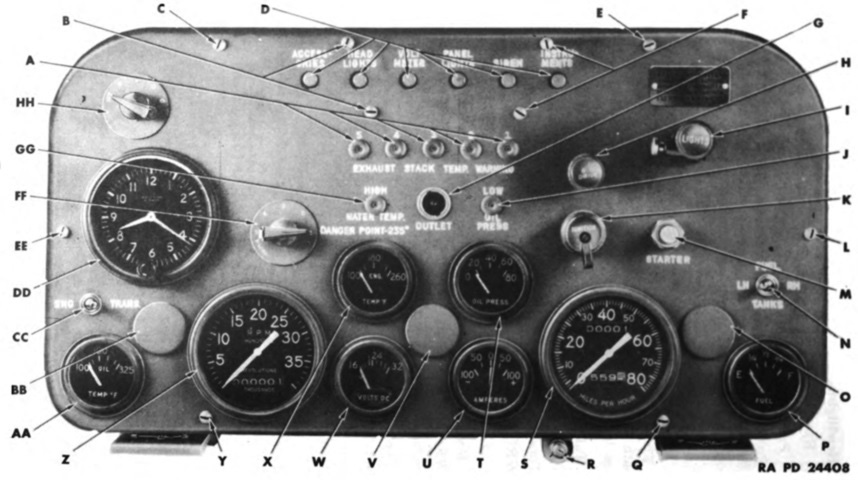
The late-production instrument panel is detailed here. A. Panel attaching screws. B. Fire detector test switch. C. Outlet socket. D. Panel light switch. E. Ammeter. F. Circuit breaker panel attaching screws. G. Engine oil temperature gage. H. Circuit breaker reset button (fuel cut-off). I. Circuit breaker reset button (lights). J. Circuit breaker reset button (accessories). K. Circuit breaker reset button (siren). L. Circuit breaker reset button (instruments). M. Panel light cover. N. Fuel gage. O. Main light switch. P. Fuel gage selector switch. Q. Cranking motor and magneto switch. R. Speedometer. S. Oil pressure gage. T. Fuel cut-off switch. U. Tachometer. V. Low oil pressure warning light. W. Fire signal light (not on later models). (Picture from TM 9-731A Medium Tanks M4 and M4A1.)
Details of an early turret are shown here. This turret lacks the loader's hatch. (Picture from TM 9-1750K Ordnance Maintenance--Tracks and Suspension, Turret and Hull for Medium Tank M4 and Modifications.)
The Westinghouse electric turret traverse system is shown here. When activated, the turret rotated proportionally to the speed with which the traverse handwheel was turned. This was accomplished via grounding the resistors in the silverstat control; the faster the wheel was turned, the more resistors were grounded, and the faster the turret turned. The gunner and commander were each provided with a high-speed switch that interrupted the circuit to the silverstat control and therefore sent full power to the drive motor and enabled the turret to complete a rotation in 15 seconds. This could be used to quickly change targets. Pushing the switch to the right traversed the turret in that direction, and vice-versa. The gunner's switch was on top of his control box, and the commander's was on the turret roof to the left front of his hatch. The commander's switch also interrupted the circuit to the gunner's switch, allowing the commander's switch to take precedence. (Picture from TM 9-731A Medium Tanks M4 and M4A1.)
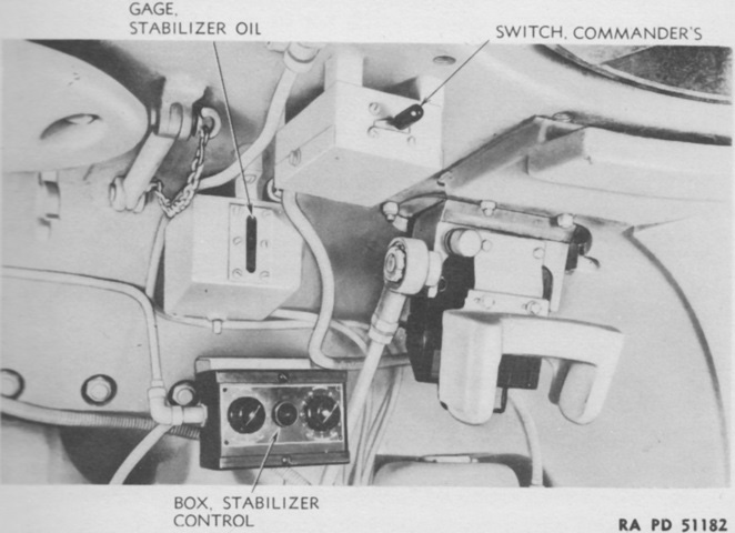
The location of the commander's switch of the electric traverse system is shown here. (Picture from TM 9-1731E Ordnance Maintenance--Electric Traversing Mechanism for Medium Tanks M4 and Modifications.)
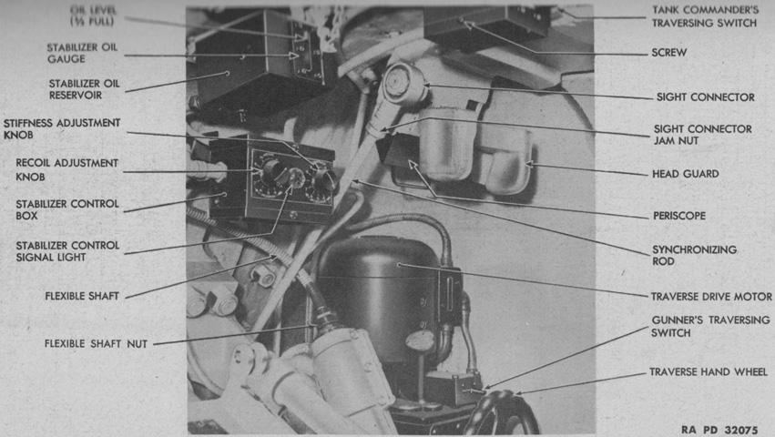
Another overall view of the electric traverse system is provided. (Picture from TM 9-1307 Ordnance Maintenance--75-mm Tank Guns M2 and M3 and Mounts M1, M34, and M34A1.)
There were two versions of the electrical traverse system. Style number 1231700 used a detachable hub to mount the handwheel to the gearbox. This hub was fitted over a long worm shaft. The commander's switch had six contacts, and the silverstat control had two leads. The gear ratio between the handwheel and turret ring in power operation was 72:1. The later style number 1234375 saw the handwheel attached to the gearbox by the hub gear stud, which allowed a shorter worm gear to be used. The hub gear had the number of teeth reduced to 26 from 36, changing the gear ratio in power mode to 100:1. The commander's switch had four contacts, and the silverstat control had three leads. (Picture from TM 9-1731E Ordnance Maintenance--Electric Traversing Mechanism for Medium Tanks M4 and Modifications.)
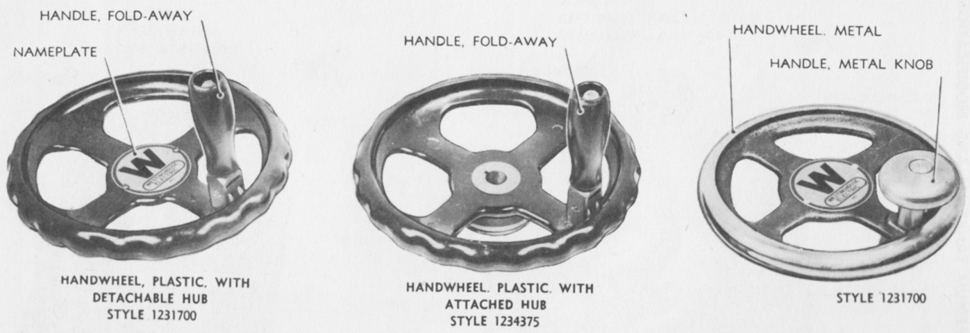
The different handwheels used with the Westinghouse system are shown here. The initial type is on the right; this was of all metal construction with a metal handle, and attached to the hub with four screws. The handwheel on the left was the second type designed, and was plastic with a plastic fold-away handle. Traverse style 1234375 necessitated a new handwheel design, shown in the center. Its hub was not detachable, and it mounted on a short shaft instead of being fitted over the worm shaft. Otherwise it was similar to the second type of wheel for style 1231700. (Picture from TM 9-1731E Ordnance Maintenance--Electric Traversing Mechanism for Medium Tanks M4 and Modifications.)
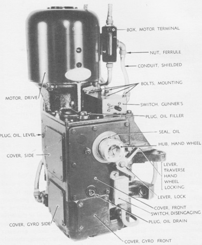
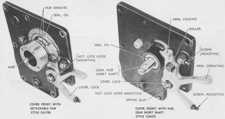
An overview of the gearbox for style 1231700 is presented in this picture. The disengaging switch was normally closed, but held open by the lock lever when the system was in manual traverse mode. (Picture from TM 9-1731E Ordnance Maintenance--Electric Traversing Mechanism for Medium Tanks M4 and Modifications.)
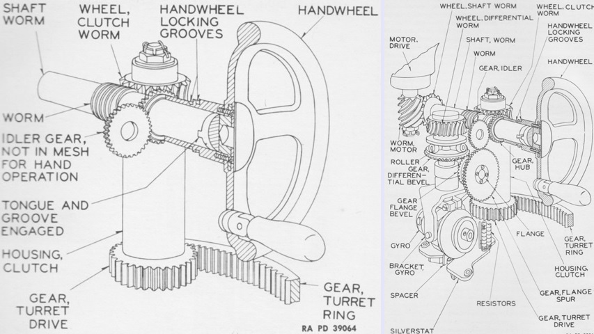
The manual geartrain for the Westinghouse traverse system is diagrammed on the left. To traverse the turret manually, the traverse handwheel locking lever was seated into the groove by the handwheel. The handwheel tongue then directly engaged the worm shaft groove. The worm shaft engaged the clutch worm wheel, which connected to the turret drive gear via the clutch housing. The handwheel had a 464:1 ratio in manual mode.
The powered geartrain for the Westinghouse traverse system is drawn on the right. To traverse the turret electrically, the locking arm of the lock lever was seated into the groove by the gearbox, pulling the handwheel out toward the gunner. The handwheel was connected to the differential bevel gear via the hub, idler, flange spur, and flange bevel gears. The differential bevel gear turned the roller, which pressed against and moved the shaft carrying the gyro. This movement closed leaves on one side of the silverstat control via the spacer on the bottom of the gyro motor, which allowed current to flow through the generator field connected with that side of the circuit. Current was then produced by the generator and sent to the drive motor, which drove the worm shaft, which transmitted this movement to the clutch worm wheel, which turned the turret drive and traversed the turret. Faster movement of the handwheel closed more leaves on the silverstat control, resulting in more produced current and faster turret traverse. The gyro was used to anticipate movement of the handwheel and therefore smooth turret movement. (Picture from TM 9-1731E Ordnance Maintenance--Electric Traversing Mechanism for Medium Tanks M4 and Modifications.)
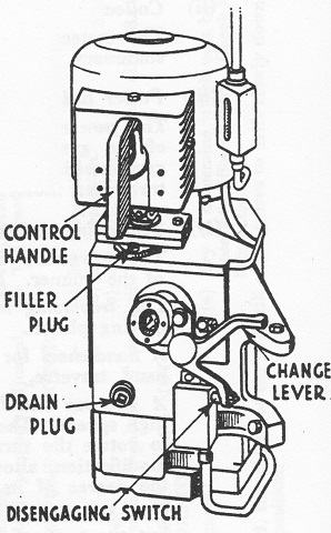
The high-speed switch in the Westinghouse traverse system was later replaced with a high-speed control handle that allowed variation in the fast turret traverse up to the maximum speed. The traverse handwheel is omitted on this drawing for clarity, but its mounting socket is seen next to the change lever. (Picture from Sherman Tanks 75 mm. M3 Gun and Coaxial .30" Browning Machine Gun Armament Training Pamphlet.)
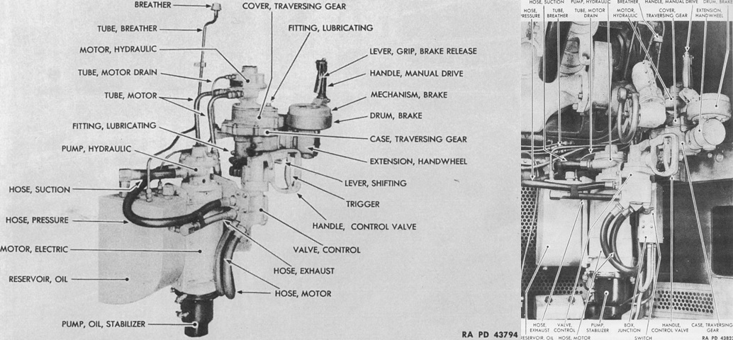
The Logansport hydraulic traversing mechanism is shown isolated on the left and installed in the turret on the right. Powered traverse was provided when the electrical motor was turned on and the shifting lever was in the up position. The gunner could then squeeze the trigger on the control valve handle and twist it in the desired direction of traverse; higher amplitude of twist resulted in faster traverse. Pushing the shifting lever down enabled the manual drive handle for manual traverse. The switch on the junction box turned on the electric motor to energize the system. The capacity of the oil reservoir was ~3.5gal (~13L). (Picture from TM 9-1731F Ordnance Maintenance--Hydraulic Traversing Mechanism (Logansport) for Medium Tanks M4 and Modifications.)
The Oilgear hydraulic turret traverse mechanism functioned in a broadly similar manner as the Logansport, but was less sensitive to variances in friction, smoother in action, and more sensitive to inputs. With the electric drive motor turned on and the shift lever in the up position, the control pump handle was twisted to traverse the turret in the desired direction. A larger amount of twist led to faster traverse. Manual traverse was made available by pushing the shift lever to the down position. The oil reservoir had a capacity of 1gal (3.8L). (Picture from TM 9-1731G Ordnance Maintenance--Hydraulic Traversing Mechanism (Oilgear) for Medium Tanks M4 and Modifications.)
The lens-erecting telescope M55 introduced with the gun mount M34A1 was a 3x device with a 12°19' field of view. Its reticle was identical to that of the telescope M38 found in the periscope M4. (Picture from TM 9-731A Medium Tanks M4 and M4A1.)
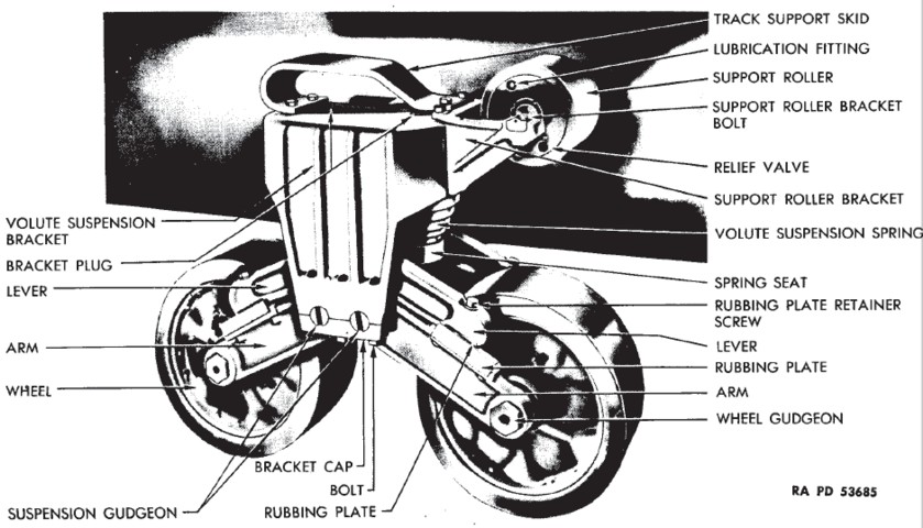
Parts of the suspension bogie are labeled in this image. (Picture from TM 9-1750K Ordnance Maintenance--Tracks and Suspension, Turret and Hull for Medium Tank M4 and Modifications.)
Compared to other Shermans, the bogies on the M4A4 were spaced farther apart to compensate for the extended hull necessitated by the large A57 engine. This tank is fitted with the early gun mount M34 without armor protection for the coaxial MG. (Picture from Part II, SNL G-104, Vol. IX.)
Though showing considerable signs of abuse, the larger space between the suspension bogies is shown here to good effect.
The need for the bulges in the engine compartment deck and floor can be seen in this sectional view; the engine's fan and radiators would not have otherwise fit. Note that the hull has not been lengthened to scale in this image. The difference can be contrasted with the picture above. (Picture from Part II, SNL G-104, Vol. IX.)
Distinctive features of the rear of the M4A4 Sherman can be seen here. Immediately apparent is the radiator bulge in the deck. The M4A4 was built with two engine access doors in the rear hull. The radio bustle is apparent in the turret rear, along with antenna mounts in the roof of the turret, and a pistol port is visible on the turret's left side. (Picture from Part II, SNL G-104, Vol. IX.)
Details of the top of the tank, including tool stowage, is shown here. Note the gun mount M34. (Picture from TM 9-754 Medium Tank M4A4.)

The engine radiator filler cover and the power unit air intake grille are isolated in this image. The foundry mark on the turret bustle indicates it was cast at Continental Foundry and Machine Company's Wheeling, West Virginia, plant.

The underside of the rear hull featured three large engine access panels. The hull floor blister that provided clearance for the power unit's fan is visible ahead of the center access panel, and the floor escape hatch opening can be seen toward the front right corner of the tank. Note that this machine is fitted with a nonstandard experimental horizontal volute spring suspension.

The hull floor blister for the power unit cooling fan was a separate piece securely bolted to the hull.
Ammunition stowage is detailed in this sketch. (Picture from TM 9-754 Medium Tank M4A4.)
This top-down view of the Westinghouse turret traverse system illustrates why it was necessary to add applique armor outside the gunner's position. A section of the inside turret wall was ground away to make room for the controls for all three traverse systems. (Picture from Part II, SNL G-104, Vol. IX.)
The drivers' positions are shown here. (Picture from TM 9-754 Medium Tank M4A4.)
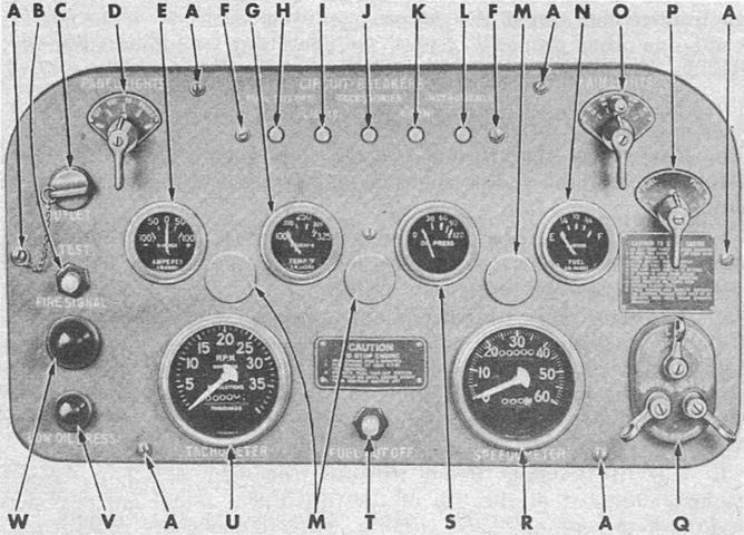
The driver's instrument panel is labeled in this image. A. Exhaust stack temperature warning indicators. B. Circuit breaker mounting plate retaining screws. C. Cover attaching screw. D. Circuit breaker reset buttons. E. Cover attaching screw. F. Circuit breaker mounting plate retaining screws. G. Instrument box outlet socket. H. Black-out driving light switch. I. Light switch. J. Low oil pressure warning indicator. K. Ignition switch. L. Cover attaching screw. M. Starter switch. N. Fuel gage selector switch. O. Instrument box light cover. P. Fuel gage. Q. Cover attaching screw. R. Speedometer reset knob. S. Speedometer. T. Oil pressure gage. U. Ammeter. V. Instrument box light cover. W. Voltmeter. X. Water temperature gage. Y. Cover attaching screw. Z. Tachometer. AA. Power unit and transmission oil temperature gage. BB. Instrument box light cover. CC. Power unit and transmission oil temperature gage selector switch. DD. Clock. EE. Cover attaching screw. FF. Water temperature gage selector switch. GG. High water temperature warning indicator. HH. Instrument box light switch. (Picture from TM 9-754 Medium Tank M4A4.)
The glass plate on the inside of the direct vision slit that protected the crew from fragments or splash is in place on this tank. (Picture from TM 9-754 Medium Tank M4A4.)
The turret has been removed, providing a view of the hull interior. The battery box is open, and a 75mm ammunition rack is visible in the hull sponson in the upper right corner of the image. (Picture from TM 9-754 Medium Tank M4A4.)
The rear of the fighting compartment is shown with the turret removed. (Picture from TM 9-754 Medium Tank M4A4.)
In addition to all A57s manufactured for the medium tank M3A4, power units with serial numbers M4A4-1001 through M4A4-2304 inclusive had a water pump for each engine. These units had the generator mounted on engine 2 and driven by that engine's water pump belt. The fuel pump was found on the distributor end of the crankcase and was driven by the accessory shaft. M4A4s with serial numbers 4805-5803 were constructed with these A57s. Power units with serial numbers M4A4-1001 through M4A4-3211 inclusive had thermostats in the cooling system mounted in each engine's water outlet adapter. These units were used in M4A4s serial numbers 4805-6204 and 16555-17112. Subsequent engines had a bypass-type thermostat mounted in the cylinder head adapter of engine 1 and the radiator inlet adapter of engines 2-5. A57s serial numbers M4A4-1001 to M4A4-4412 inclusive were built with a fully-enclosed clutch; a ventilated clutch was used thereafter. A57s with early clutches were used in M4A4s serial numbers 4805-6204 and 16555-17793.
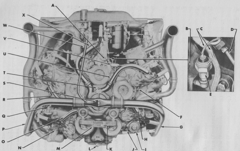
This image is of the distributor end of an A57 with multiple water pumps. A. Cleaner, air, crankcase ventilator, assembly. B. Pump, water, assembly (no. 1 engine). C. Plate, engine lifter and step, assembly. D. Filter, oil, with clamp, assembly. E. Tube, water pump air relief (engine no. 1 to no. 5). F. Coil, ignition, assembly (no. 5 engine). G. Pipe, exhaust (nos. 4 and 5 engines). H. Tube, fuel pump to branch connection, assembly (for nos. 4 and 5 carburetors). I. Connection, water pump air relief. J. Tube, fuel pump to no. 1 carburetor, assembly. K. Pump, water, assembly (no. 5 engine). L. Distributor, ignition, assembly (no. 5 engine). M. Plate, serial number, engine. N. Coil, ignition, assembly (no. 3 engine). O. Tube, fuel pump to branch connection, assembly (for nos. 2 and 3 carburetors). P. Tube, water pump air relief (engine no. 4 to no. 5). Q. Tube, radiator outlet, assembly (nos. 4 and 5 engines). R. Coil, ignition, assembly (no. 4 engine). S. Pump, water, assembly (no. 4 engine). T. Distributor, ignition, assembly (no. 4 engine). U. Pump, fuel, assembly. V. Support, engine, rear. W. Pan, oil, assembly. X. Plug, drain, oil pan. Y. Distributor, ignition, assembly (no. 3 engine). Z. Pump, water, assembly (no. 3 engine). AA. Tube, radiator outlet, assembly (nos. 2 and 3 engines). BB. Cock, drain, cylinder water jacket, assembly. CC. Distributor, ignition, assembly (no. 2 engine). DD. Distributor, ignition, assembly (no. 1 engine). EE. Tube, water pump air relief (engine no. 2 to no. 3). FF. Pump, water, assembly (no. 2 engine). GG. Connection, radiator outlet tube, assembly (no. 1 engine). HH. Gear, reduction, tachometer drive, assembly. II. Generator, assembly. JJ. Coil, ignition, assembly (no. 1 engine). KK. Pipe, exhaust (nos. 1, 2, and 3 engines). LL. Tube, water pump air relief (engine no. 1 to no. 2). (Picture from TM 9-1750F Ordnance Maintenance--Power Unit for Medium Tanks M3A4 and M4A4.)
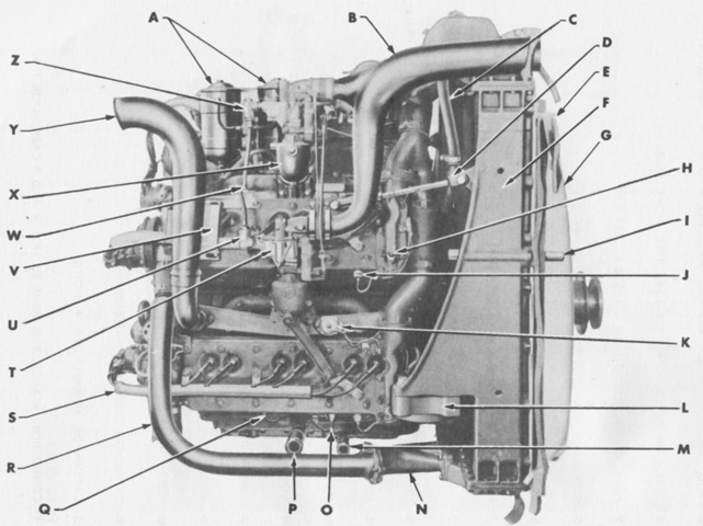
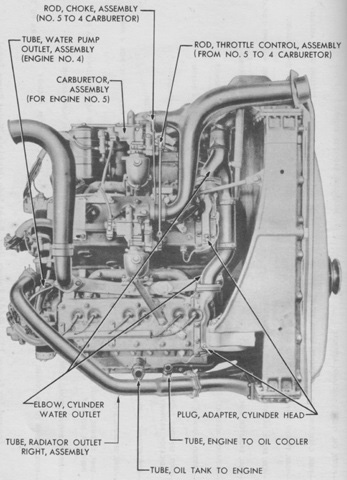
The right side of a multiple water pump unit is labeled here. A. Filter, oil, engine, w/clamp, assembly. B. Tube, carburetor to air cleaner, upper, right, assembly. C. Hose, engine crankcase vent air cleaner outlet pipe. D. Rod, brace, radiator to engine, right, assembly. E. Seal, radiator, side, right, assembly. F. Radiator, assembly. G. Shroud, radiator, assembly. H. Unit, sending, engine water temperature warning indicator, assembly. I. Pipe, exhaust, auxiliary generator unit. J. Unit, sending, engine water temperature gage, assembly. K. Unit, sending, exhaust stack temperature warning indicator, assembly. L. Support, engine, front, right. M. Hose, engine to oil cooler, engine end, assembly. N. Outlet, radiator, right. O. Unit, sending, engine oil pressure gage, assembly. P. Hose, oil tank to engine, engine end, assembly. Q. Unit, sending, engine oil pressure warning indicator. R. Tube, outlet, radiator, right, assembly. S. Cable, spark plug, w/tube, assembly. T. Carburetor, assembly (no. 4 engine). U. Filter, fuel, carburetor, assembly. V. Shield, ignition cable tube. W. Connection, branch, fuel pump to nos. 4 and 5 carburetor tube. X. Elbow, engine intake manifold (engine no. 5). Y. Pipe, exhaust, upper, right, assembly. Z. Filter, fuel, carburetor, assembly. (Picture from TM 9-1750F Ordnance Maintenance--Power Unit for Medium Tanks M3A4 and M4A4.)
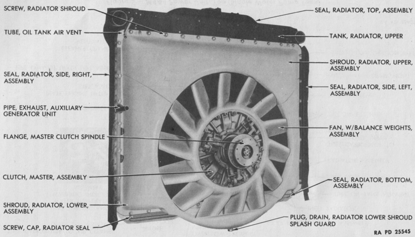
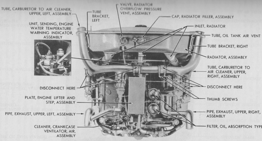
When looking at the fan end of the power unit, it is easy to see why the bulges in the hull deck and floor were necessary. The cooling system used 32gal (120L) of coolant. (Picture from TM 9-1750F Ordnance Maintenance--Power Unit for Medium Tanks M3A4 and M4A4.)
A57s with serial numbers above M4A4-2304 used a single water pump, which simplified maintenance. In tanks with these units, the generator was found in the fighting compartment and driven by the propeller shaft via a belt. The fuel pump was on the distributor end of engine no. 4 and driven by the camshaft.
A. Cock, drain, engine cylinder water jacket, assembly (engine no. 1). B. Block, engine cylinder (engine no. 1). C. Harness, engine wiring, assembly. D. Tube, outlet, oil filter assembly. E. Unit, sending, engine oil pressure warning indicator. F. Cock, drain, engine cylinder water jacket, assembly (engine no. 5). G. Tube, outlet, radiator, right, assembly. H. Tube, outlet, water pump, assembly (engine no. 4). I. Pump, fuel, assembly. J. Cock, drain, engine cylinder water jacket, assembly (engine no. 4). K. Support, engine, rear. L. Plug, drain, oil pan. M. Plate, name, engine serial number. N. Cock, drain, engine cylinder water jacket, assembly (engine no. 3). O. Tube, outlet, water pump, assembly (engine no. 3). P. Tube, outlet, radiator, left, assembly. Q. Cock, drain, engine cylinder water jacket, assembly (engine no. 2). R. Tube, outlet, water pump, assembly (engine no. 2). S. Pump, water, assembly. T. Fitting, grease, water pump body. U. Tube, outlet, water pump, assembly (engine no. 5). V. Connection, main branch, fuel pump to carburetor tube, assembly. W. Tube, overflow, radiator, assembly. X. Tube, outlet, water pump, assembly (engine no. 1). (Picture from TM 9-1750F Ordnance Maintenance--Power Unit for Medium Tanks M3A4 and M4A4.)
The late-production power unit is seen from the left. (Picture from TM 9-1750F Ordnance Maintenance--Power Unit for Medium Tanks M3A4 and M4A4.)
The right side of the late power unit is labeled here. (Picture from TM 9-1750F Ordnance Maintenance--Power Unit for Medium Tanks M3A4 and M4A4.)
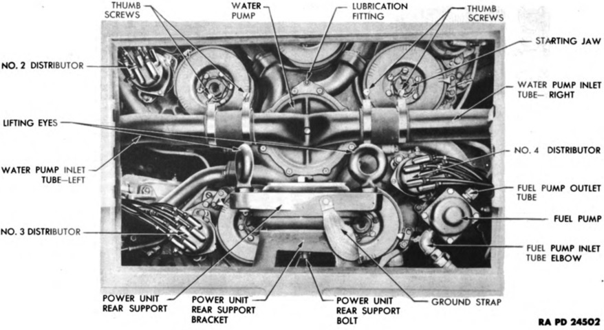
The single water pump power unit is depicted from above. (Picture from TM 9-1750F Ordnance Maintenance--Power Unit for Medium Tanks M3A4 and M4A4.)
The rear hull engine access doors on a single water pump tank are open in this picture. (Picture from TM 9-754 Medium Tank M4A4.)
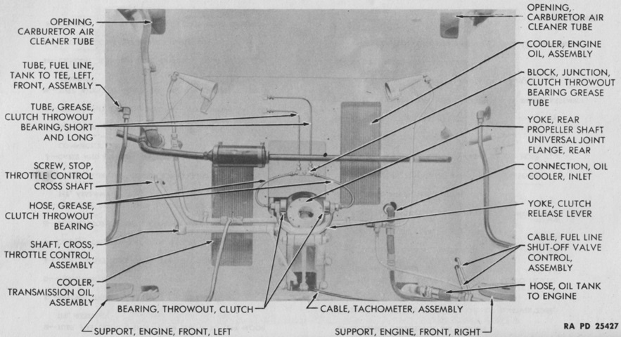
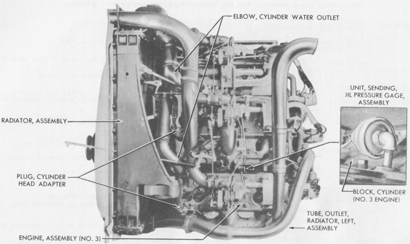
The front of the power unit compartment is labeled here with the engine removed. (Picture from TM 9-1750F Ordnance Maintenance--Power Unit for Medium Tanks M3A4 and M4A4.)
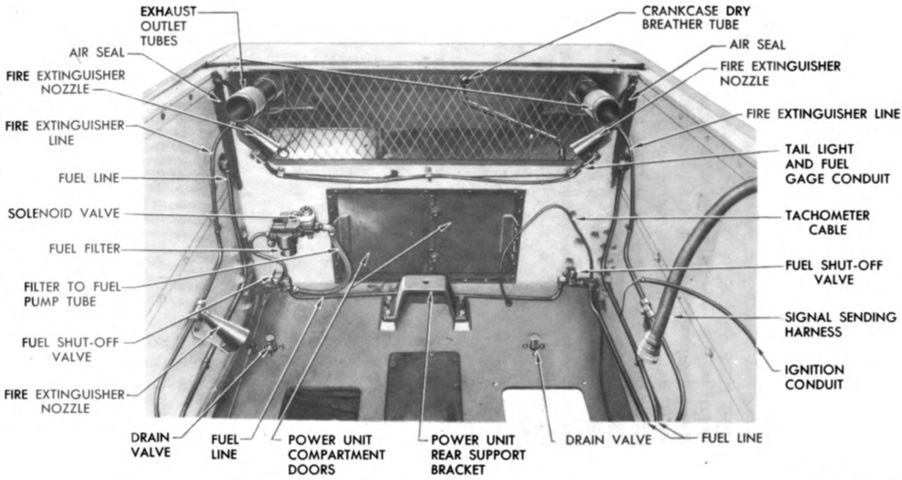
The rear of the power unit compartment is shown in this image. (Picture from TM 9-754 Medium Tank M4A4.)
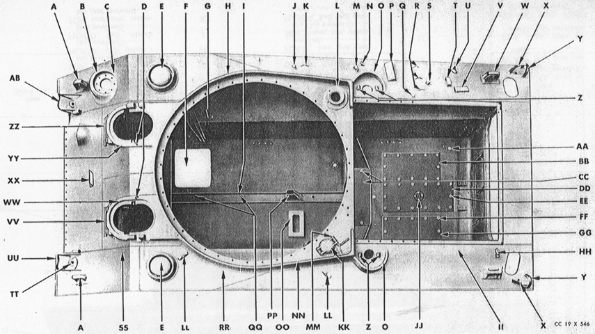
The engine compartment access panels can be better seen in this top-down view of an empty hull. (Picture from Part II, SNL G-104, Vol. IX.)
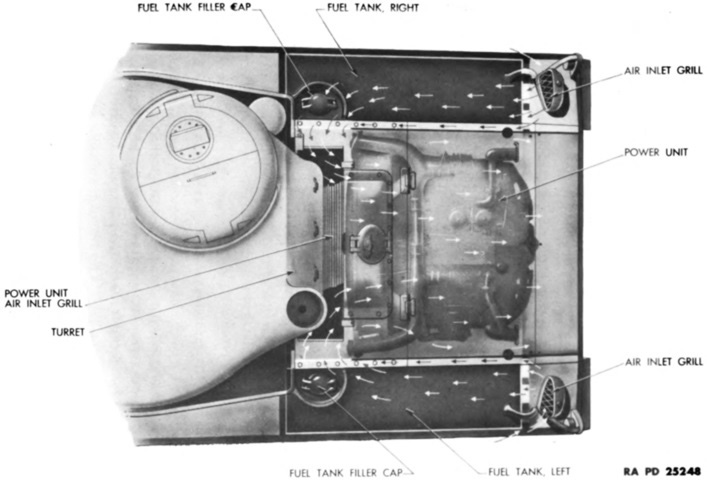
A horizontal 80gal (300L) fuel tank was mounted in each sponson rear. Starting with tank 17794, the fuel tanks were insulated by a covering of metal foil shielding against the heat put out by the A57. Air was circulated through the fuel tank compartments by the power unit fan as depicted here. (Picture from TM 9-754 Medium Tank M4A4.)
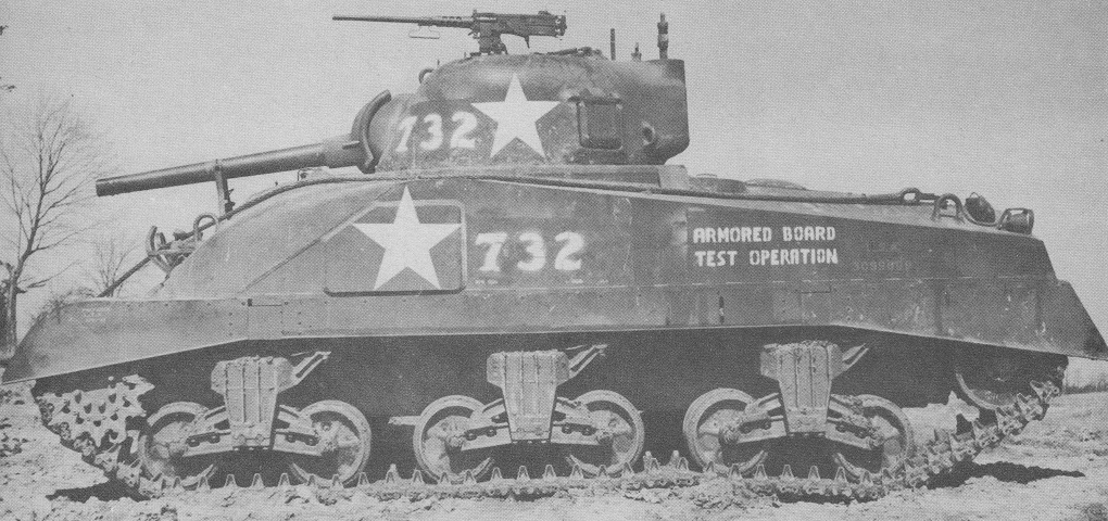
The increased space between the bogies on this M4A6 is similar to that found on the M4A4. The weld line showing where the cast upper front hull was attached to the rest of the hull is apparent as it slopes downward and forward from behind the drivers' hatches, just in front of the applique armor welded over the sponson ammunition rack. The bulge on the rear deck can be seen just behind the guard for the fuel filler cap. The 75mm gun on this tank is secured in the travel lock. (Picture from Development of Armored Vehicles, volume 1: Tanks.)
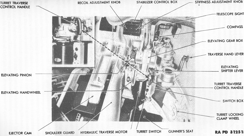
The gunner's controls with the Oilgear hydraulic turret traversing system are shown here. The commander was eventually provided with a master control handle that allowed him to traverse the turret and override the gunner's control if necessary. (Picture from TM 9-756 Medium Tank M4A6.)
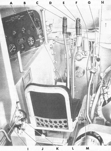
The driver's position is seen in this image. An advantage compared to other radial-engined medium tanks was that oil accumulation in the combustion chambers could be expelled by pressing the engine starting switch with the engine governor control hand lever in the off position, obviating the need to crank the engine over by hand. A. Instrument panel. B. Clutch pedal. C. Steering brake control lever--left D. Steering brake control lever--right. E. Siren switch. F. Transmission gearshift lever. G. Governor control hand lever. H. Hand throttle control. I. Fuel tank selector lever. J. Radio master switch (12-volt). K. Battery master switch (24-volt). L. Parking brake operating pedal. M. Accelerator pedal. (Picture from TM 9-756 Medium Tank M4A6.)
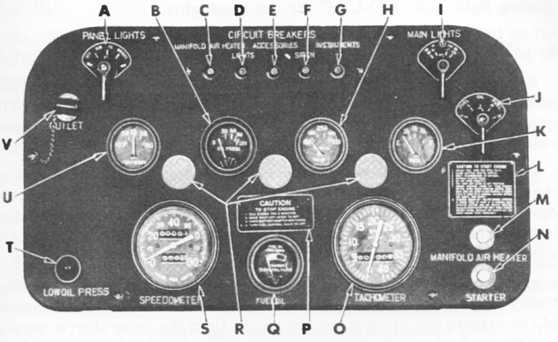
The driver's instrument panel is highlighted. A. Panel light switch. B. Engine oil pressure gage. C. Circuit breaker reset button (manifold air heater). D. Circuit breaker reset button (lights). E. Circuit breaker reset button (accessories). F. Circuit breaker reset button (siren). G. Circuit breaker reset button (instruments). H. Engine oil temperature gage. I. Main light switch. J. Fuel and oil level gage selector switch. K. Fuel and oil level gage. L. Instruction plate (to start engine). M. Manifold air heater switch. N. Starting button. O. Tachometer. P. Instruction plate (to stop engine). Q. Fuel oil pressure gage. R. Instrument panel lights. S. Speedometer. T. Low oil pressure warning light. U. Ammeter. V. Electrical outlet. (Picture from TM 9-756 Medium Tank M4A6.)
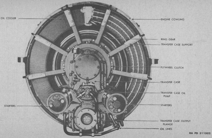
The front of the RD-1820 is seen here. The engine was governed under full load at 2,000rpm; and its cylinders' bore was 6.125" (15.58cm) and stroke was 6.875" (17.46cm), for a displacement of 1,823in³ (29,870cm³). It had a 15.5:1 compression ratio; weighed 3,900lb (1,800kg) without its air cleaners, fuel filter, and oil filter; was 55" (140cm) in diameter; and was 70.16" (178.2cm) long with its starters and air inlet elbows. (Picture from TM 9-1756A Ordnance Maintenance--Ordnance Engine Model RD-1820 (Caterpillar).)
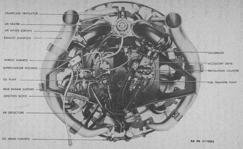
Details of the rear of the engine are shown in this image. Firing order was 1-3-5-7-9-2-4-6-8, and low idle speed was 650rpm. (Picture from TM 9-1756A Ordnance Maintenance--Ordnance Engine Model RD-1820 (Caterpillar).)
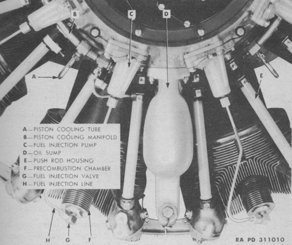
A close-up of the front of the engine with the front support removed reveals the system used to cool the aluminum pistons, which sprayed jets of oil on their undersides. (Picture from TM 9-1756A Ordnance Maintenance--Ordnance Engine Model RD-1820 (Caterpillar).)
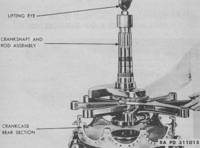
The crankshaft and connecting rods are being removed from the disassembled crankcase. The crankshaft had one crankpin that carried the master connecting rod, and eight articulated rods connected to a circular web on the master rod by knuckle pins. (Picture from TM 9-1756A Ordnance Maintenance--Ordnance Engine Model RD-1820 (Caterpillar).)
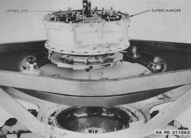
The supercharger is being lifted from the rear of the engine. The finned diffuser plate is visible underneath the supercharger. (Picture from TM 9-1756A Ordnance Maintenance--Ordnance Engine Model RD-1820 (Caterpillar).)
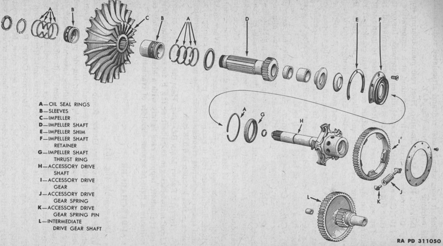
An exploded view of the 10:1 ratio supercharger is provided here. (Picture from TM 9-1756A Ordnance Maintenance--Ordnance Engine Model RD-1820 (Caterpillar).)
The RD-1820 used a transfer case that lowered the line of drive from the center of the engine, allowing the propeller shaft to be mounted lower than with radial engines lacking this feature. The transfer case increased the propeller shaft speed by 1.5 times the crankshaft speed. (Picture from TM 9-1756A Ordnance Maintenance--Ordnance Engine Model RD-1820 (Caterpillar).)
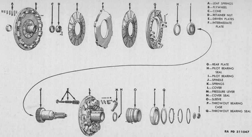
The clutch assembly consisted of a cover assembly with pressure plate, a driving disk that engaged the flywheel, and two driven disks that slid on the splined hub of the clutch shaft. (Picture from TM 9-1756A Ordnance Maintenance--Ordnance Engine Model RD-1820 (Caterpillar).)
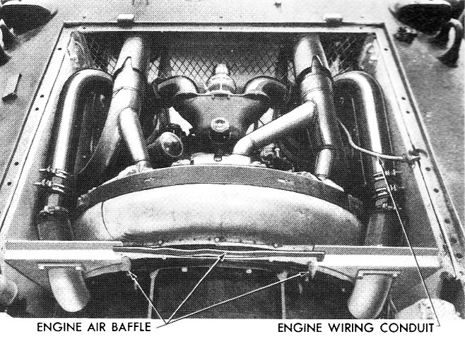
The engine is seen here installed in the hull. (Picture from TM 9-756 Medium Tank M4A6.)
The transmission and final drive assembly is shown here removed from the vehicle. Note the lack of parking brake lever compared to the assembly above; on later vehicles the parking brake function was given instead to the steering levers. (Picture from TM 9-756 Medium Tank M4A6.)
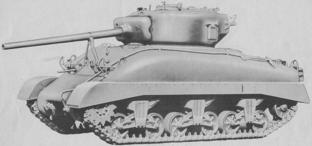
When comparing 76mm gun tanks with the 75mm gun tanks, the new turret borrowed from the medium tank T23 is an obvious difference. A new gun travel lock was also needed for the longer weapon, and it is deployed. The stowage brackets for the .50cal machine gun can be glimpsed on the turret bustle. (Picture from TM 9-731AA Medium Tank M4 (105-mm Howitzer) and Medium Tank M4A1 (76-mm Gun).)
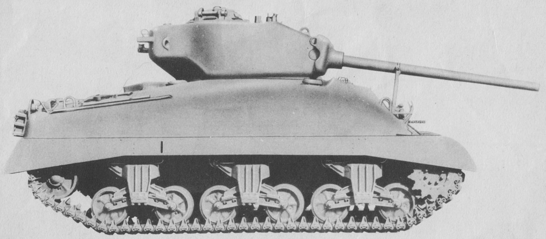
The new turret can be seen here in profile. The much longer gun tube is obvious compared to the 75mm gun M3. (Picture from TM 9-731AA Medium Tank M4 (105-mm Howitzer) and Medium Tank M4A1 (76-mm Gun).)
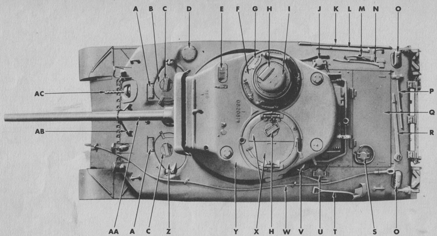
The top of a tank with a commander's vision cupola and loader's split hatch is diagrammed here. A. Periscope holder. B. Assistant driver's hatch door. C. Periscope. D. Ventilator. E. Sighting device. F. Commander's vision cupola. G. Direct vision block. H. Periscope. I. Cupola escape door. J. Right fuel tank filler cap cover. K. Crow bar. L. Mattock handle. M. Mattock. N. Ax. O. Grouser compartment scoop. P. Sledge hammer. Q. Engine compartment cover, rear. R. Track adjusting wrench. S. Engine oil tank filler cap cover. T. Shovel. U. Left fuel tank filler cap cover. V. Auxiliary generator fuel tank filler cap cover. W. Towing cable. X. Turret hatch doors. Y. Turret. Z. Driver's hatch door. AA. 76-mm gun. AB. Gun traveling lock. AC. .30 cal. gun. (Picture from TM 9-731AA Medium Tank M4 (105-mm Howitzer) and Medium Tank M4A1 (76-mm Gun).)
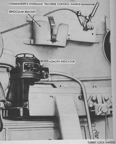
The tank commander's hydraulic traverse control handle for the Oilgear traverse system would override inputs by the gunner, allowing the commander to take control of the turret at any time. A button was pressed on top, then the handle was pushed forward to traverse counterclockwise or pulled backwards to traverse clockwise. (Picture from TM 9-731AA Medium Tank M4 (105-mm Howitzer) and Medium Tank M4A1 (76-mm Gun).)
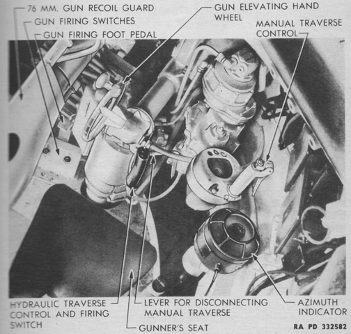
The gunner's controls are labeled in this image. (Picture from TM 9-731AA Medium Tank M4 (105-mm Howitzer) and Medium Tank M4A1 (76-mm Gun).)
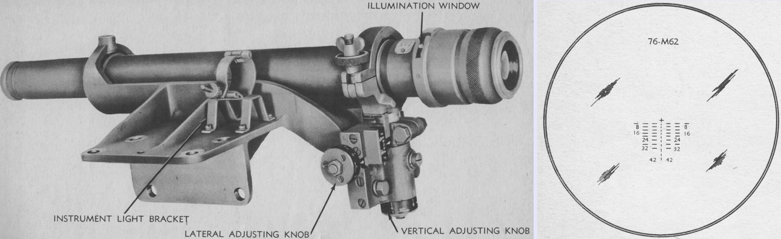
The telescope M71D is seen here installed in the telescope mount M57, which would be attached to the right side of the gun mount. The M71D was a straight, lens-erecting 5x telescope with a 13° field of view. The instrument light M33 could be secured in the bracket on the telescope mount when an illuminated reticle was necessary. The reticle for the telescope is drawn on the right. It was graduated for the armor-piercing capped projectile M62 fired with a 2,600feet/sec (790m/s) muzzle velocity and a 1.0 mil jump. The cross at the top of the reticle was used when boresighting, and the range markings below were in hundreds of yards. Each horizontal line and space represented a 5-mil deflection. (Picture from TM 9-731AA Medium Tank M4 (105-mm Howitzer) and Medium Tank M4A1 (76-mm Gun).)
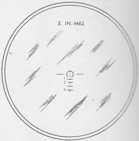
The reticle of the telescope M47 in the periscope M4 is the subject of this sketch. (Picture from TM 9-731AA Medium Tank M4 (105-mm Howitzer) and Medium Tank M4A1 (76-mm Gun).)
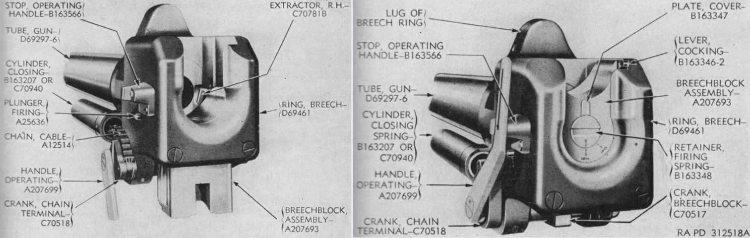
The sliding wedge breechblock of the 76mm gun is shown open on the left and closed on the right. The gun weighed 1,206lb (574.0kg) without the muzzle brake. There were 28 grooves in the bore, which were .040" (.102cm) deep and .1866" (.4740cm) wide, with the lands being .150" (.38cm) wide. (Picture from TM 9-1308 Ordnance Maintenance--76-mm Guns M1A1C and M1A2; Gun Mount M1 and Combination Gun Mount M62 for Combat Vehicles.)
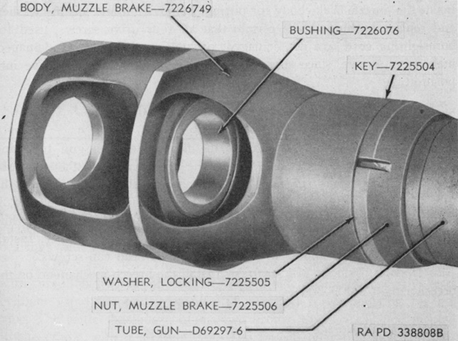
The muzzle brake M2 is seen installed on the ordnance. (Picture from TM 9-1308 Ordnance Maintenance--76-mm Guns M1A1C and M1A2; Gun Mount M1 and Combination Gun Mount M62 for Combat Vehicles.)
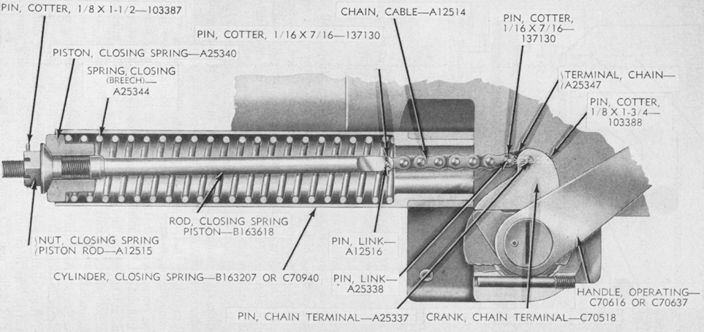
A cross-section of the 76mm gun's closing spring is drawn here. This spring worked to close the breech when a round was inserted. (Picture from TM 9-1308 Ordnance Maintenance--76-mm Guns M1A1C and M1A2; Gun Mount M1 and Combination Gun Mount M62 for Combat Vehicles.)
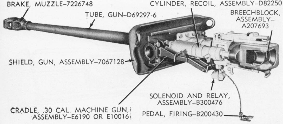
The 76mm gun M1A2 is installed in the combination gun mount M62, but the coaxial machine gun and recoil guard are not present. Note that the breechblock is horizontal, and closed toward the loader. (Picture from TM 9-1308 Ordnance Maintenance--76-mm Guns M1A1C and M1A2; Gun Mount M1 and Combination Gun Mount M62 for Combat Vehicles.)
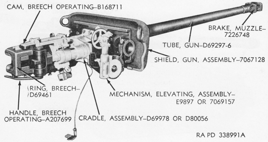
The combination gun mount M62 is seen from the opposite side. (Picture from TM 9-1308 Ordnance Maintenance--76-mm Guns M1A1C and M1A2; Gun Mount M1 and Combination Gun Mount M62 for Combat Vehicles.)
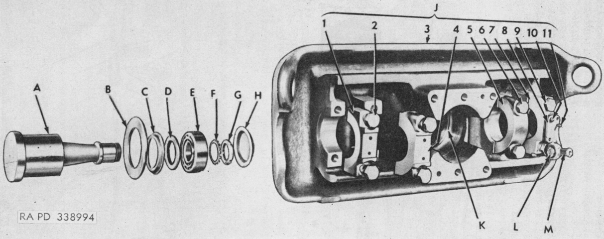
The combination gun mount M62's gun shield assembly is shown partially disassembled. A. Trunnion, gun mount. B. Spacer (trunnion). C. Retainer, oil seal. D. Seal, oil, type ML, 5.00 x 6.258 x ⅝. E. Bearing, roller. F. Washer, lock, ball bearing. G. Nut, lock, ball bearing. H. Cap, bearing closure. J. Shield, gun, assembly. 1. Cap, trunnion, left outside. 2. Screw (trunnion cap); washer, lock, 1⅛" (2.858cm). 3. Shield, gun. 4. Cap, trunnion, left inside. 5. Cap, trunnion, right inside. 6. Screw (trunnion cap); washer, lock, 1⅛" (2.858cm). 7. Cap, trunnion, right outside; pin, 0.375 x 1¼. 8. Anchor, periscope linkage. 9. Screw (trunnion cap); washer, lock, 1⅛" (2.858cm). 10. Bolt, hex-hd., ½-20NF-2 x 1⅛; washer, lock, ½" (1.3cm). 11. Pin, 0.375 x 1. K. Seal, oil, type MW, 6 29/64 x 7.256 x ¼. L. Stud, bearing; nut, lock, ball bearing; bearing, ball; washer, lock, ball bearing. M. Connector, periscope linkage; ring (connector bearing). (Picture from TM 9-1308 Ordnance Maintenance--76-mm Guns M1A1C and M1A2; Gun Mount M1 and Combination Gun Mount M62 for Combat Vehicles.)
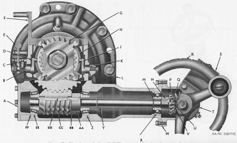
The gun mount M62 could be found with either of two elevation mechanisms. A cross-section of elevating mechanism 7069157 is drawn here; it used shims for adjustment of the cone worm. A. Retainer, bearing. B. Shim (shifter). C. Spring (stabilizer switch arm). D. Shifter, gear left. E. Arm, stabilizer switch. F. Cover, shifter. G. Gear, spring. H. Gear, internal. J. Shifter, gear right. K. Shim (shifter). L. Box, elevating gear. M. Washer (worm gear shaft). N. Key, Woodruff, 5/32 x ⅝. P. Pinion, worm shaft. Q. Shaft, handwheel gear. R. Handwheel assembly. S. Index, handwheel, assembly. T. Housing, handwheel gear. U. Nut, safety, ⅜-24NF-3. V. Washer (worm gear shaft). W. Shim (box to housing). X. Bearing, ball. Y. Shaft, worm gear. Z. Bearing, roller. AA. Spacer, worm. BB. Shim (cone worm). CC. Worm, cone. DD. Key, square, 3/16 sq. x 2. EE. Bearing, roller. FF. Shim (retainer to bearing). (Picture from TM 9-1308 Ordnance Maintenance--76-mm Guns M1A1C and M1A2; Gun Mount M1 and Combination Gun Mount M62 for Combat Vehicles.)
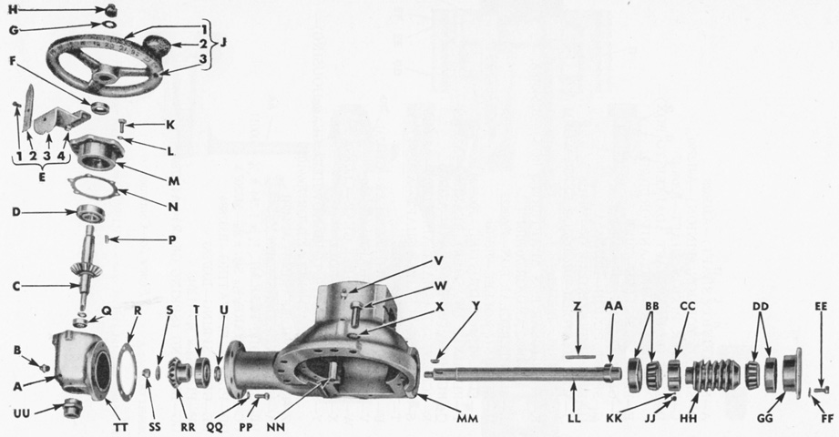
The elevating mechanism E9897, on the other hand, used an adjusting nut on the cone worm. A. Screw, set (shaft adapter). B. Fitting, lubricating, ⅛-27NPT, male. C. Shaft, handwheel gear. D. Bearing, ball. E. Index, handwheel, assembly. 1. Screw, rd-hd., no. 10-32NF-2 x ½. 2. Pointer, index. 3. Bracket, index. 4. Nut, safety, no. 10-32NF-2. F. Seal, oil, type ML, ¾ x 1.254 x ⅜. G. Washer, plate, ½" (1.3cm). H. Nut, safety, ½-20NF-3. J. Handwheel, assembly. 1. Body, handwheel. 2. Knob, handwheel. 3. Shaft, handwheel. K. Screw (bearing retainer); screw, cap, ¼-28NF02. L. Washer, lock ¼" (.64cm). M. Retainer, bearing. N. Shim (retainer to handwheel gear housing). P. Key, square 3/16 sq. x ⅝. Q. Bearing, ball. R. Shim (box to housing). S. Washer (worm gear shaft). T. Bearing, ball. U. Washer (worm gear shaft). V. Fitting, lubricating, ⅛-27NPT, male. W. Screw, cap, ½-20NF02 x 1¼. X. Washer, lock, ½" (1.3cm). Y. Key, Woodruff, 5/32 x ⅝. Z. Key, square, 3/16 sq. x 2. AA. Seal, oil, type ML, ⅞ x 1.756 x 7/16. BB. Bearing, roller. CC. Nut, adjusting. DD. Bearing, roller. EE. Screw, cap, ¼-28NF-2 x ¾. FF. Washer, lock, ¼" (.64cm). GG. Retainer, bearing; shim (retainer to bearing). HH. Worm, cone. JJ. Screw (adjusting nut). KK. Pad (adjusting nut). LL. Shaft, worm gear. MM. Box, elevating gear. NN. Dowel (elevating mechanism assembly). PP. Screw, cap, ¼-28NF-2 x ¾; screw (handwheel gear housing). QQ. Washer, lock, ¼" (.64cm). RR. Pinion, worm shaft. SS. Nut, safety, ⅜-24NF-3. TT. Housing, handwheel gear. UU. Adapter, flexible shaft. (Picture from TM 9-1308 Ordnance Maintenance--76-mm Guns M1A1C and M1A2; Gun Mount M1 and Combination Gun Mount M62 for Combat Vehicles.)
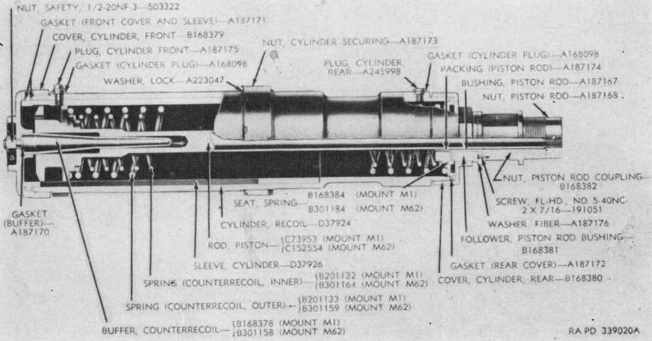
A cross-section of a recoil cylinder assembly is drawn here. The recoil mechanism D82250 used in the combination gun mount M62 was similar to the recoil mechanism D37925 found in the gun mount M1 of the 76mm GMC M18, and both are detailed in the image. When the gun was fired, the gun was forced backwards, pulling the recoil piston rods to the rear since these were attached to the breech ring. Oil would flow around the piston through grooves in the recoil cylinder sleeve. These throttling grooves were tapered toward the rear, which increased restriction of the oil as the gun moved backward. The rearward movement was arrested by the compression of the recoil springs and the pressure of the oil flowing around the piston head. Normal recoil was 12" (30cm), with a maximum of 14" (36cm). When the rearward motion of the gun was stopped, the now-compressed counterrecoil springs expanded, forcing the piston rod, and consequently the gun, forward. More grooves in the recoil cylinder sleeve controlled forward movement, and these were also tapered to their front ends. The buffer then entered the hole in the front of the piston rod near the end of the counterrecoil cycle, forcing out more oil and cushioning the counterrecoil movement. (Picture from TM 9-1308 Ordnance Maintenance--76-mm Guns M1A1C and M1A2; Gun Mount M1 and Combination Gun Mount M62 for Combat Vehicles.)
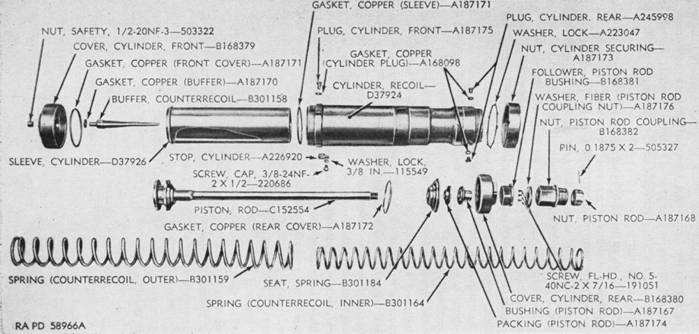
A disassembled recoil cylinder D82250 is diagrammed in this image. Two cylinders were employed on the combination gun mount M62, and each one held ~8 pints (~3.8L) of oil. The inner spring was ~31¼" (~79.38cm) in free length, and at an assembled height of 20¾" (52.71cm) its load specification was 190-220lb (96-100kg). The outer spring was ~29¾" (~75.57cm) in free length, and its load specification was 400-450lb (180-200kg) at an assembled height of 21⅜" (54.293cm). (Picture from TM 9-1308 Ordnance Maintenance--76-mm Guns M1A1C and M1A2; Gun Mount M1 and Combination Gun Mount M62 for Combat Vehicles.)
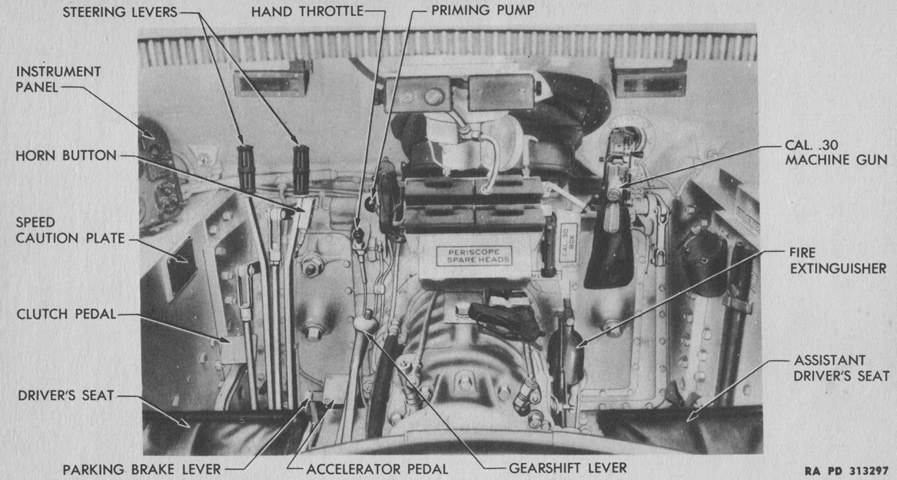
The drivers' controls are labeled in this image. (Picture from TM 9-731AA Medium Tank M4 (105-mm Howitzer) and Medium Tank M4A1 (76-mm Gun).)
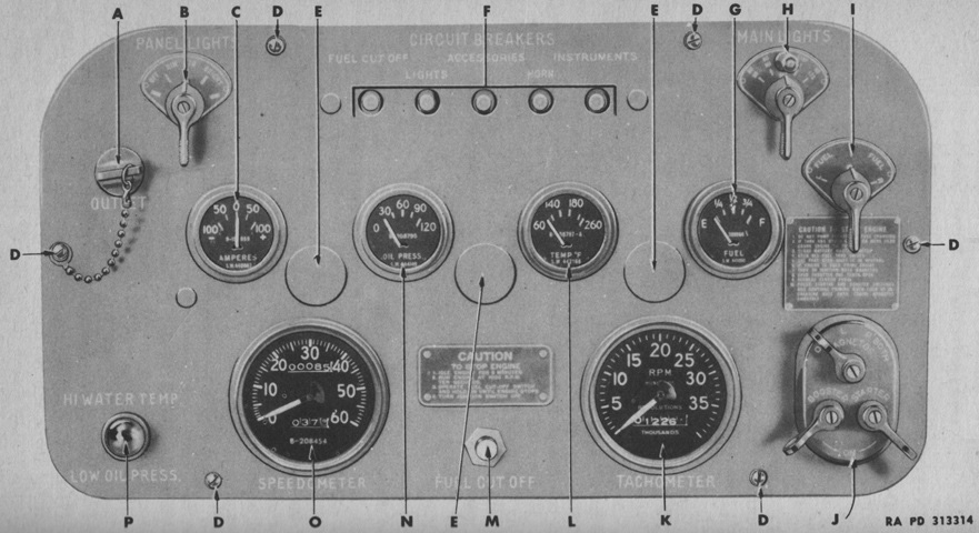
The late-production instrument panel without the fire signal light is shown. A. Utility outlet socket. B. Panel light switch. C. Ammeter. D. Panel attaching screw. E. Panel light cover. F. Circuit breakers. G. Fuel gage. H. Main light switch I. Fuel gage selector switch. J. Cranking motor and magneto switch. K. Tachometer. L. Engine oil temperature gage. M. Fuel cut-off switch. N. Oil pressure gage. O. Speedometer. P. Low oil pressure warning light. (Picture from TM 9-731AA Medium Tank M4 (105-mm Howitzer) and Medium Tank M4A1 (76-mm Gun).)
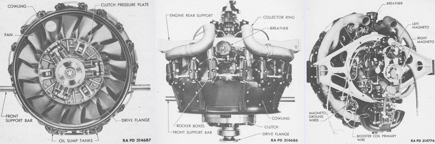
The R975 C4 engine is seen from the front, top, and left rear, respectively. The flywheel end of the engine was considered the front, and the accessory end the rear. Left and right were determined by looking at the engine from the rear. Its dry weight was 750lb (340kg). (Picture from TM 9-1725 Ordnance Maintenance--Ordnance Engine Model R975-C4 (Continental).)
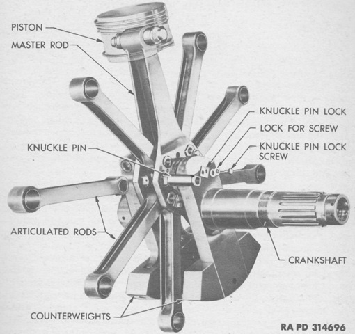
The crankshaft, connecting rods, piston, and knuckle pin assembly is assembled outside of the engine. The pistons were forged aluminum alloy full-trunk types which were numbered clockwise with the top piston being number 1. The master rod was connected to piston 1 and the crankshaft crankpin, while the other pistons were attached to articulated or connecting rods. The crankshaft was a two-piece assembly with counterweights; the rear section's counterweight was attached with loose-fitting pins, which allowed it to act as a dynamic damper to minimize crankshaft vibration. (Picture from TM 9-1725 Ordnance Maintenance--Ordnance Engine Model R975-C4 (Continental).)
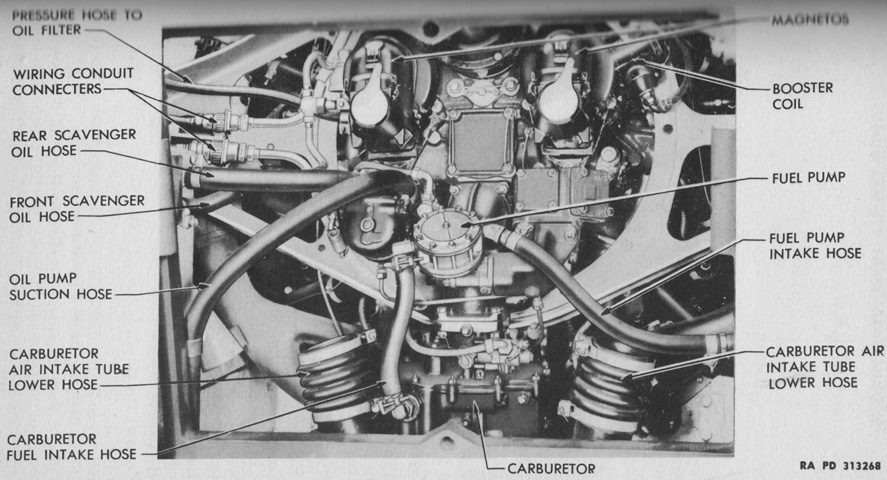
The engine is shown here through the rear hull doors, with the intake tubes removed for clarity. (Picture from TM 9-731AA Medium Tank M4 (105-mm Howitzer) and Medium Tank M4A1 (76-mm Gun).)
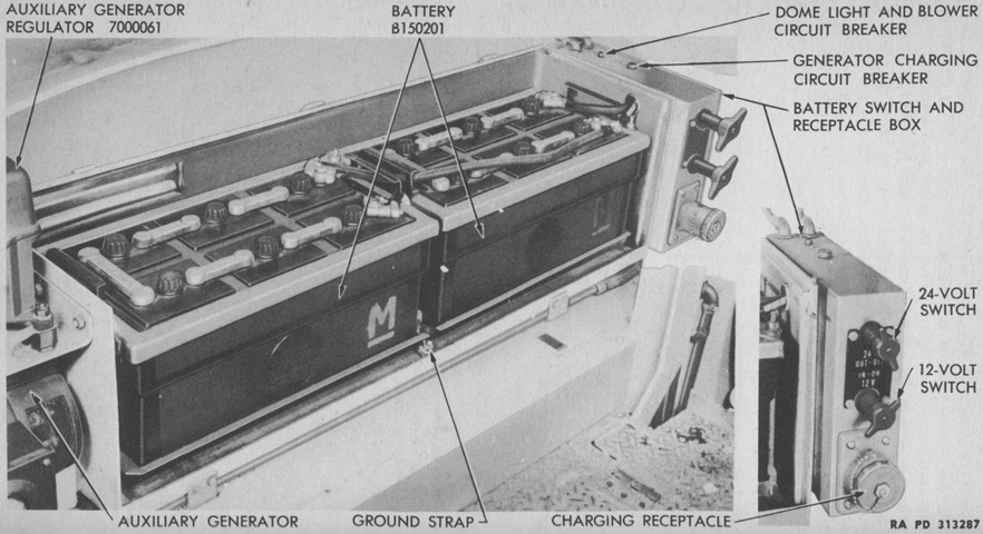
With ammunition stowage being moved to the floor, the batteries were instead installed in a box in the left sponson, which is seen here with its cover removed. The two 12-volt batteries were connected in series to the 24-volt switch on the battery switch box, and a separate lead from one battery supplied voltage to the 12-volt switch for the radio circuit. (Picture from TM 9-731AA Medium Tank M4 (105-mm Howitzer) and Medium Tank M4A1 (76-mm Gun).)
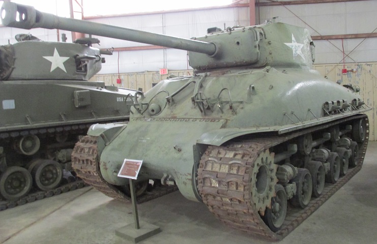
This is one of the 1465 M4A1(76)Ws fitted with horizontal volute spring suspension, and it is wearing single-pin steel T66 tracks. Spare track shoes are stowed on the fenders. The shock absorbers are mounted above the bogies horizontally.
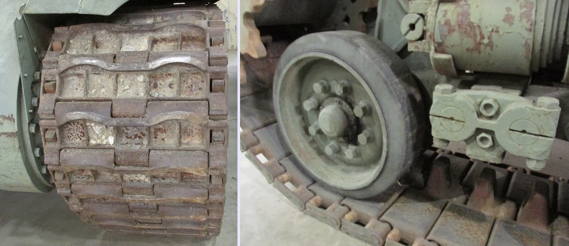
Further details of the T66 track are shown here. Single-pin track was relatively rare on American tanks at this time. As seen on the right, the rear face of the track was steel as well, which was more wearing on suspension components versus rubber or rubber-backed track. The horizontal volute spring of the forward bogie is visible in this image.
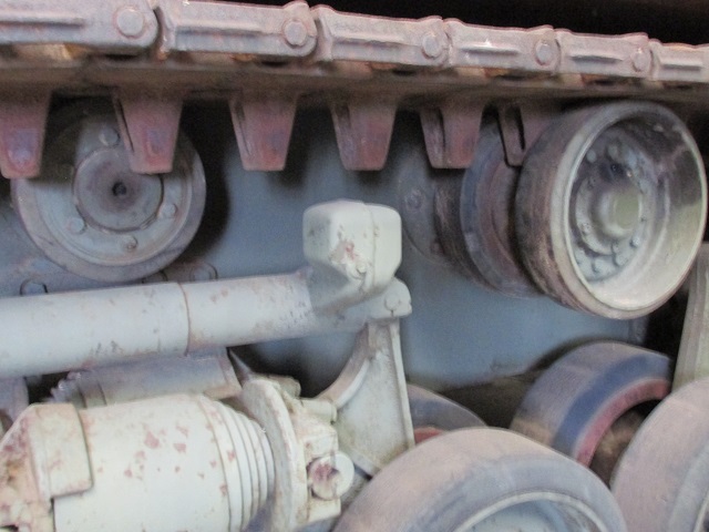
Both types of return roller can be seen in this picture. There were three of the single rollers supporting only the inner run of the track at the front, center, and rear of the hull, and dual return rollers were placed between the single models.
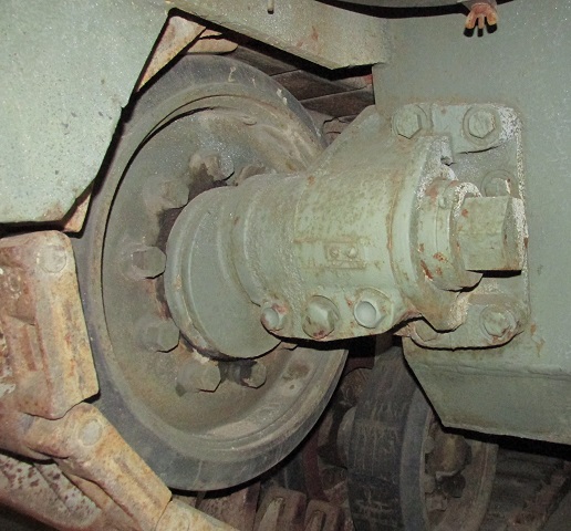
The procedure for adjusting the track tension with HVSS was the same for VVSS, as described above.
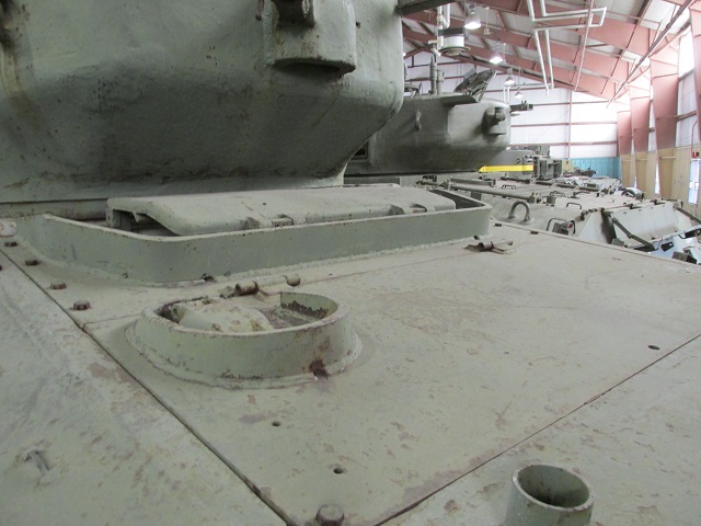
A filler cap for lubricating oil was added in the rear deck plate on later-production radial-engined tanks. The cylindrical socket for holding the idler wheel adjusting wrench has been moved to the top of the rear deck and can be seen at the bottom of the picture. The turret on this tank is equipped with a ventilator at the rear, and its armored exhaust port can be seen on the turret bustle; the stowage pintle for the .50cal machine gun is welded to this port. Early 76mm gun turrets did not feature this ventilator since the medium tank T23 for which the turret was designed had a stronger ventilator between the drivers.
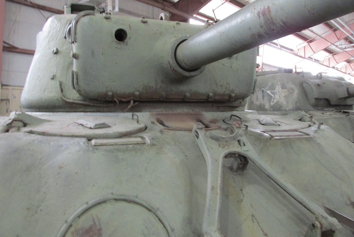
The drivers' larger hatches and the two periscopes for each man can be seen in this image. A ventilator was mounted between them; a cover for the ventilator was not present on early vehicles.
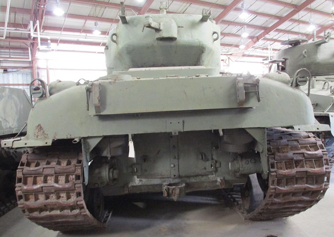
The shallow horseshoe shape originally found in the rear armor eventually was leveled out to improve protection for the air cleaners; triangular armor pieces were also added at the upper corners. The turret ventilator can better be seen in this image, as well as the .50cal MG stowage brackets. The top portion of the MG mounting post is visible on the turret roof.
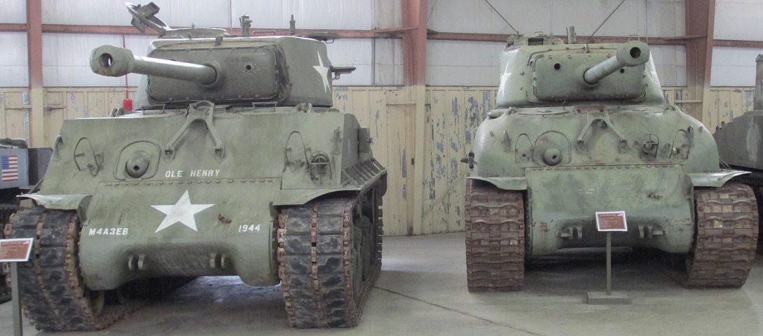
The contours of the welded and cast hull tanks can be easily contrasted in this picture.
The longer final drive covers for tanks with HVSS can be contrasted to the shorter cover on the removed transmission and final drive assembly above. (Picture from ORD 9 SNL G-207.)
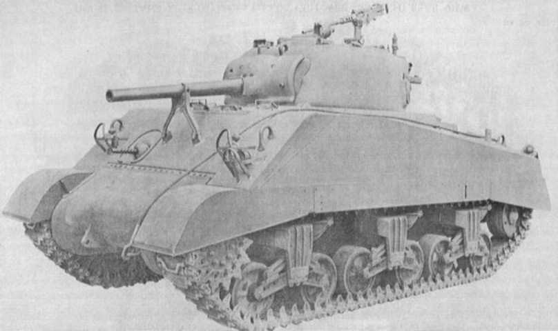
The wet ammunition stowage rendered the applique armor applied over the ammunition racks of earlier tanks redundant. The second set of drivers' periscopes that replaced the earlier direct vision slots are also visible from this angle. (Picture from ORD 9 SNL G-104, Vol. 15.)
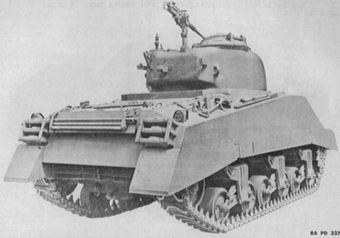
Stowage on the rear of the tank includes track shoes on each side of the hull and gun cleaning equipment on the underside of the crew's blanket rack. The turret rear can also be contrasted with that of earlier 75mm gun tanks. The larger hatches built into the 47° glacis tanks required raising the turret bustle a few inches to allow for clearance. This can be seen here along with the less severe slope of the top of the turret bustle, especially when the antenna mounts are compared. (Picture from ORD 9 SNL G-104, Vol. 15.)
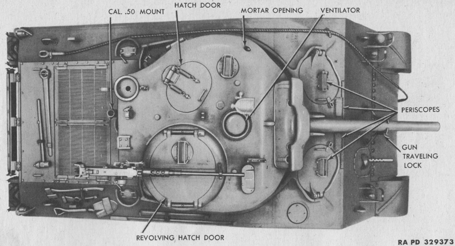
The 47° glacis plate, larger drivers' hatches, and higher-bustle turret are all illustrated from this angle. (Picture from TM 9-759 Tank, Medium, M4A3.)
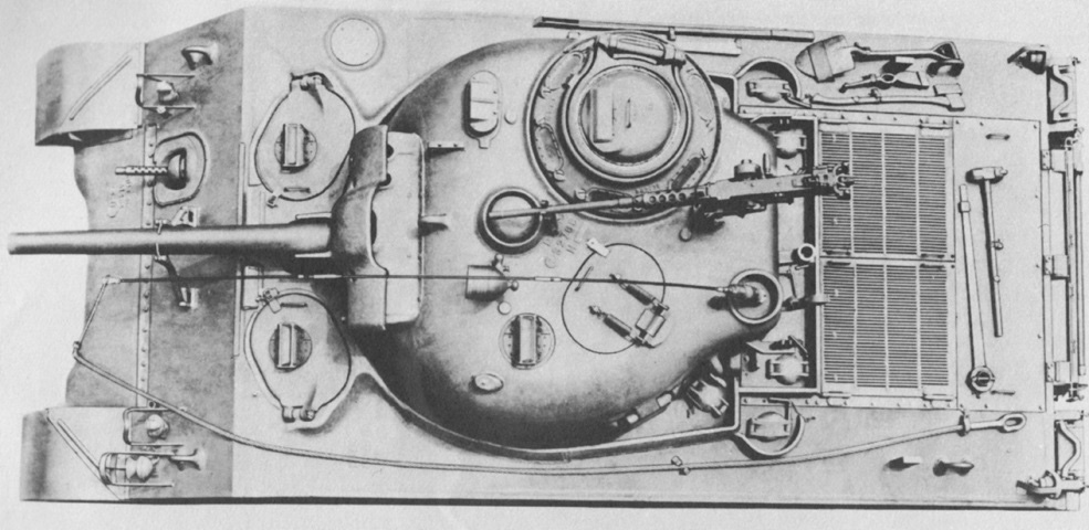
The commander's vision cupola has replaced his split hatch on this tank, and the .50cal machine gun is mounted on the rooftop pintle. Compared to the split hatch, the cupola offered increased vision at the expense of ease of use for the machine gun. The opening for the 2" smoke mortar has been plugged, and a radio antenna is present in the turret bustle mount. (Picture from TM 9-7018 Medium Tank M4A3.)
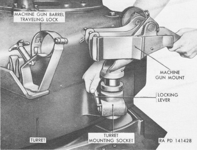
The turret rear stowage points for the .50cal machine gun are labeled here. (Picture from TM 9-7018 Medium Tank M4A3.)
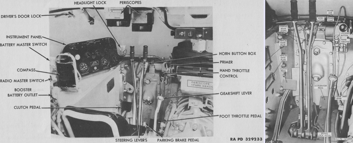
The late-production driver's position is shown in these images, with a broader view on the left and the controls isolated on the right. (Picture from TM 9-759 Tank, Medium, M4A3 and TM 9-7018 Medium Tank M4A3.)
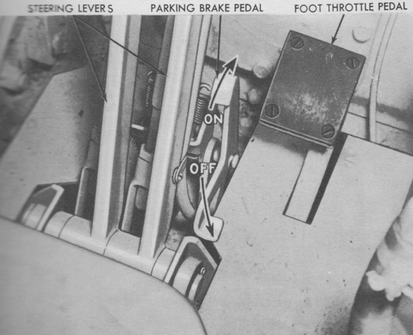
The later-production parking brake control is highlighted here. Early tanks had a transmission-mounted parking brake, but this was replaced by pawl acting on the steering levers that was set and released via a foot pedal. (Picture from TM 9-759 Tank, Medium, M4A3.)
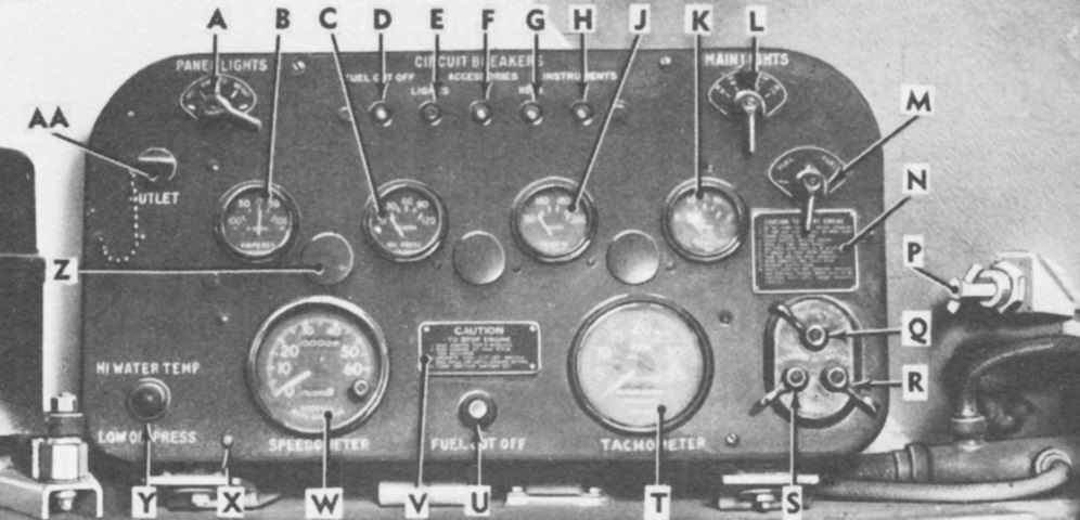
The late-production driver's instrument panel is labeled here. A. Panel light switch. B. Ammeter. C. Oil pressure gage. D. Fuel cut-off circuit breaker. E. Vehicle lights circuit breaker. F. Accessory equipment circuit breaker. G. Horn circuit breaker. H. Instrument panel circuit breaker. J. Engine water temperature gage. K. Fuel gage. L. Main light switch. M. Fuel tank selector switch. N. Engine start caution plate. P. Head light lock. Q. Ignition switch. R. Starter switch. S. Booster switch (not used). T. Tachometer. U. Fuel cut-off switch. V. Engine stop caution plate. W. Speedometer. X. Instrument panel mounting cap screw. Y. High water temperature and low-oil-pressure warning light. Z. Panel light covers. AA. Utility outlet. (Picture from TM 9-7018 Medium Tank M4A3.)
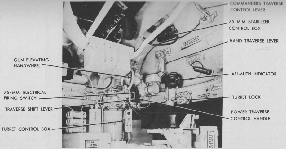
The gunner's controls are shown in this picture, and the box of 75mm ready rounds is labeled on the floor. (Picture from TM 9-759 Tank, Medium, M4A3 and TM 9-7018 Medium Tank M4A3.)
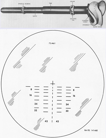
The telescope M70F was a 3x, erect-image type with a field of view of 12°19'. It was 22½" (57.2cm) long. The reticle pattern was graduated for the armor-piercing capped M61 projectile with a 2,030 ft/sec (619m/s) muzzle velocity and a 0.3-mil jump. The center of the cross represented zero range or deflection, and was used when boresighting. Each vertical line and space represented 200 yards (180m) range, while each horizontal line and space represented 5 mils deflection. (Picture from TM 9-7018 Medium Tank M4A3.)
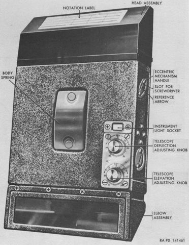
The periscope M4A1 with telescope M38A2 was similar to the periscope M4 with telescope M38 except that provision for an instrument light was added, and the reticle was changed to the one found on the telescope M70F. (Picture from TM 9-7018 Medium Tank M4A3.)
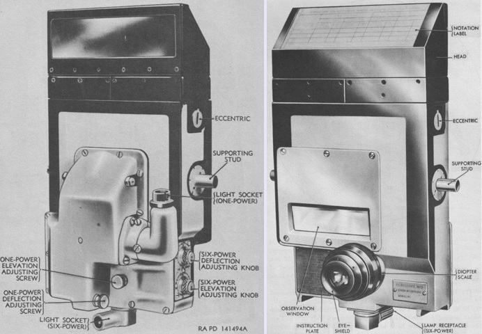
The periscope M10C contained both 1x and 6x optical systems. The 1x system had a horizontal field of view of 42°10', and a vertical field of view of 8°10', while the 6x field of view was 11°20'. (Picture from TM 9-7018 Medium Tank M4A3.)
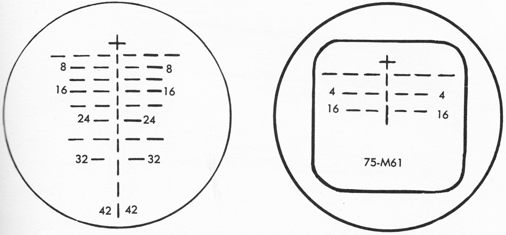
The reticle pattern for the 6x system of the periscope M10C, similar to that found in the telescope M70F, is drawn on the left, with the 1x reticle on the right. (Picture from TM 9-7018 Medium Tank M4A3.)
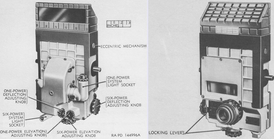
The periscope M16F replaced the M10C, and also contained both a unity and a 6x optical system. The 6x elevation and deflection adjusting knobs were enlarged and provided with positive action locking levers to prevent accidental turning. The knobs were located on the left side and the bottom of the periscope. Scales graduated in ~½-mil increments were used to register boresight adjustments. The light socket was also moved, and light transmission to the reticle was via a plastic rod. The reticles were the same as those in the periscope M10C. (Picture from TM 9-7018 Medium Tank M4A3.)
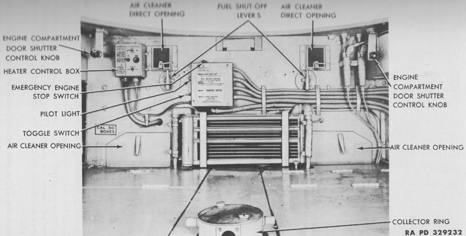
Fixtures on the engine bulkhead are labeled; the floor ammunition bins can be seen in the foreground. (Picture from TM 9-759 Tank, Medium, M4A3.)
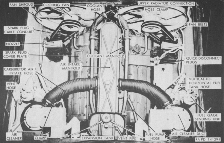
The engine is installed in the vehicle in this image. The front of the tank is to the bottom of the picture. Early tanks had the air cleaners mounted on the fighting compartment side of the engine firewall. (Picture from TM 9-7018 Medium Tank M4A3.)
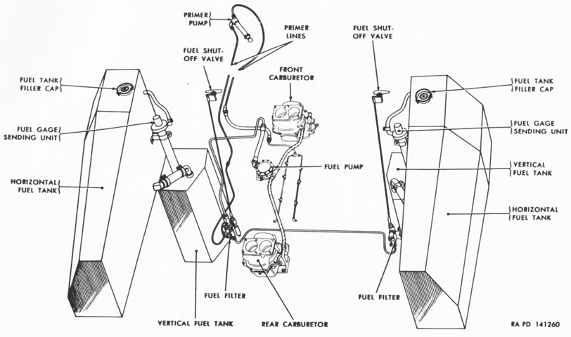
In late-production tanks, the fuel system was changed to incorporate a second fuel filter, while the shutoff valves were reduced to two in number. (Picture from TM 9-7018 Medium Tank M4A3.)
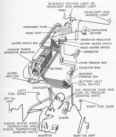
With the advent of wet ammunition stowage in the hull floor, the batteries were moved to the left sponson. A single generator and generator regulator was used instead of the pair of each in earlier tanks. (Picture from TM 9-7018 Medium Tank M4A3.)
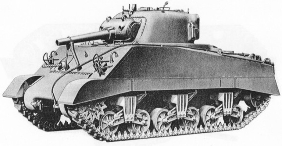
The shorter, thicker barrel on this tank's ordnance, the lifting eyes on the upper lip of the ordnance shield, the large screws evenly spaced around the ordnance, and the location of the travel lock indicate that it is a 105mm howitzer tank. (Picture from ORD 9 SNL G-104, Vol. 6, 11, and 14.)
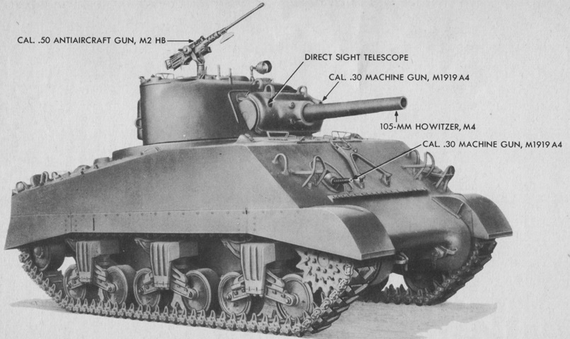
The weapons of a 105mm howitzer tank are labeled. (Picture from TM 9-731AA Medium Tank M4 (105-mm Howitzer) and Medium Tank M4A1 (76-mm Gun).)
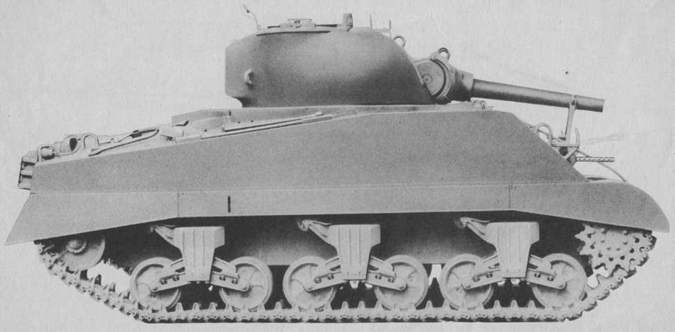
Compared to 75mm gun tanks, the 105mm howitzer shield was thicker and protruded a larger distance from the turret front. The turret itself was similar to the 75mm gun turret found on tanks with the 47° glacis. (Picture from TM 9-731AA Medium Tank M4 (105-mm Howitzer) and Medium Tank M4A1 (76-mm Gun).)
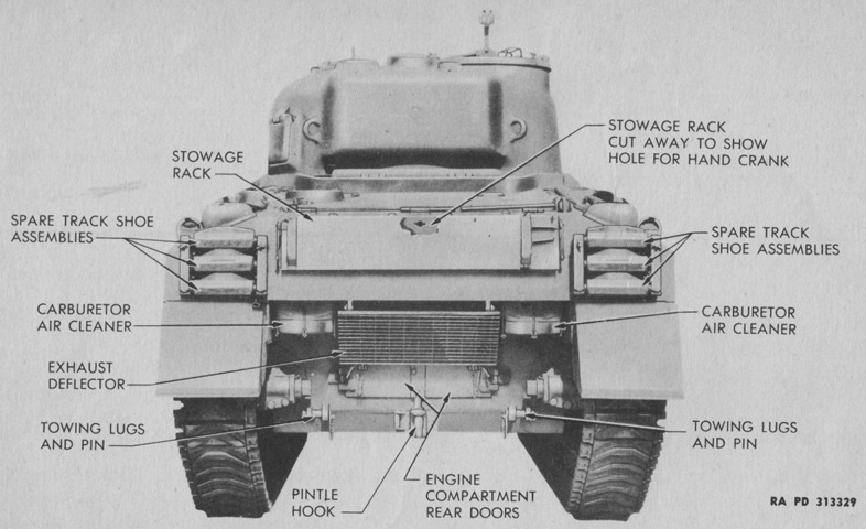
From behind, the second turret ventilator is visible adjacent to the commander's position. (Picture from TM 9-731AA Medium Tank M4 (105-mm Howitzer) and Medium Tank M4A1 (76-mm Gun).)
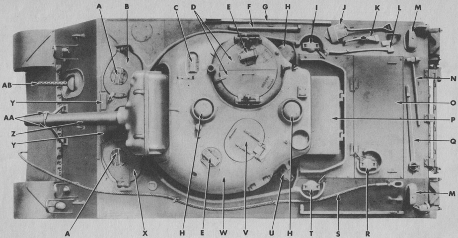
The top of the tank is shown here. A. Periscope. B. Assistant driver's hatch door. C. Sighting device. D. Turret hatch doors. E. Periscope. F. Mattock handle. G. Crowbar. H. Ventilator. I. Right fuel tank filler cap cover. J. Shovel. K. Mattock. L. Ax. M. Grouser compartment scoop. N. Sledge hammer. O. Engine compartment cover, rear. P. Engine compartment air inlet grille cover. Q. Track adjusting wrench. R. Engine oil tank filler cap cover. S. Towing cable. T. Left fuel tank filler cap cover. U. Auxiliary generator fuel tank filler cap cover. V. Loader's escape hatch. W. Turret. X. Driver's hatch door. Y. Periscope holder. Z. 105-mm gun. AA. Gun traveling lock. AB. .30 cal. gun. (Picture from TM 9-731AA Medium Tank M4 (105-mm Howitzer) and Medium Tank M4A1 (76-mm Gun).)
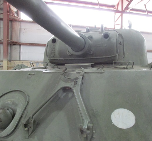
The howitzer travel lock is mounted lower on the upper hull front plate than that for the 75mm gun, which can be easily seen when its location vis-à-vis the bow machine gun is compared with the gun travel lock of the 75mm gun tank above. An attachment for a dust cover can be seen ringing the howitzer shield and the turret front. The howitzer shield features lifting hooks at the top and large screws at the base of the ordnance. The drivers' hatches with their periscopes can be seen, and their increased width compared to earlier vehicles made exiting easier. The hull ventilator between the drivers is fitted with a cover.
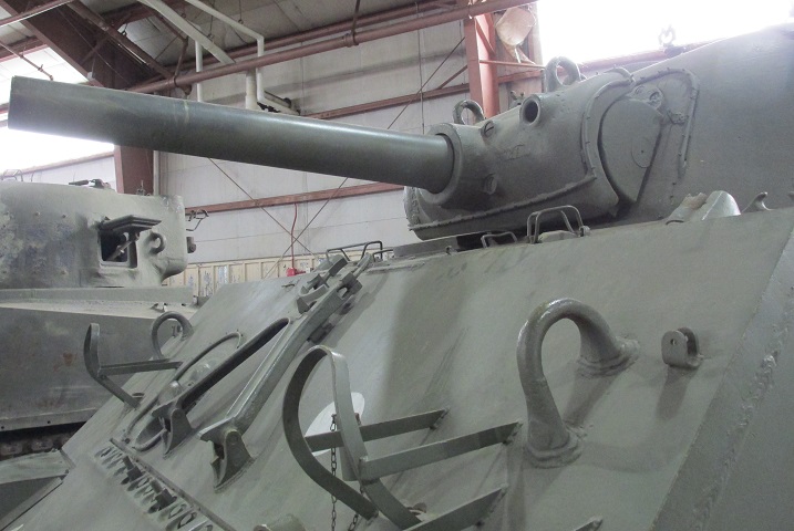
The tall hinge associated with the large drivers' hatches is apparent at the driver's station; the turret bustle was raised in order to clear these hinges. Note the double-ended bolts in the final drive and differential housing in front of the howitzer travel lock; these were part of the equipment to attach the tank mounting bulldozer M1.
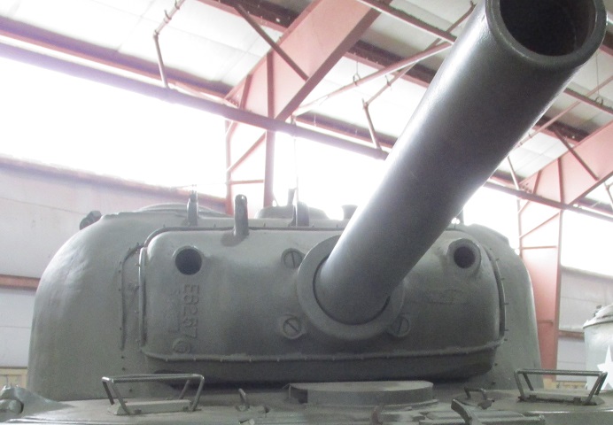
The large aperture in the howitzer shield's right side was for the gunner's sighting telescope, while the opening in the left of the shield was for the coaxial .30cal machine gun.
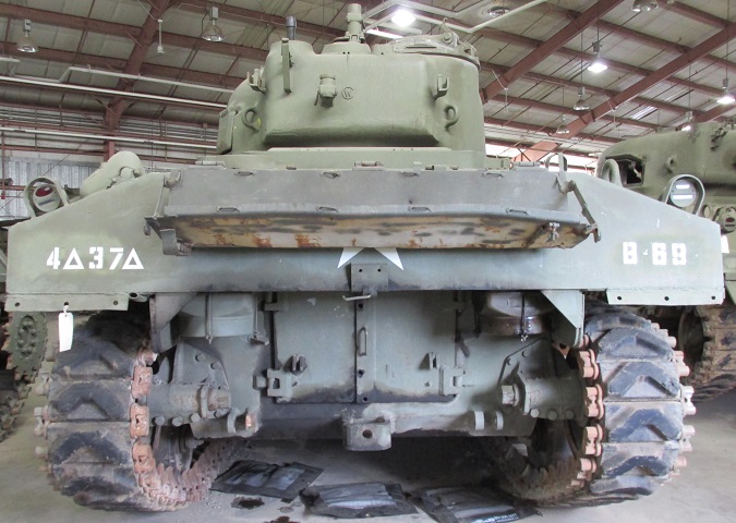
The rear hull plate has been extended to eliminate the shallow horseshoe shape in order to further protect the engine air cleaners, and supplementary armor has been installed around the air cleaners. The exhaust pipe for the auxiliary generator engine can be seen just outboard of the left air cleaner armor. A difference in howitzer turrets versus 75mm gun turrets was an additional ventilator at the rear, the opening for which can be seen between the commander's cupola and the antenna mount. The base of the .50cal machine gun mounting post was therefore designed to fit over top of this ventilator. Note that on this tank the right-hand air scoop over the track grouser compartment is missing.
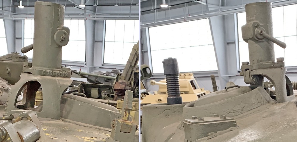
The turret roof .50 caliber machine gun mount is seen from the left front and right rear on the left and right, respectively. The post could fold to the rear when not needed, and the base that raised the mount over the turret ventilator was a three-legged affair.
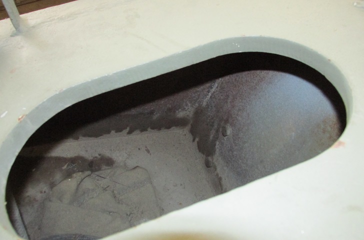
The interior of the open grouser compartment is shown here. The thickness of the hull roof armor can be seen as well.
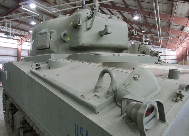
The late-production radial engine deck is illustrated here, with an additional filler cap for lubricating oil on the central deck plate. Fuel fillers are on the sloping sides on either side of the shrouded air intake, and a bracket for aiming stakes and howitzer cleaning rods is below the hull lifting eye.
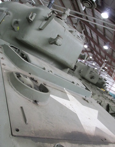
The oil filler cap can be better seen from this angle, and the lip of the base of the .50cal machine gun mounting post can just be made out above the turret ventilator.
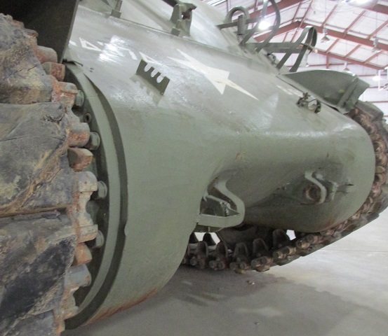
The contours of the sharp-nosed single-piece final drive and differential cover are shown here.
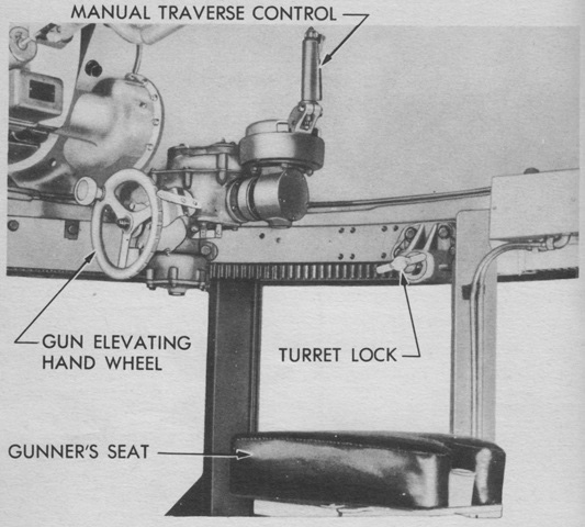
The gunner of howitzer tanks was initially provided only with manual traverse. (Picture from TM 9-731AA Medium Tank M4 (105-mm Howitzer) and Medium Tank M4A1 (76-mm Gun).)
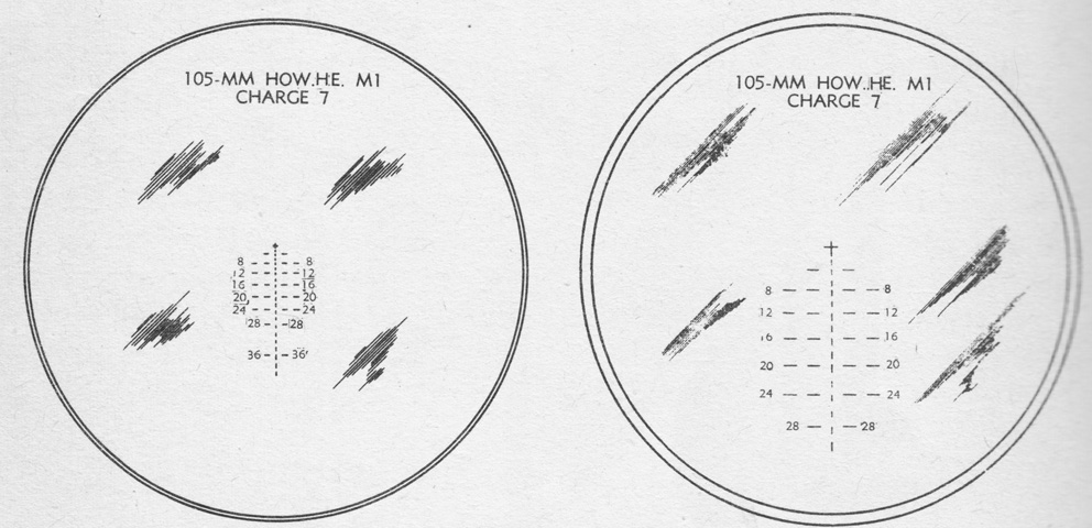
The reticles for the gunner's telescope M72D and telescope M77C in the periscope M4A1 are shown on the left and right, respectively. The M72D was graduated for the high-explosive shell M1 fired at charge 7 with a muzzle velocity of 1,500 ft/sec (460m/s) and a 0.2 mil jump. The cross was at zero range and deflection. The reticle for the M77C was similar. (Picture from TM 9-731AA Medium Tank M4 (105-mm Howitzer) and Medium Tank M4A1 (76-mm Gun).)
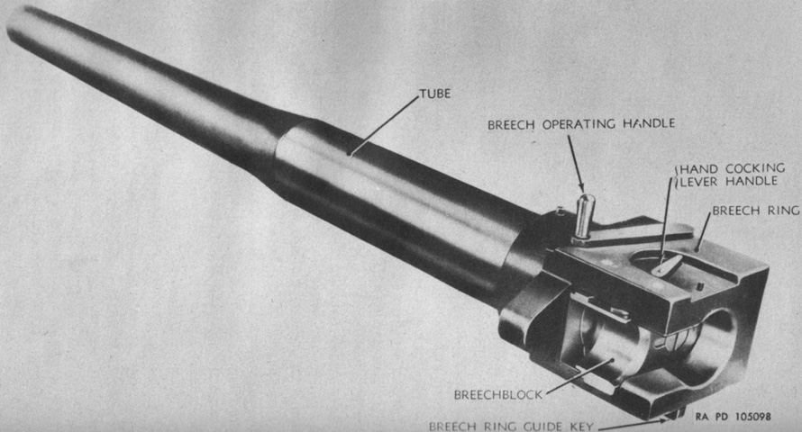
The 105mm howitzer M4 consisted of a tube which screwed into the breech mechanism and was locked in place by a breech ring lock screw. The complete howitzer weighed 1,140lb (517kg) and was 101.3" (257.3cm) long from the muzzle to the rear face of the breech ring. The tube had an estimated accuracy life of 20,000 rounds. (Picture from TM 9-324 105-mm Howitzer M4 (Mounted in Combat Vehicles).)
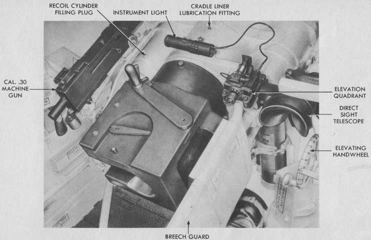
The breech of the 105mm howitzer and coaxial machine gun are shown here. The elevation handwheel featured twenty-five labeled notches, each of which represented 1 mil of elevation or depression. The horizontal sliding wedge breechblock operating handle can be seen atop the breech; the latch on the front of the handle was squeezed to release the handle, then the lever was pulled to the rear and the right to open the breech, which lacked any semiautomatic function. Upon loading, the howitzer shell would slightly move the handle as the lip of its case struck the extractor. This was the signal to close the breech, pushing the operating handle forward until it latched. (Picture from TM 9-731AA Medium Tank M4 (105-mm Howitzer) and Medium Tank M4A1 (76-mm Gun).)
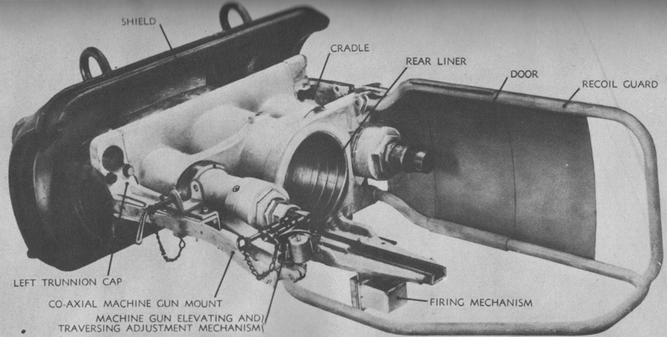
The combination gun mount M52 is seen from the left rear with the howitzer absent. The mount weighed 1,147lb (520.3kg) and with the howitzer mounted was 116" (295cm) long including the recoil guard. (Picture from TM 9-324 105-mm Howitzer M4 (Mounted in Combat Vehicles).)
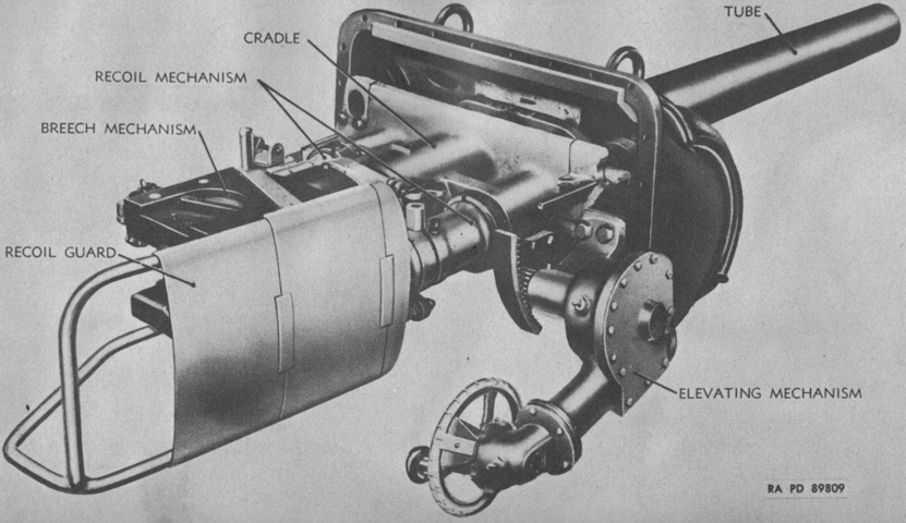
The combination gun mount M52 is shown from the opposite side with the howitzer installed. (Picture from TM 9-324 105-mm Howitzer M4 (Mounted in Combat Vehicles).)
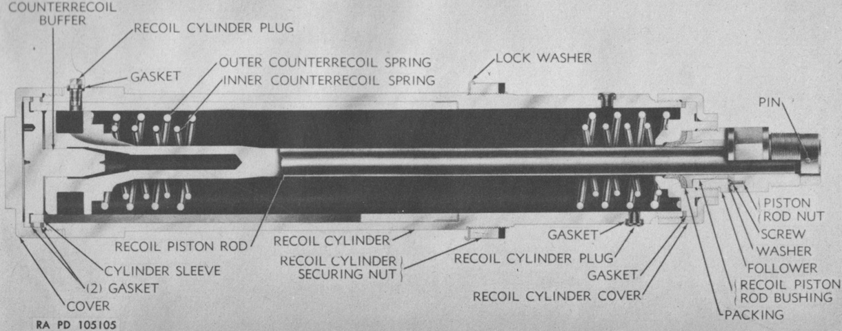
A cross-section of one of the two hydrospring recoil cylinders is drawn here. Each cylinder contained 9 pints (4.259L) of oil, and the normal and maximum recoil lengths were 13" (33cm) and 14" (36cm), respectively. When the howitzer was fired, the tube and breech ring were driven to the rear. The recoil piston rod in each cylinder moved with the breech, while the cylinder itself remained stationary and fastened to the cradle. Oil in the cylinder was forced around the piston through grooves in the cylinder sleeve as the piston rod was dragged rearward. The grooves tapered to the rear, increasing resistance as the piston moved. This increased resistance as well as the compression of the counterrecoil springs by the piston would arrest the movement of the howitzer. The compressed counterrecoil springs would then expand, pushing the piston forward and the howitzer back into battery. The counterrecoil buffer entered the hole at the front of the piston rod near the end of the counterrecoil stroke, displacing oil trapped in the hole which was then throttled around the buffer, slowing the counterrecoil movement to prevent shock. (Picture from TM 9-324 105-mm Howitzer M4 (Mounted in Combat Vehicles).)
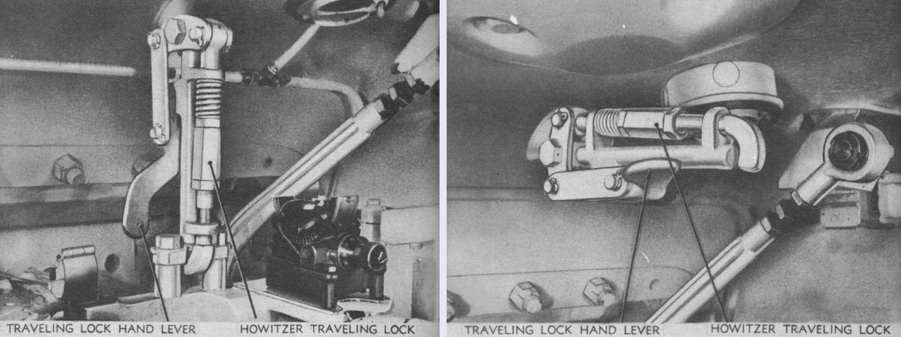
In addition to the travel lock on the hull upper front plate, an internal elevation traveling lock was found in the turret. It is shown engaged on the left and stowed on the right. (Picture from TM 9-324 105-mm Howitzer M4 (Mounted in Combat Vehicles).)
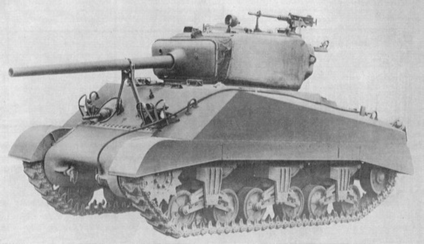
This tank would have similar modifications as the M4A1(76)W above. (Picture from ORD 9 SNL G-104, Vol. 15.)
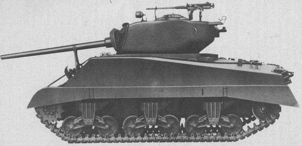
The more pronounced overhang of the 76mm gun is obvious even with the ordnance depressed into the travel lock. (Picture from TM 9-759 Tank, Medium, M4A3.)
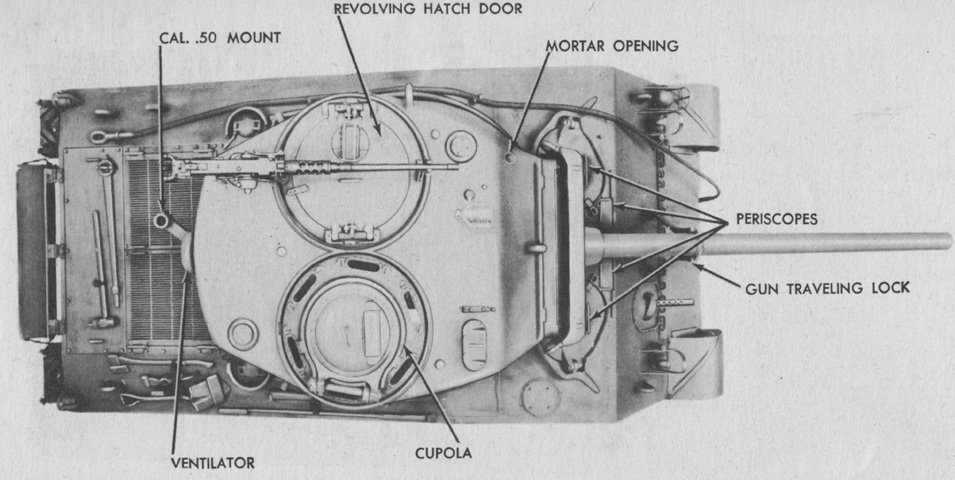
This early turret features the circular split loader's hatch. (Picture from TM 9-759 Tank, Medium, M4A3.)
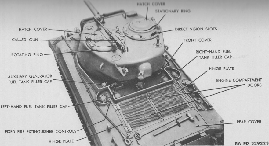
The engine deck and turret top are labeled in this image. Rests for the engine compartment doors have been added to the upper hull sides; the left one is visible outboard of the towing cable, and the other is just inboard of the shovel. (Picture from TM 9-759 Tank, Medium, M4A3.)
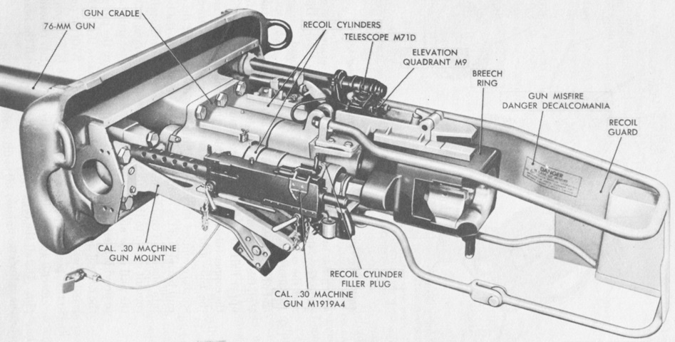
The gun mount M62 is shown here. The complete 76mm gun M1A1C or M1A2 weighed 1,231lb (558.4kg), with the muzzle brake weighing 62lb (28kg). The gun was 163.75" (415.93cm) long overall. (Picture from TM 9-7018 Medium Tank M4A3.)
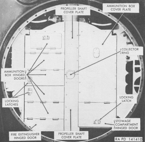
The various lids and compartments in the hull subfloor of a 76mm gun tank can can be seen here. The ammunition boxes on the left featured diagonal stowage, while rounds in the right-side box were stowed horizontally. Ammunition was to be retrieved in the following order: the front half of the racks on the left side of the tank, the rear half of the racks on the left side of the tank, then the horizontal racks on the right side of the tank. The ready rounds were normally reserved for actions where loading speed was paramount, and the horizontal rounds were ideally used to refill the other racks as time permitted. (Picture from TM 9-7018 Medium Tank M4A3.)
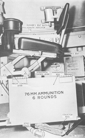
The six-round ready box of ammunition is shown here. The gunner's position is in the background. (Picture from TM 9-7018 Medium Tank M4A3.)
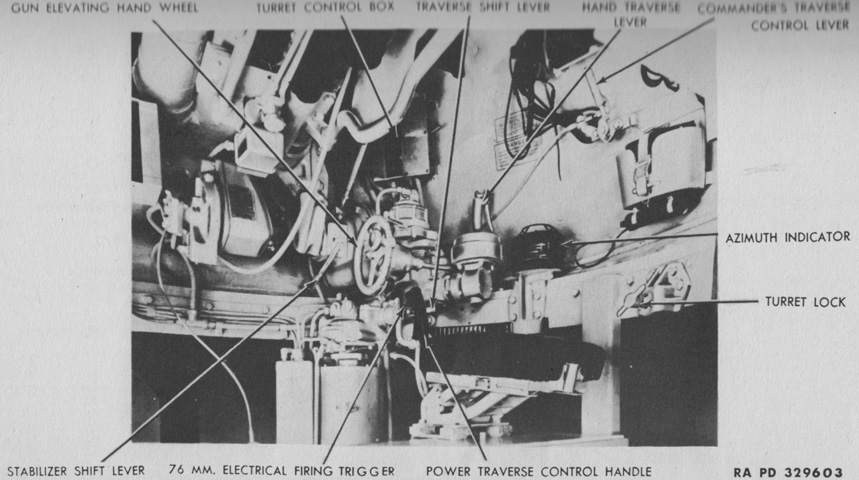
The turret and gun controls are displayed in this picture. (Picture from TM 9-759 Tank, Medium, M4A3.)
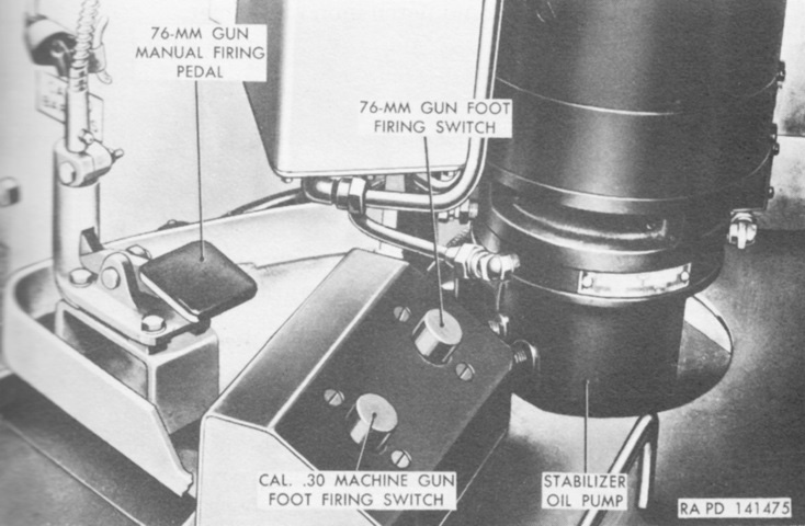
In addition to their hand triggers, gunners in 76mm gun tanks were provided with electrical foot triggers as well as a manual foot firing pedal. (Picture from TM 9-7018 Medium Tank M4A3.)
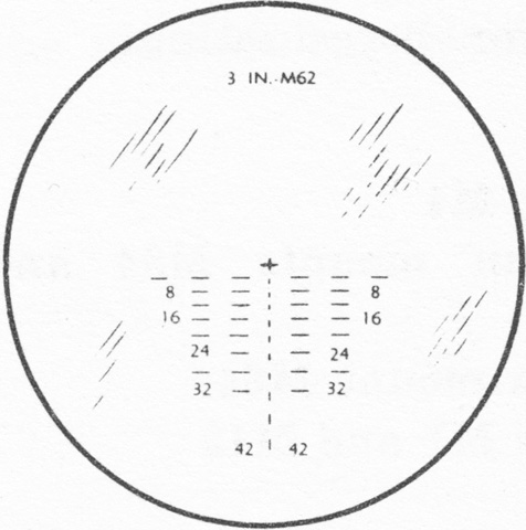
The reticle for the updated telescope M47A2 used in the periscope M4A1 is sketched. (Picture from TM 9-2300 Artillery Matériel and Associated Equipment.)
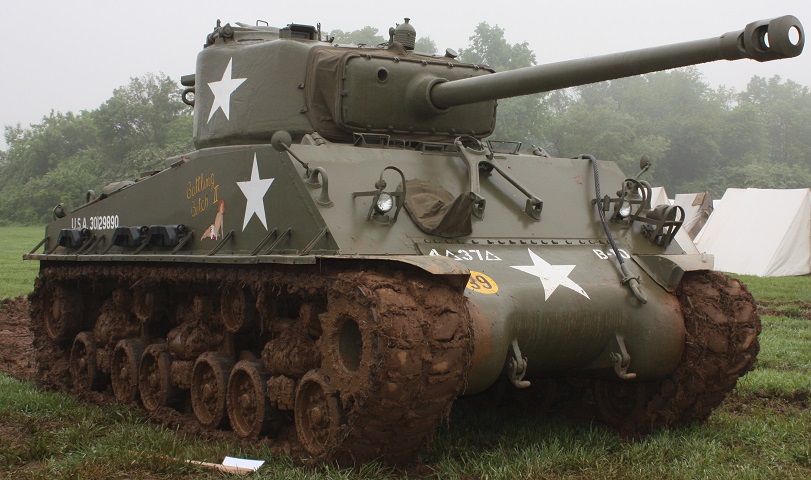
"Battling Bitch II" is one of the 1531 M4A2(76)Ws fitted with horizontal volute spring suspension, and the wide tracks and fenders are immediately obvious compared to the vertical volute spring-suspended tanks. Spare track shoes are stowed on the fenders. This vehicle is armed with the 76mm gun M1A1C or M1A2, both of which were fitted with muzzle brakes, and on the turret roof, the spotlight is mounted and pointed downwards. Compared with the early M4A1 Sherman above, later Sherman tanks are almost unrecognizable. (Photo by Richard S. Eshleman.)
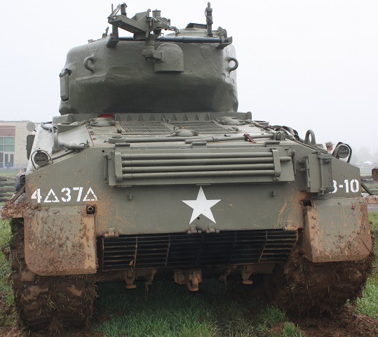
While the front offers few points at differentiating the type of tank, this rear view allows identification. The width of the engine grille doors and location of the fuel, water, and oil filler caps indicate the diesel engine. Note the armored cover behind the engine grille doors over the engine oil gauge referred to above. The exhaust pipe for the auxiliary generator engine can be seen exiting the hole inboard of the left-hand mudguard. Gun cleaning rods are stowed on the blanket roll rack on the hull rear plate, and a sledgehammer and the idler wheel adjusting wrench are stowed on the rear deck aft of the engine grille doors. On the right side of the rear hull plate is mounted an infantry phone box. (Photo by Richard S. Eshleman.)
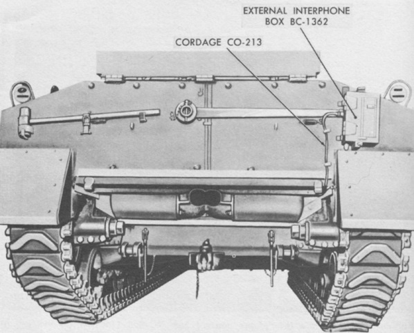
The interphone box and cordage are highlighted in this image. (Picture from TM 9-7018 Medium Tank M4A3.)
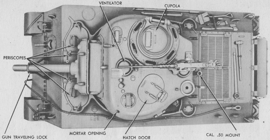
The commander's cupola and oval loader's hatch are present on this turret, and the two turret roof ventilators can also be seen, with the rear one under the .50cal machine gun mount. (Picture from TM 9-759 Tank, Medium, M4A3.)
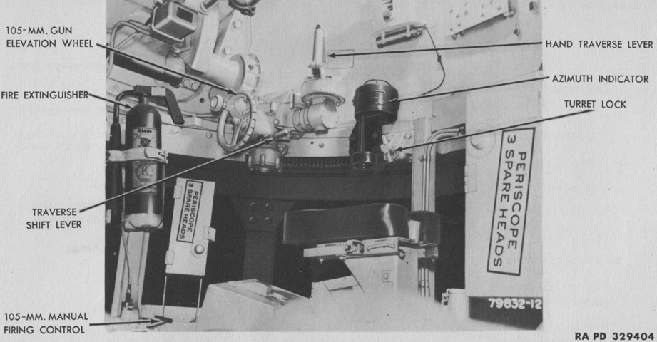
The gunner had not been provided with power traverse at the point this tank was manufactured. A traverse shift lever is present, but instead of changing to power traverse, moving the lever upward shifted the traversing mechanism into neutral position. (Picture from TM 9-759 Tank, Medium, M4A3.)
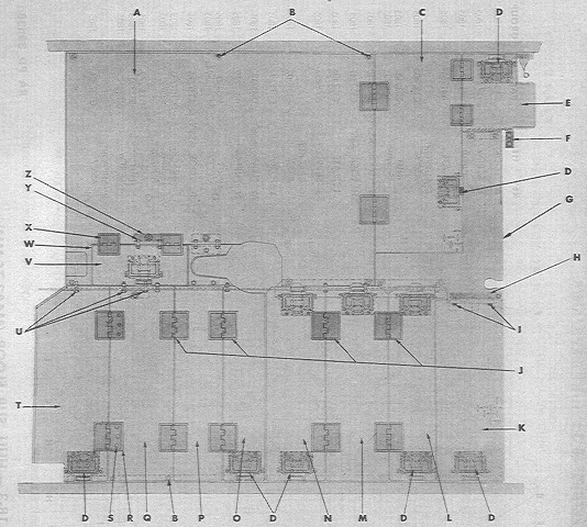
The various lids and compartments in the hull subfloor of a 105mm howitzer tank can can be seen here. (Picture from ORD 9 SNL G-104, Vol. 15.)
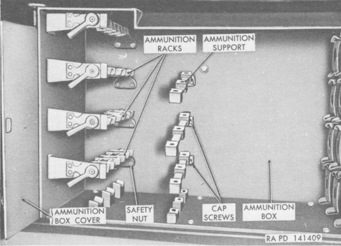
A sponson ammunition box is shown here. The howitzer shells would be stowed horizontally in the box. (Picture from TM 9-7018 Medium Tank M4A3.)
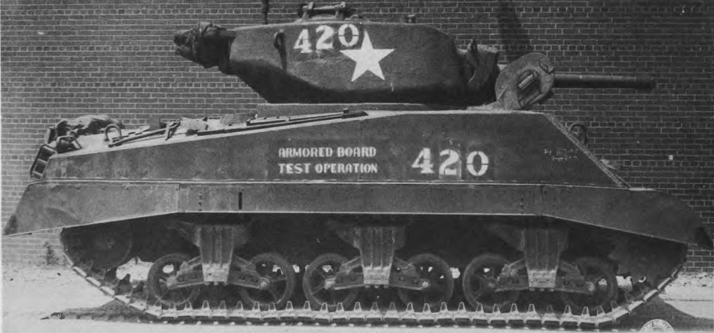
The shape of the heavy new turret mounted on the M4A3E2 can be seen here, and the weld lines for the extra armor applied to the gun shield and hull front can be glimpsed. The commander was provided with a cupola. Extended end connectors have been installed to help lessen the tank's ground pressure. (Picture from Development of Armored Vehicles, volume 1: Tanks.)
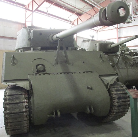
Fixtures such as the headlights and siren have been omitted from the hull front, however the bow machine gun was retained. This tank lacks the extended end connectors on its T48 tracks. The gun mount welded in place to the hull is of course not the original, and likewise this machine has been rearmed with the 76mm gun.
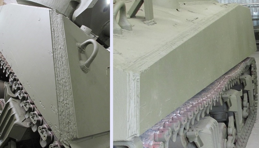
The extra armor added to the tank's upper front hull and sides is apparent when one looks at the joining welds.
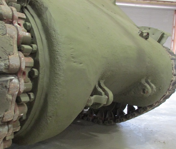
The final drive and differential cover is noticeably sturdier than on non-assault tanks.
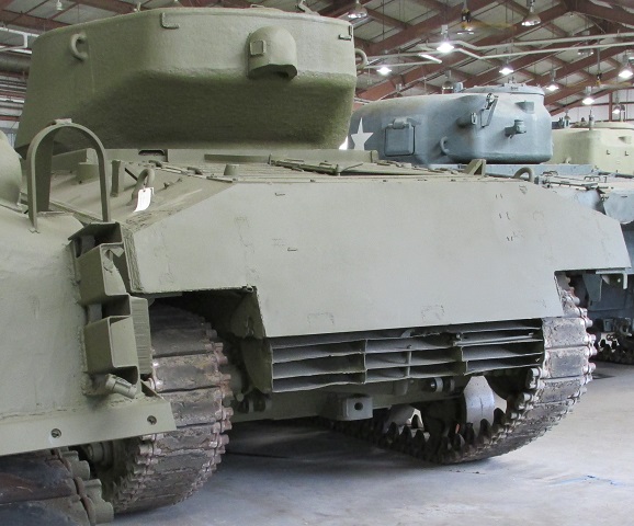
The rear hull armor, however, was unaugmented.
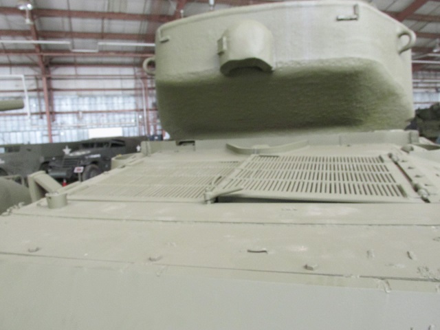
The rear deck also remained the same thickness, with its characteristic full-width air intake grilles.
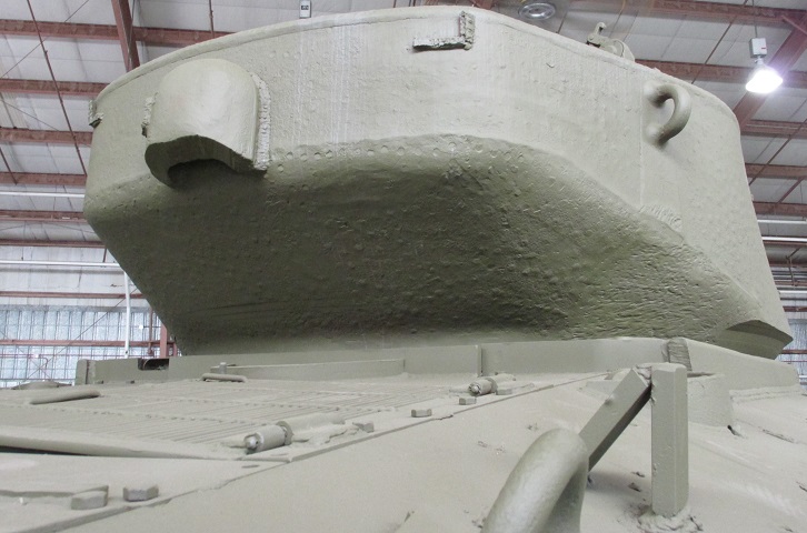
The turret design was based on that of the 76mm gun turret. The ventilator housing is lower relative to the lower edge of the turret rear on the M4A3E2, however, since the extra armor also elongated the turret.
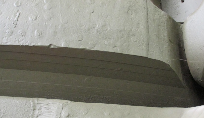
The underside of this turret, cast by the Ordnance Steel Foundry Company, features extensive machining to allow it to clear the hull fixtures. Turrets cast by Union Steel Castings lack this machining and are smoother as they reach down to the hull.
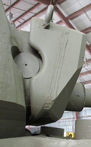
The gun mount T110 was a 76mm gun mount M62 with thick armor welded to its front, and the weld bead for the additional protection can easily be seen in this image. Note that the lower corners of the gun shield had to be angled back to avoid fouling on hull fixtures.
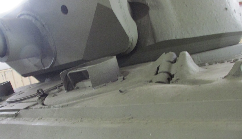
The driver's hatch and periscope with guard can be seen here.
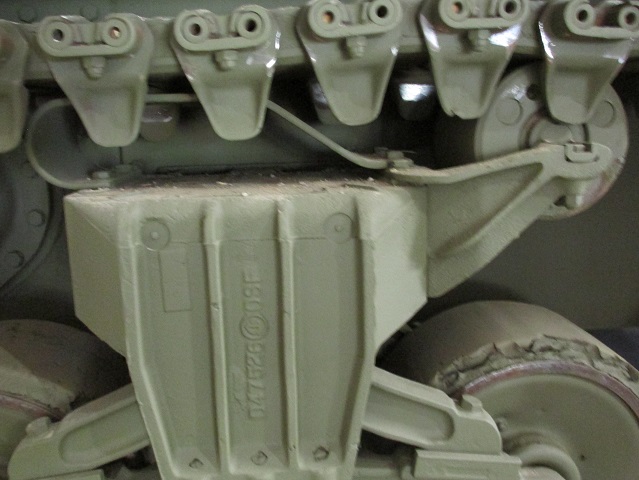
This tank features suspension bogies fitted with the raised arm for the return roller, which helped reduce wear on the track skid from steel track.
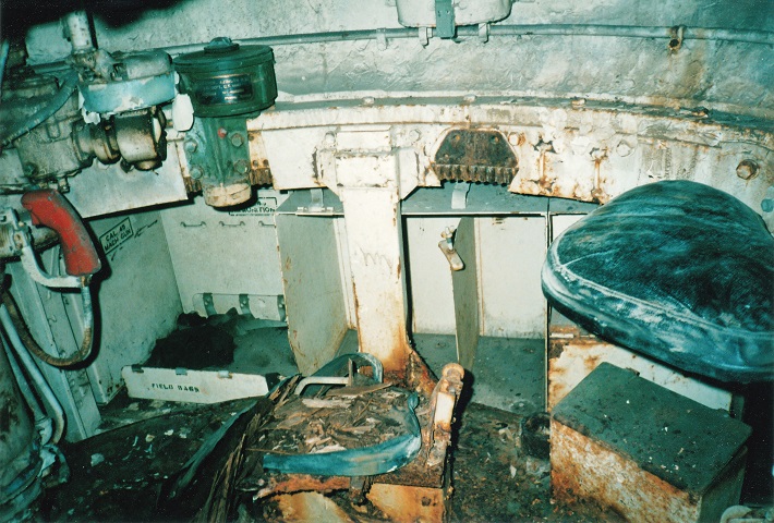
This view is of the right side of the turret. The commander's seat is visible, and the gunner's seat, if present, would be in front of and below the TC's seat. The gunner's red turret traverse handle is near the front of the picture, and the white turret traverse hand lever can just been seen near the top of the picture. The black device near the turret ring is the gunner's azimuth indicator. Stowage in the right sponson included three water cans in the compartment in the center of the picture. The hexagonal hole through which the turret ring is visible would normally be covered by the traverse lock.
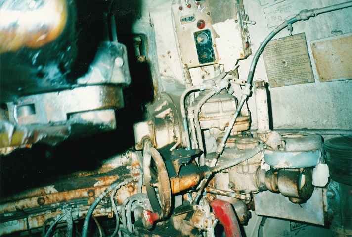
This is a more detailed view of the gunner's station. The azimuth indicator is on the far right, the red turret traverse handle is visible again, and the white traverse hand lever can be seen in front of the azimuth indicator. The elevating handwheel has a red handgrip, and the main gun can be seen in the upper left. The turret control box is positioned above the gunner's controls to the front.
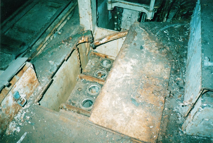
M4A3E2s featured wet ammunition stowage, and an open ammunition rack is illustrated here. The driver's seat is in front of this ammo rack.
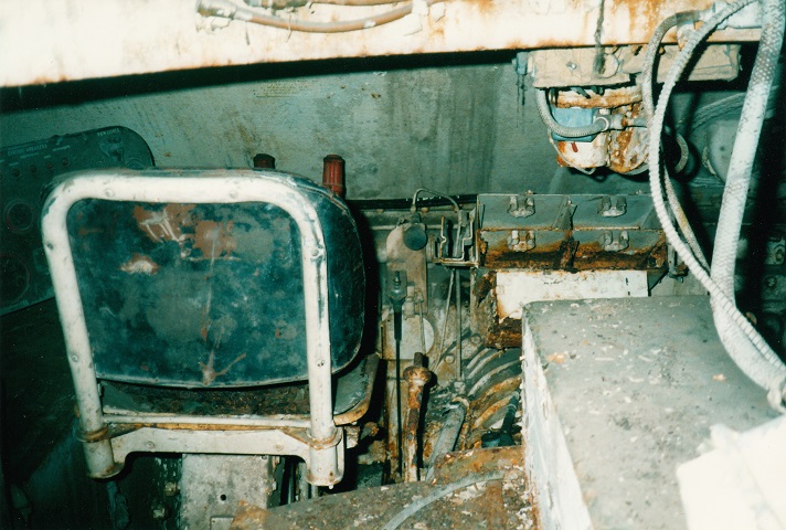
The driver's position is the subject of this photo. The driver and assistant driver were separated by the transmission assembly. The two steering levers can be just seen in front of the driver's seat, and his instrument panel is to the left. The rusted gearshift lever is just to the right of the driver's seat, and the black knob to the right of the steering levers is the hand throttle. The four brackets above the transmission itself were for stowing extra periscopes; spare periscope heads could be stored in the box below the periscopes themselves. Between the drivers on the hull roof is a ventilator fan. The ball mount for the bow machine gun can be seen in the front hull plate on the right of the picture.
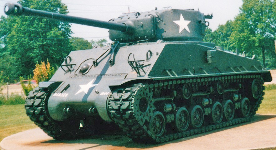
From the front, this M4A3(76)W HVSS is visually virtually identical to the M4A2(76)W HVSS above, although its identity is belied by the posts on the upper hull sides used for supporting the engine air intake grilles when opened. In the center of the 47° glacis is the gun travel lock, and the sharp-nosed single-piece final drive and differential cover is mounted. The tracks on this vehicle are the double-pin T84.
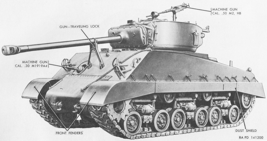
In contrast to the previous machine, this tank has been fitted with sand shields. (Picture from TM 9-7018 Medium Tank M4A3.)
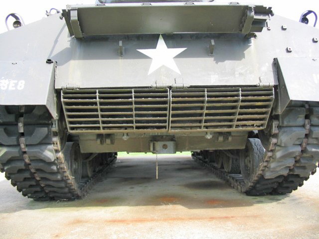
This view shows the later exhaust deflector fitted to the GAA-engined Shermans. It consisted of two armored pieces that could be raised independently. Directly under the blanket rack are supports for the deflectors when they are raised. This tank also has some sections of track mounted incorrectly.
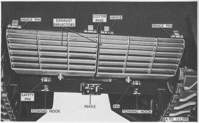
Parts of the deflector and towing equipment are labeled in this image. (Picture from TM 9-7018 Medium Tank M4A3.)
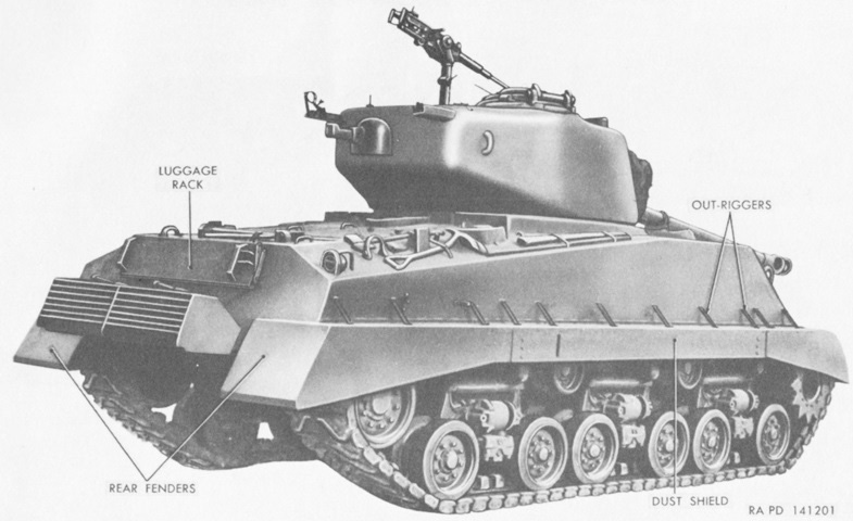
Both halves of the exhaust deflector have been raised and secured to their lugs on the hull rear. (Picture from TM 9-7018 Medium Tank M4A3.)
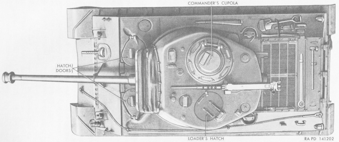
The shape of the 76mm gun turret can be seen from above. (Picture from TM 9-7018 Medium Tank M4A3.)
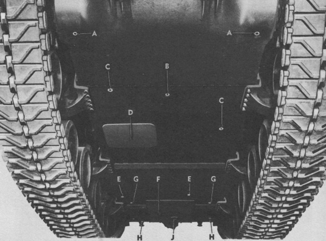
The underside of the hull is shown here, with the front at the top of the image. Attachment of the HVSS bogies to the hull underside can be seen. A. Final drive drain plugs. B. Transmission drain plug. C. Driver compartment drain valves. D. Escape hatch. E. Fighting compartment drain valves. F. Engine compartment access plate. G. Fuel tank drain plugs. H. Engine compartment drain valves. J. Engine oil drain plug. (Picture from TM 9-7018 Medium Tank M4A3.)
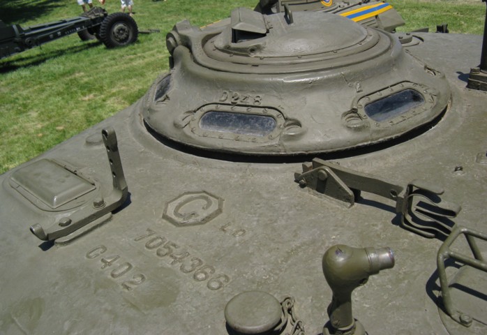
The commander's vision cupola is detailed here. He was provided with a rotating periscope in the cupola door, and six vision blocks ringed the base of the cupola. The revised vane sight is mounted in front of the cupola, and outboard of this is the cover for the gunner's periscope. A stowage clip for the barrel of the roof-mounted machine gun is folded onto the turret roof, and a searchlight mount can be seen towards the bottom right of the image.
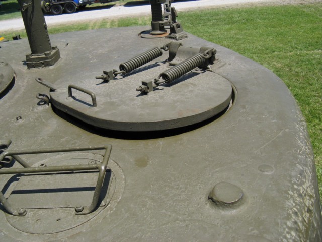
The loader's oval hatch is slightly ajar on this machine. The springs to assist the loader in the hatch's operation are obvious, and a hold-open catch can be seen to the rear in front of the antenna mount. The loader's periscope and guard can be seen in the foreground, and the mounting post for the .50cal MG is in the turret rear between the loader's hatch and commander's cupola.
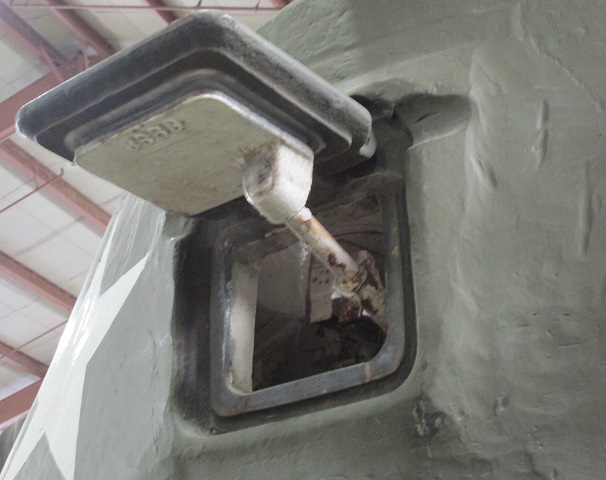
The pistol port is open on this tank, and the mechanism for opening and closing it can be seen.
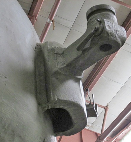
The armored casting for the turret ventilator was substantial, as can be seen here. The welding for the machine gun stowage receptacle is also visible.
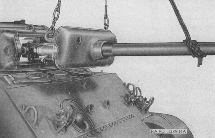
The combination gun mount M62 is being removed from this tank. In contrast to the 75mm combination gun mounts, the M62 did not use separate rotor and gun shields. (Picture from TM 9-1308 Ordnance Maintenance--76-mm Guns M1A1C and M1A2; Gun Mount M1 and Combination Gun Mount M62 for Combat Vehicles.)
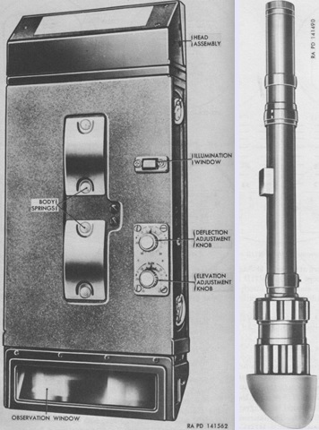
The gunner's periscope M8A1 with telescope M39A2 is on the left, with the telescope M83D on the right. The periscope M8A1 was similar to the M4A1, but was longer (14¾" [37.47cm] versus 11-1/16" [28.0988cm]) and had two clamping knobs at the rear. The M83D was a variable 4x to 8x device with real semifield fields of view of 7°40' at 4x and 4°15' at 8x. The reticle patterns were both identical to that of the telescope M71D, except that of the telescope M39A2 in the periscope M8A1 had "3 in-M62" inscribed at the top instead of "76-M62." (Picture from TM 9-7018 Medium Tank M4A3.)
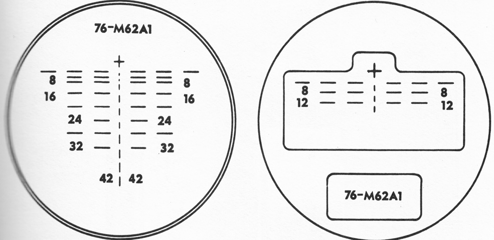
The periscope M16G was a periscope M16F with a new reticle. The periscope M10G was similar to the M10C except for a new reticle and a spacer between the head and body that raised the head and improved the field of view. The 6x reticle for the M16G and M10G is drawn on the left, with the 1x reticle on the right. (Picture from TM 9-7018 Medium Tank M4A3.)
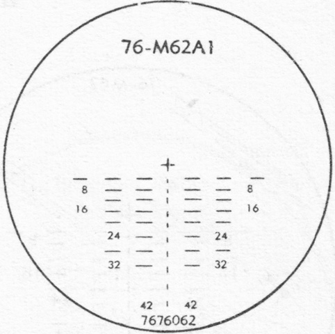
Similarly, the reticle for the gunner's telescope M71P was updated for the 76mm M62A1 projectile. (Picture from TM 9-2300 Artillery Matériel and Associated Equipment.)
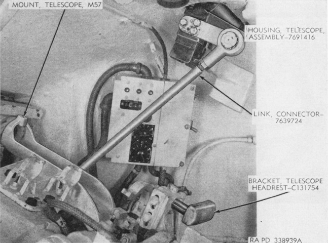
The linkage from the gun mount to the gunner's periscope is seen in this image. The turret control box with the stabilizer adjustment knobs is in the background. (Picture from TM 9-1308 Ordnance Maintenance--76-mm Guns M1A1C and M1A2; Gun Mount M1 and Combination Gun Mount M62 for Combat Vehicles.)
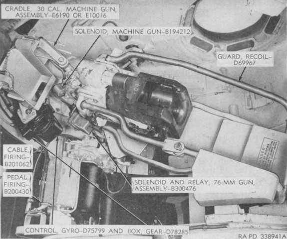
The combination gun mount is illustrated from the loader's side of the turret, but the coaxial machine gun is not present. Note the horizontal orientation of the 76mm gun breech. The commander's cupola can be seen at the upper right of the picture. (Picture from TM 9-1308 Ordnance Maintenance--76-mm Guns M1A1C and M1A2; Gun Mount M1 and Combination Gun Mount M62 for Combat Vehicles.)
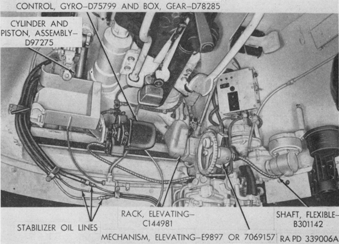
The combination gun mount is shown from the bottom. (Picture from TM 9-1308 Ordnance Maintenance--76-mm Guns M1A1C and M1A2; Gun Mount M1 and Combination Gun Mount M62 for Combat Vehicles.)
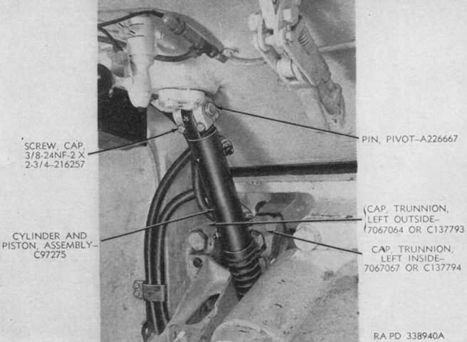
The stabilizer's cylinder and piston connected the upper left corner of the gun mount to the tank's roof. The internal gun travel lock is at the upper right of the image, and the control for the roof-mounted spotlight is at the upper left. (Picture from TM 9-1308 Ordnance Maintenance--76-mm Guns M1A1C and M1A2; Gun Mount M1 and Combination Gun Mount M62 for Combat Vehicles.)
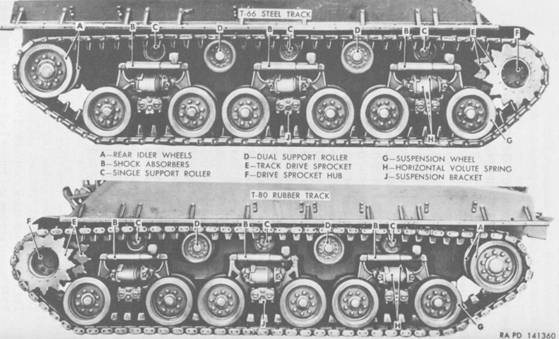
Nomenclature of the horizontal volute suspension system is given in this picture. Note the different center guide shape of the T66 versus T80 tracks. (Picture from TM 9-7018 Medium Tank M4A3.)
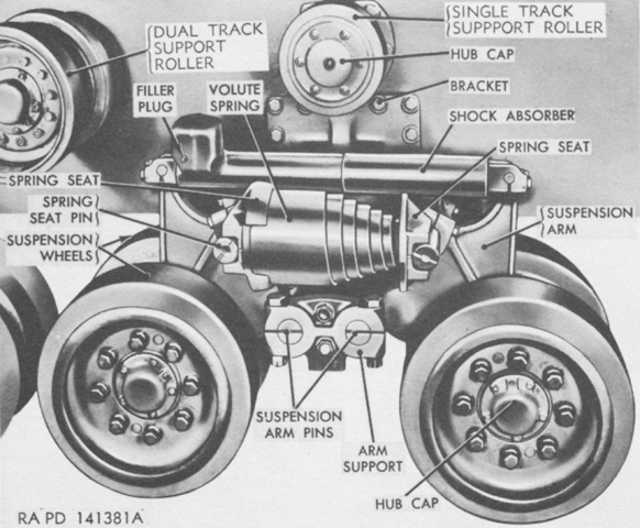
This image provides a closer look at a suspension bogie. Both types of return roller can also be seen. (Picture from TM 9-7018 Medium Tank M4A3.)
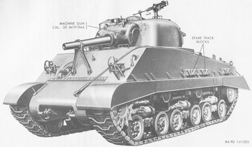
The 105mm howitzer and .50cal machine gun are both in their travel locks. (Picture from TM 9-7018 Medium Tank M4A3.)
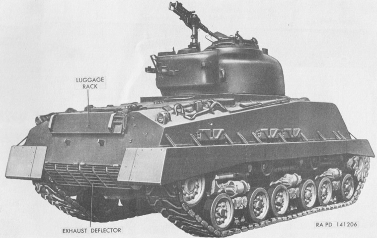
The exhaust deflector is in position, and the turret rear ventilator can be seen under the .50cal machine gun. (Picture from TM 9-7018 Medium Tank M4A3.)
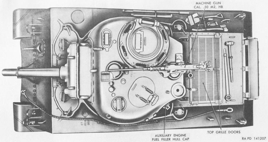
The two turret ventilators can easily be seen from above. (Picture from TM 9-7018 Medium Tank M4A3.)
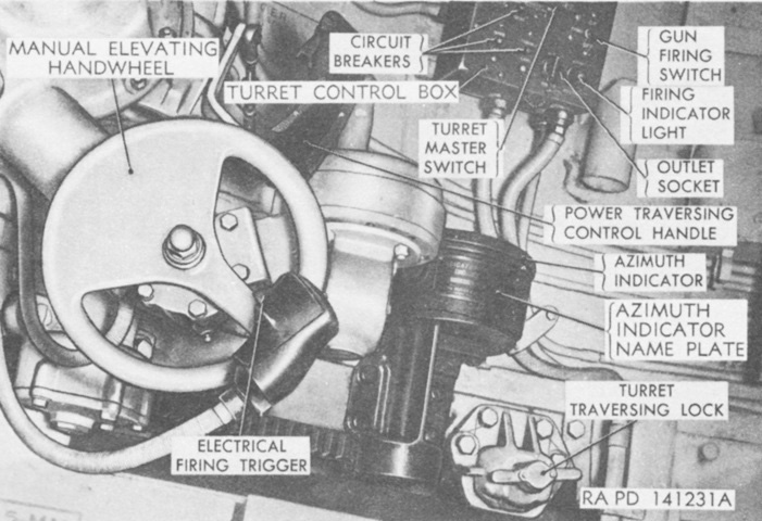
The lack of power traverse in 105mm howitzer tanks was corrected once requests from the field were received, however World War II ended before howitzer tanks fitted with power traverse could see service. (Picture from TM 9-7018 Medium Tank M4A3.)
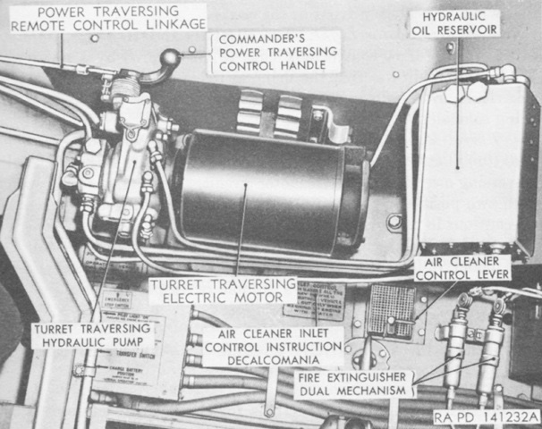
When power traverse was installed, the tank commander received a power traverse control handle as well, but the gunner was the only one with elevation controls. (Picture from TM 9-7018 Medium Tank M4A3.)
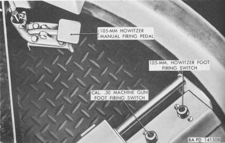
In addition to the electrical howitzer firing button on his hydraulic traversing control handle and the electrical machine gun firing button on his elevation handwheel, the gunner was provided with electrical foot triggers as well as a foot pedal to fire the howitzer manually. (Picture from TM 9-7018 Medium Tank M4A3.)
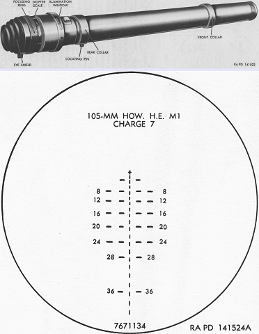
The telescope M76G was a 3x, straight tube instrument with a reticle graduated for the same shell, muzzle velocity, and jump as that found in the telescope M72D. The cross represented zero range and deflection and was used for boresighting. Each part of the broken vertical line represented 100 yards (90m) range, and were numbered in hundreds of yards. Each horizontal line and space represented 5 mils deflection. (Picture from TM 9-7018 Medium Tank M4A3.)
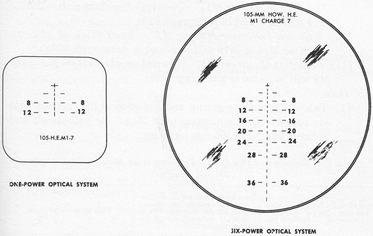
The periscopes M16D and M10D were similar to the M16F and M10C, respectively, but used reticles for the howitzer seen here. (Picture from TM 9-7018 Medium Tank M4A3.)
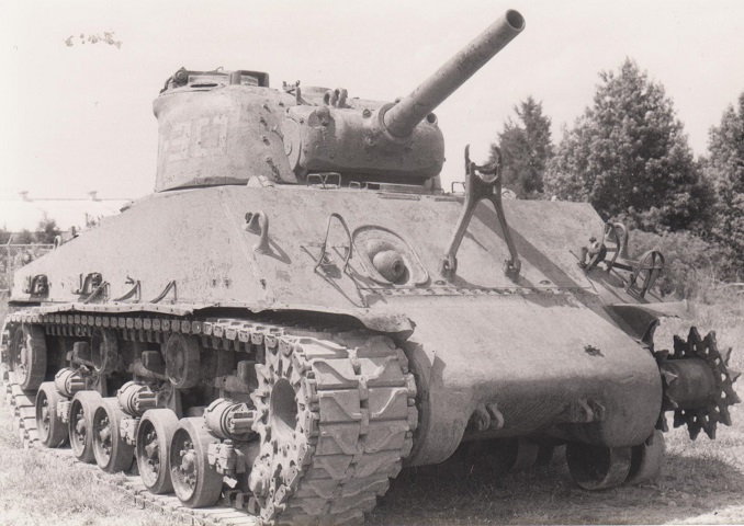
This somewhat derelict M4A3(105) HVSS Sherman features the armored cover protecting the gunner's telescope. This could be pivoted down out of the way when in action, and a path for its movement has been machined out of the howitzer shield. (Photo by Richard S. Eshleman.)
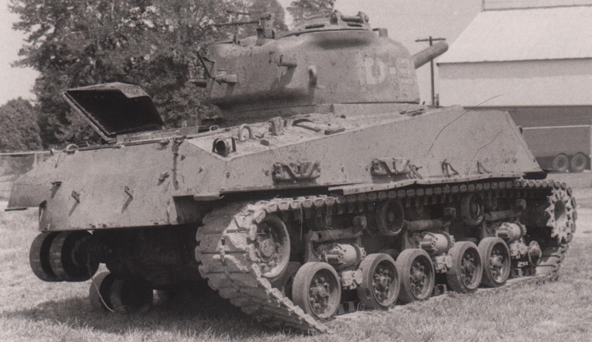
The underside of the left air intake grille can be seen from the rear, and with the missing tracks the dual nature of the road and idler wheels is visible. (Photo by Richard S. Eshleman.)
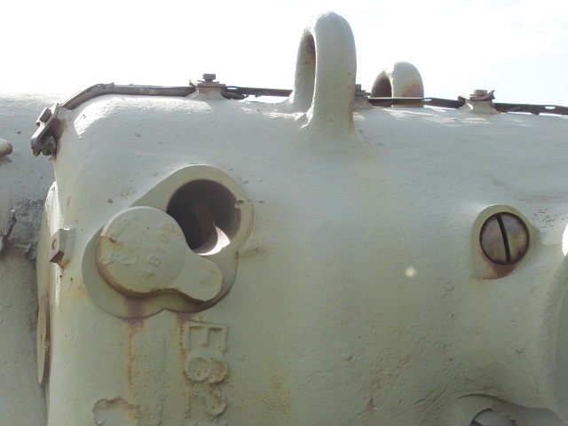
The gunner's telescope cover is rotated down on this machine.
