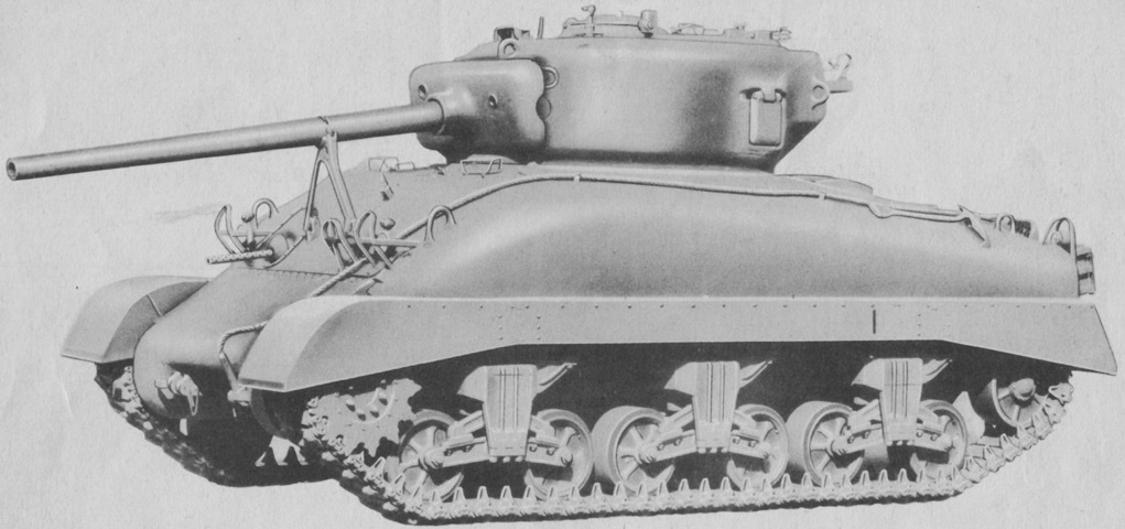
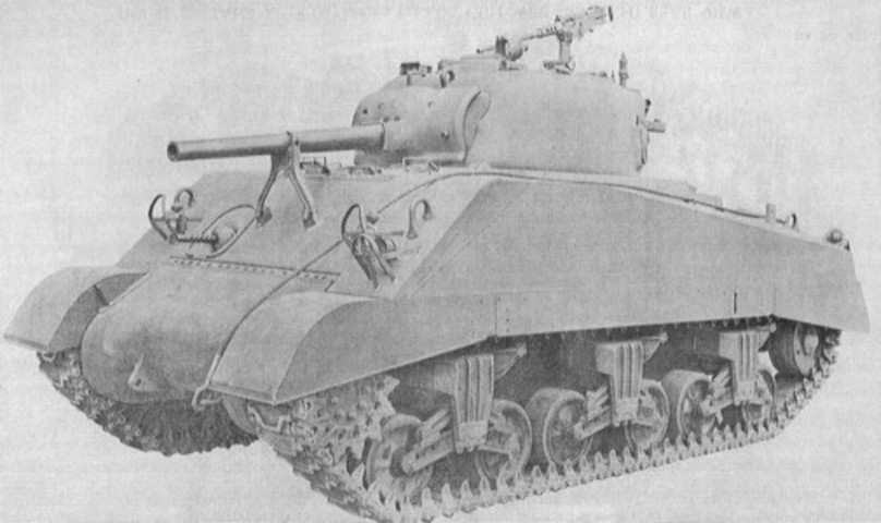
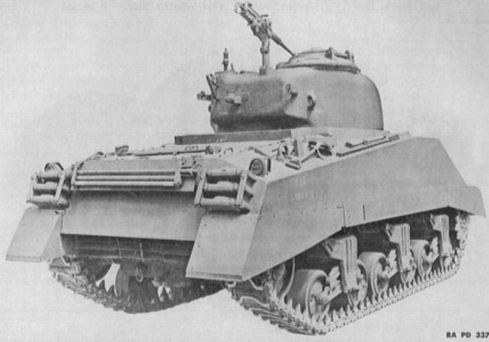
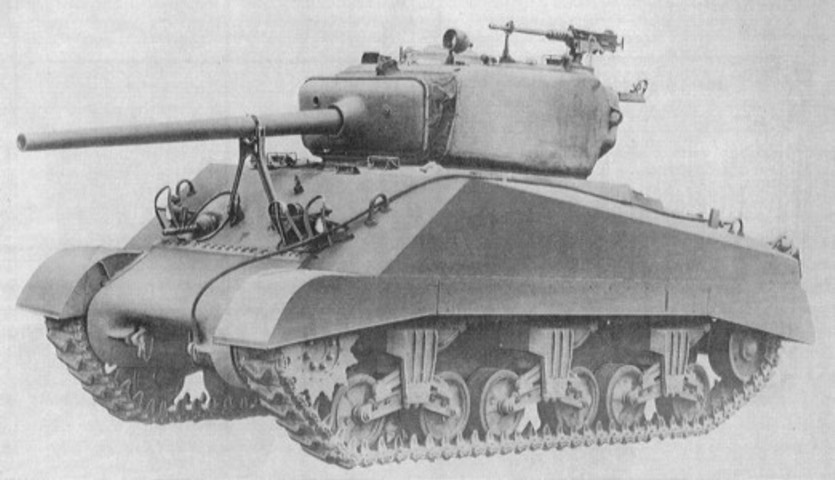
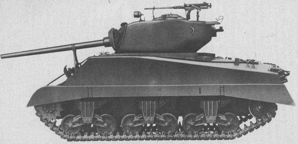
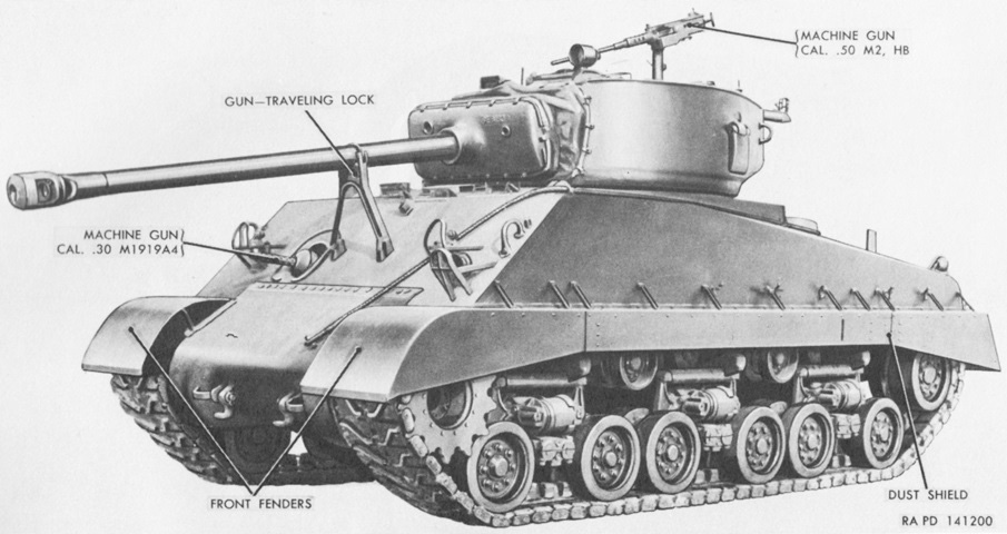
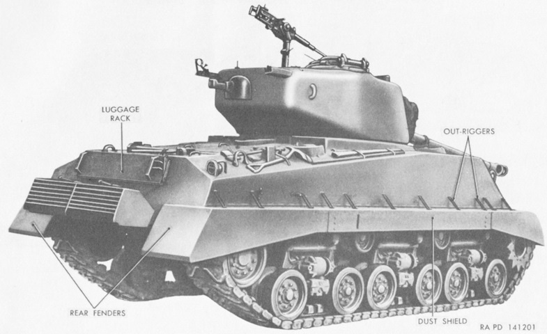
Medium Tank M4A1(76)W Sherman.
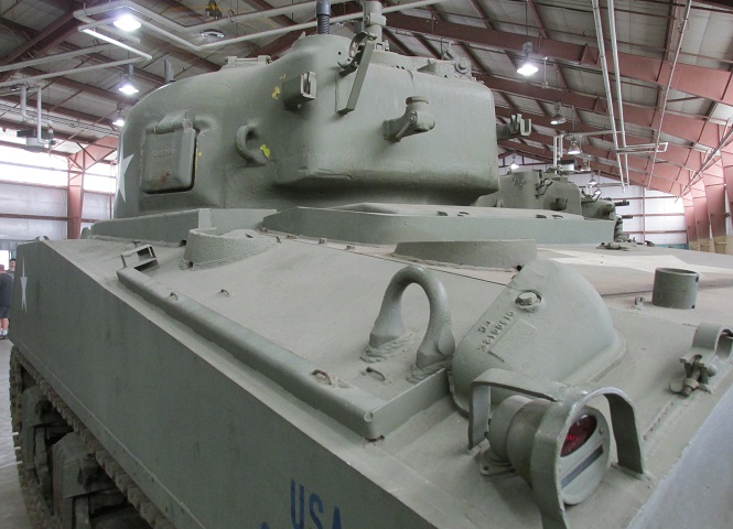
When comparing 76mm gun tanks with the 75mm gun tanks, the new turret borrowed from the medium tank T23 is an obvious difference. A new gun travel lock was also needed for the longer weapon, and it is deployed. The stowage brackets for the .50cal machine gun can be glimpsed on the turret bustle. (Picture from TM 9-731AA Medium Tank M4 (105-mm Howitzer) and Medium Tank M4A1 (76-mm Gun).)
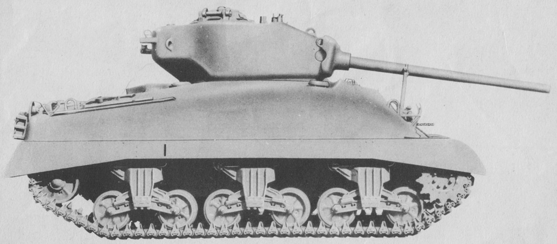
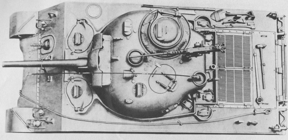
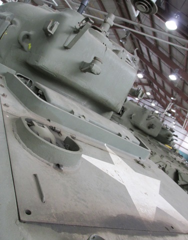
The new turret can be seen here in profile. The much longer gun tube is obvious compared to the 75mm gun M3. (Picture from TM 9-731AA Medium Tank M4 (105-mm Howitzer) and Medium Tank M4A1 (76-mm Gun).)
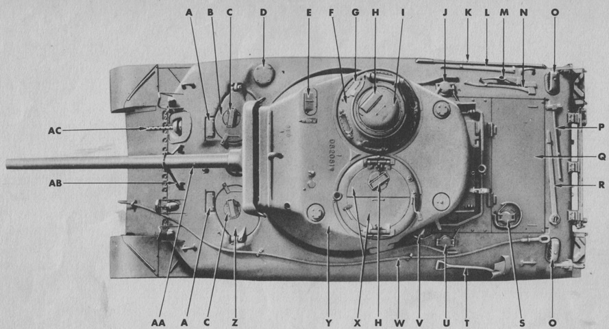
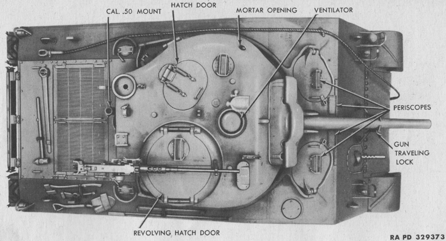
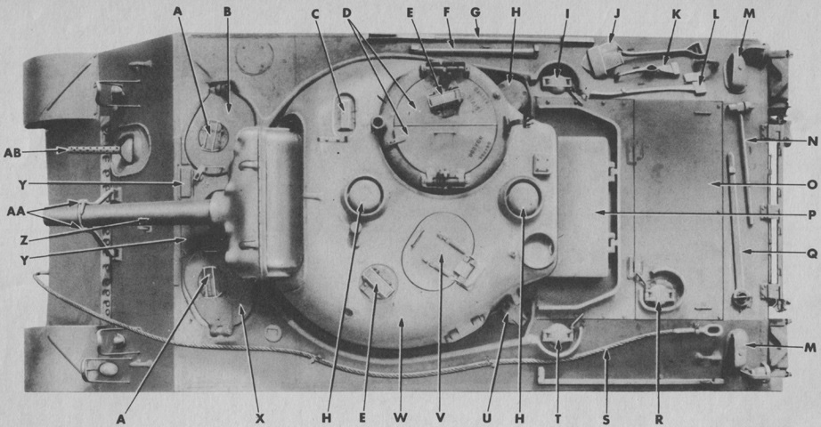
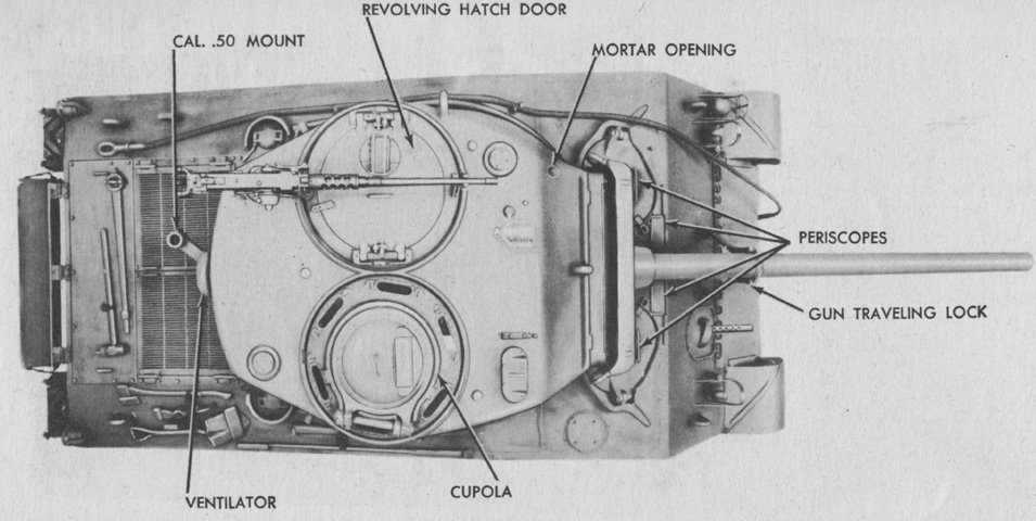
The top of a tank with a commander's vision cupola and loader's split hatch is diagrammed here. A. Periscope holder. B. Assistant driver's hatch door. C. Periscope. D. Ventilator. E. Sighting device. F. Commander's vision cupola. G. Direct vision block. H. Periscope. I. Cupola escape door. J. Right fuel tank filler cap cover. K. Crow bar. L. Mattock handle. M. Mattock. N. Ax. O. Grouser compartment scoop. P. Sledge hammer. Q. Engine compartment cover, rear. R. Track adjusting wrench. S. Engine oil tank filler cap cover. T. Shovel. U. Left fuel tank filler cap cover. V. Auxiliary generator fuel tank filler cap cover. W. Towing cable. X. Turret hatch doors. Y. Turret. Z. Driver's hatch door. AA. 76-mm gun. AB. Gun traveling lock. AC. .30 cal. gun. (Picture from TM 9-731AA Medium Tank M4 (105-mm Howitzer) and Medium Tank M4A1 (76-mm Gun).)
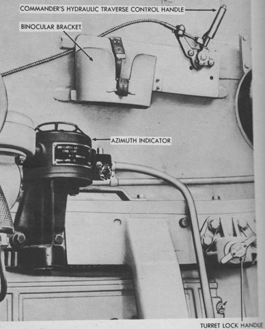
The tank commander's hydraulic traverse control handle for the Oilgear traverse system would override inputs by the gunner, allowing the commander to take control of the turret at any time. A button was pressed on top, then the handle was pushed forward to traverse counterclockwise or pulled backwards to traverse clockwise. (Picture from TM 9-731AA Medium Tank M4 (105-mm Howitzer) and Medium Tank M4A1 (76-mm Gun).)
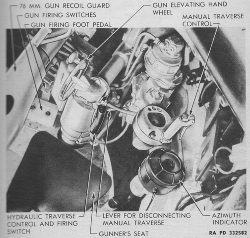
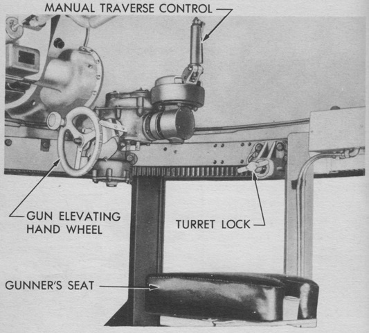
The gunner's controls are labeled in this image. (Picture from TM 9-731AA Medium Tank M4 (105-mm Howitzer) and Medium Tank M4A1 (76-mm Gun).)
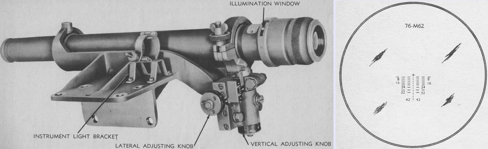
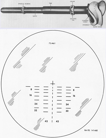
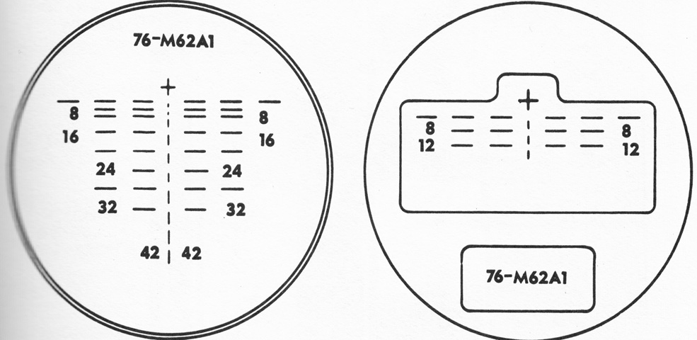
The telescope M71D is seen here installed in the telescope mount M57, which would be attached to the right side of the gun mount. The M71D was a straight, lens-erecting 5x telescope with a 13° field of view. The instrument light M33 could be secured in the bracket on the telescope mount when an illuminated reticle was necessary. The reticle for the telescope is drawn on the right. It was graduated for the armor-piercing capped projectile M62 fired with a 2,600feet/sec (790m/s) muzzle velocity and a 1.0 mil jump. The cross at the top of the reticle was used when boresighting, and the range markings below were in hundreds of yards. Each horizontal line and space represented a 5-mil deflection. (Picture from TM 9-731AA Medium Tank M4 (105-mm Howitzer) and Medium Tank M4A1 (76-mm Gun).)
The reticle of the telescope M47 in the periscope M4 is the subject of this sketch. (Picture from TM 9-731AA Medium Tank M4 (105-mm Howitzer) and Medium Tank M4A1 (76-mm Gun).)
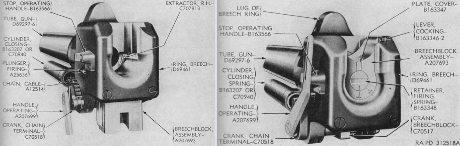
The sliding wedge breechblock of the 76mm gun is shown open on the left and closed on the right. The gun weighed 1,206lb (574.0kg) without the muzzle brake. There were 28 grooves in the bore, which were .040" (.102cm) deep and .1866" (.4740cm) wide, with the lands being .150" (.38cm) wide. (Picture from TM 9-1308 Ordnance Maintenance--76-mm Guns M1A1C and M1A2; Gun Mount M1 and Combination Gun Mount M62 for Combat Vehicles.)
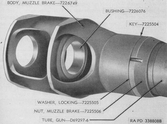
The muzzle brake M2 is seen installed on the ordnance. (Picture from TM 9-1308 Ordnance Maintenance--76-mm Guns M1A1C and M1A2; Gun Mount M1 and Combination Gun Mount M62 for Combat Vehicles.)
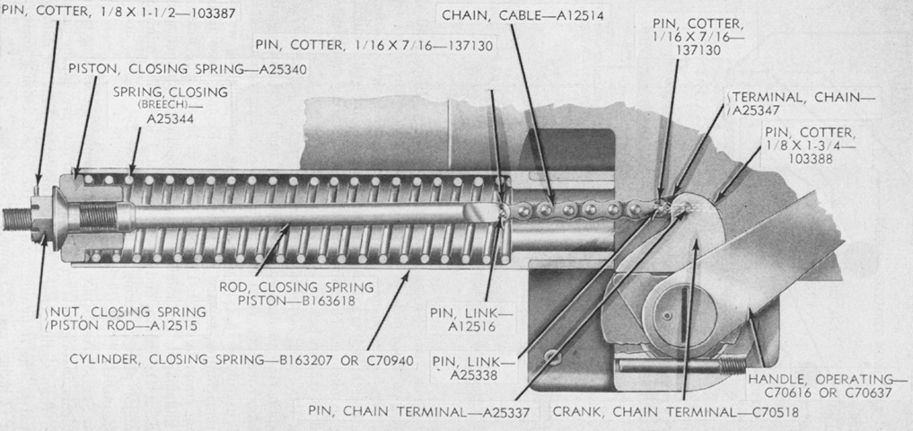
A cross-section of the 76mm gun's closing spring is drawn here. This spring worked to close the breech when a round was inserted. (Picture from TM 9-1308 Ordnance Maintenance--76-mm Guns M1A1C and M1A2; Gun Mount M1 and Combination Gun Mount M62 for Combat Vehicles.)
The 76mm gun M1A2 is installed in the combination gun mount M62, but the coaxial machine gun and recoil guard are not present. Note that the breechblock is horizontal, and closed toward the loader. (Picture from TM 9-1308 Ordnance Maintenance--76-mm Guns M1A1C and M1A2; Gun Mount M1 and Combination Gun Mount M62 for Combat Vehicles.)
The combination gun mount M62 is seen from the opposite side. (Picture from TM 9-1308 Ordnance Maintenance--76-mm Guns M1A1C and M1A2; Gun Mount M1 and Combination Gun Mount M62 for Combat Vehicles.)
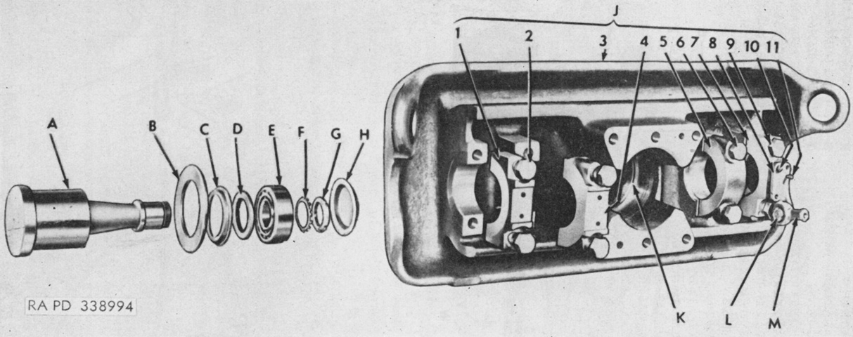
The combination gun mount M62's gun shield assembly is shown partially disassembled. A. Trunnion, gun mount. B. Spacer (trunnion). C. Retainer, oil seal. D. Seal, oil, type ML, 5.00 x 6.258 x ⅝. E. Bearing, roller. F. Washer, lock, ball bearing. G. Nut, lock, ball bearing. H. Cap, bearing closure. J. Shield, gun, assembly. 1. Cap, trunnion, left outside. 2. Screw (trunnion cap); washer, lock, 1⅛" (2.858cm). 3. Shield, gun. 4. Cap, trunnion, left inside. 5. Cap, trunnion, right inside. 6. Screw (trunnion cap); washer, lock, 1⅛" (2.858cm). 7. Cap, trunnion, right outside; pin, 0.375 x 1¼. 8. Anchor, periscope linkage. 9. Screw (trunnion cap); washer, lock, 1⅛" (2.858cm). 10. Bolt, hex-hd., ½-20NF-2 x 1⅛; washer, lock, ½" (1.3cm). 11. Pin, 0.375 x 1. K. Seal, oil, type MW, 6 29/64 x 7.256 x ¼. L. Stud, bearing; nut, lock, ball bearing; bearing, ball; washer, lock, ball bearing. M. Connector, periscope linkage; ring (connector bearing). (Picture from TM 9-1308 Ordnance Maintenance--76-mm Guns M1A1C and M1A2; Gun Mount M1 and Combination Gun Mount M62 for Combat Vehicles.)
The gun mount M62 could be found with either of two elevation mechanisms. A cross-section of elevating mechanism 7069157 is drawn here; it used shims for adjustment of the cone worm. A. Retainer, bearing. B. Shim (shifter). C. Spring (stabilizer switch arm). D. Shifter, gear left. E. Arm, stabilizer switch. F. Cover, shifter. G. Gear, spring. H. Gear, internal. J. Shifter, gear right. K. Shim (shifter). L. Box, elevating gear. M. Washer (worm gear shaft). N. Key, Woodruff, 5/32 x ⅝. P. Pinion, worm shaft. Q. Shaft, handwheel gear. R. Handwheel assembly. S. Index, handwheel, assembly. T. Housing, handwheel gear. U. Nut, safety, ⅜-24NF-3. V. Washer (worm gear shaft). W. Shim (box to housing). X. Bearing, ball. Y. Shaft, worm gear. Z. Bearing, roller. AA. Spacer, worm. BB. Shim (cone worm). CC. Worm, cone. DD. Key, square, 3/16 sq. x 2. EE. Bearing, roller. FF. Shim (retainer to bearing). (Picture from TM 9-1308 Ordnance Maintenance--76-mm Guns M1A1C and M1A2; Gun Mount M1 and Combination Gun Mount M62 for Combat Vehicles.)
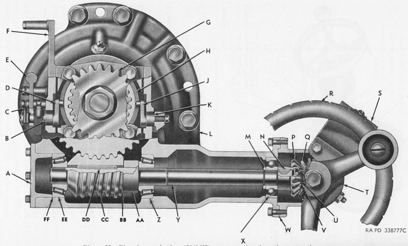
The elevating mechanism E9897, on the other hand, used an adjusting nut on the cone worm. A. Screw, set (shaft adapter). B. Fitting, lubricating, ⅛-27NPT, male. C. Shaft, handwheel gear. D. Bearing, ball. E. Index, handwheel, assembly. 1. Screw, rd-hd., no. 10-32NF-2 x ½. 2. Pointer, index. 3. Bracket, index. 4. Nut, safety, no. 10-32NF-2. F. Seal, oil, type ML, ¾ x 1.254 x ⅜. G. Washer, plate, ½" (1.3cm). H. Nut, safety, ½-20NF-3. J. Handwheel, assembly. 1. Body, handwheel. 2. Knob, handwheel. 3. Shaft, handwheel. K. Screw (bearing retainer); screw, cap, ¼-28NF02. L. Washer, lock ¼" (.64cm). M. Retainer, bearing. N. Shim (retainer to handwheel gear housing). P. Key, square 3/16 sq. x ⅝. Q. Bearing, ball. R. Shim (box to housing). S. Washer (worm gear shaft). T. Bearing, ball. U. Washer (worm gear shaft). V. Fitting, lubricating, ⅛-27NPT, male. W. Screw, cap, ½-20NF02 x 1¼. X. Washer, lock, ½" (1.3cm). Y. Key, Woodruff, 5/32 x ⅝. Z. Key, square, 3/16 sq. x 2. AA. Seal, oil, type ML, ⅞ x 1.756 x 7/16. BB. Bearing, roller. CC. Nut, adjusting. DD. Bearing, roller. EE. Screw, cap, ¼-28NF-2 x ¾. FF. Washer, lock, ¼" (.64cm). GG. Retainer, bearing; shim (retainer to bearing). HH. Worm, cone. JJ. Screw (adjusting nut). KK. Pad (adjusting nut). LL. Shaft, worm gear. MM. Box, elevating gear. NN. Dowel (elevating mechanism assembly). PP. Screw, cap, ¼-28NF-2 x ¾; screw (handwheel gear housing). QQ. Washer, lock, ¼" (.64cm). RR. Pinion, worm shaft. SS. Nut, safety, ⅜-24NF-3. TT. Housing, handwheel gear. UU. Adapter, flexible shaft. (Picture from TM 9-1308 Ordnance Maintenance--76-mm Guns M1A1C and M1A2; Gun Mount M1 and Combination Gun Mount M62 for Combat Vehicles.)
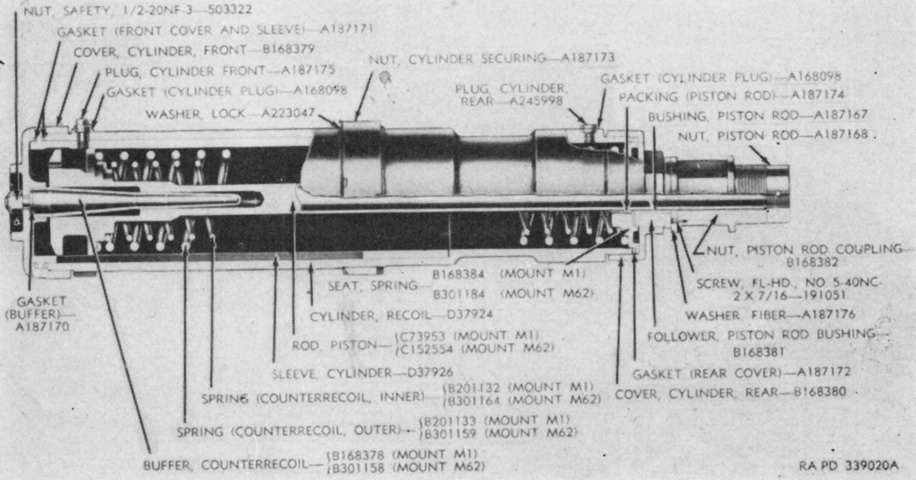
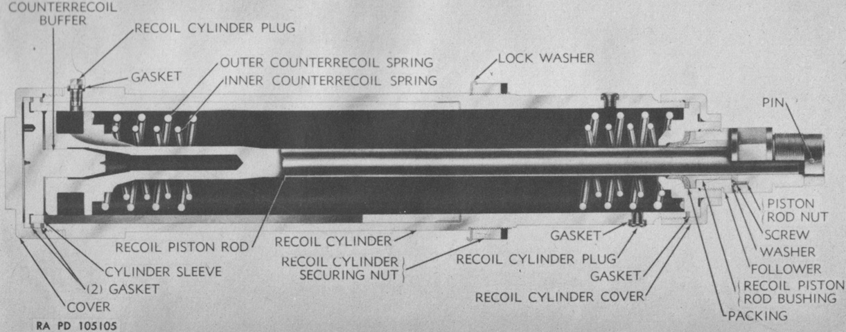
A cross-section of a recoil cylinder assembly is drawn here. The recoil mechanism D82250 used in the combination gun mount M62 was similar to the recoil mechanism D37925 found in the gun mount M1 of the 76mm GMC M18, and both are detailed in the image. When the gun was fired, the gun was forced backwards, pulling the recoil piston rods to the rear since these were attached to the breech ring. Oil would flow around the piston through grooves in the recoil cylinder sleeve. These throttling grooves were tapered toward the rear, which increased restriction of the oil as the gun moved backward. The rearward movement was arrested by the compression of the recoil springs and the pressure of the oil flowing around the piston head. Normal recoil was 12" (30cm), with a maximum of 14" (36cm). When the rearward motion of the gun was stopped, the now-compressed counterrecoil springs expanded, forcing the piston rod, and consequently the gun, forward. More grooves in the recoil cylinder sleeve controlled forward movement, and these were also tapered to their front ends. The buffer then entered the hole in the front of the piston rod near the end of the counterrecoil cycle, forcing out more oil and cushioning the counterrecoil movement. (Picture from TM 9-1308 Ordnance Maintenance--76-mm Guns M1A1C and M1A2; Gun Mount M1 and Combination Gun Mount M62 for Combat Vehicles.)
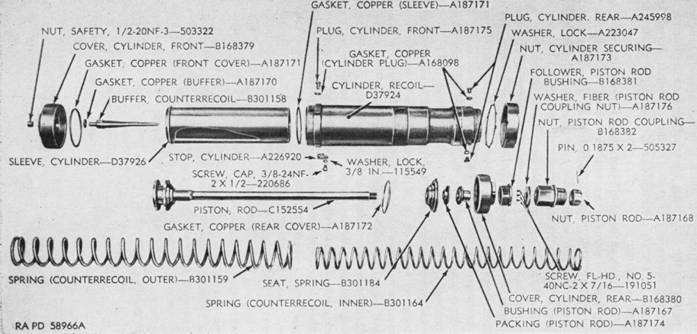
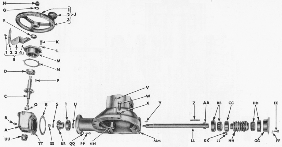
A disassembled recoil cylinder D82250 is diagrammed in this image. Two cylinders were employed on the combination gun mount M62, and each one held ~8 pints (~3.8L) of oil. The inner spring was ~31¼" (~79.38cm) in free length, and at an assembled height of 20¾" (52.71cm) its load specification was 190-220lb (96-100kg). The outer spring was ~29¾" (~75.57cm) in free length, and its load specification was 400-450lb (180-200kg) at an assembled height of 21⅜" (54.293cm). (Picture from TM 9-1308 Ordnance Maintenance--76-mm Guns M1A1C and M1A2; Gun Mount M1 and Combination Gun Mount M62 for Combat Vehicles.)
The drivers' controls are labeled in this image. (Picture from TM 9-731AA Medium Tank M4 (105-mm Howitzer) and Medium Tank M4A1 (76-mm Gun).)
The late-production instrument panel without the fire signal light is shown. A. Utility outlet socket. B. Panel light switch. C. Ammeter. D. Panel attaching screw. E. Panel light cover. F. Circuit breakers. G. Fuel gage. H. Main light switch I. Fuel gage selector switch. J. Cranking motor and magneto switch. K. Tachometer. L. Engine oil temperature gage. M. Fuel cut-off switch. N. Oil pressure gage. O. Speedometer. P. Low oil pressure warning light. (Picture from TM 9-731AA Medium Tank M4 (105-mm Howitzer) and Medium Tank M4A1 (76-mm Gun).)
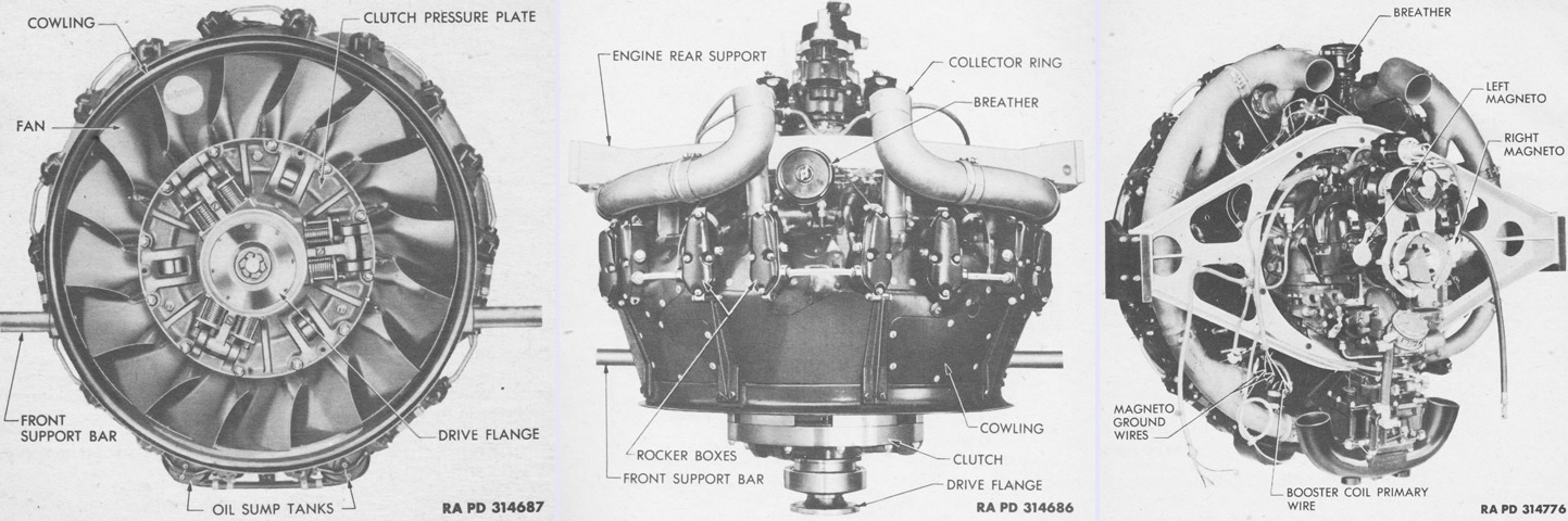
The R975 C4 engine is seen from the front, top, and left rear, respectively. The flywheel end of the engine was considered the front, and the accessory end the rear. Left and right were determined by looking at the engine from the rear. Its dry weight was 750lb (340kg). (Picture from TM 9-1725 Ordnance Maintenance--Ordnance Engine Model R975-C4 (Continental).)
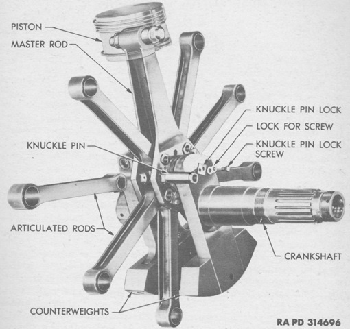
The crankshaft, connecting rods, piston, and knuckle pin assembly is assembled outside of the engine. The pistons were forged aluminum alloy full-trunk types which were numbered clockwise with the top piston being number 1. The master rod was connected to piston 1 and the crankshaft crankpin, while the other pistons were attached to articulated or connecting rods. The crankshaft was a two-piece assembly with counterweights; the rear section's counterweight was attached with loose-fitting pins, which allowed it to act as a dynamic damper to minimize crankshaft vibration. (Picture from TM 9-1725 Ordnance Maintenance--Ordnance Engine Model R975-C4 (Continental).)
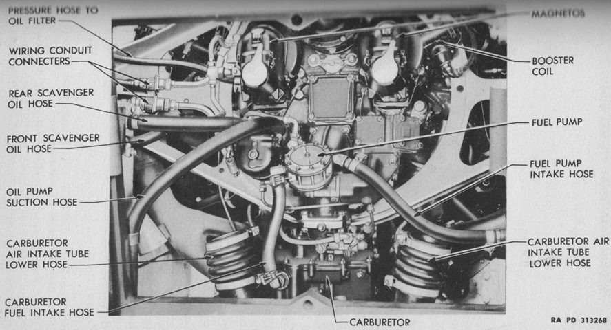
The engine is shown here through the rear hull doors, with the intake tubes removed for clarity. (Picture from TM 9-731AA Medium Tank M4 (105-mm Howitzer) and Medium Tank M4A1 (76-mm Gun).)
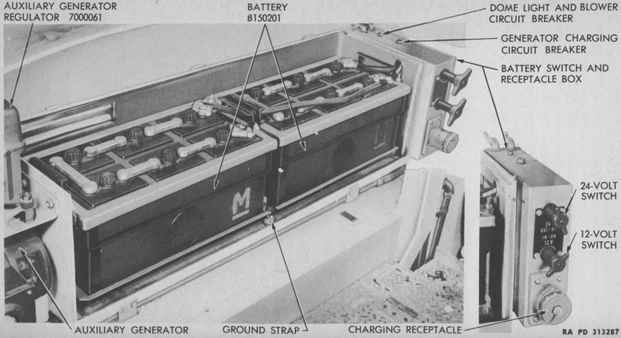
With ammunition stowage being moved to the floor, the batteries were instead installed in a box in the left sponson, which is seen here with its cover removed. The two 12-volt batteries were connected in series to the 24-volt switch on the battery switch box, and a separate lead from one battery supplied voltage to the 12-volt switch for the radio circuit. (Picture from TM 9-731AA Medium Tank M4 (105-mm Howitzer) and Medium Tank M4A1 (76-mm Gun).)
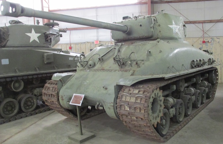
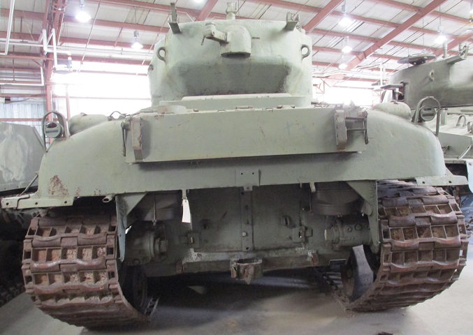
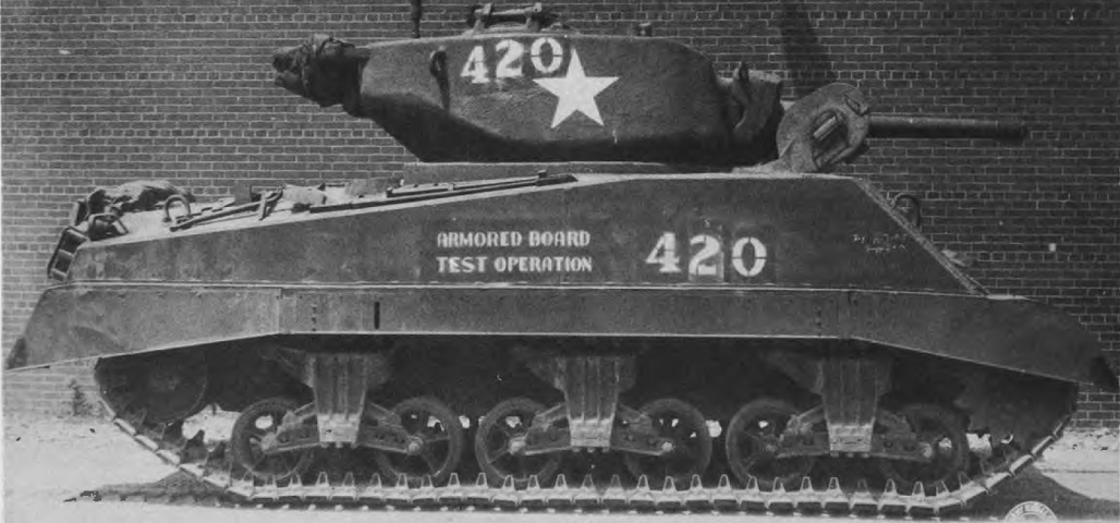
This is one of the 1465 M4A1(76)Ws fitted with horizontal volute spring suspension, and it is wearing single-pin steel T66 tracks. Spare track shoes are stowed on the fenders. The shock absorbers are mounted above the bogies horizontally.
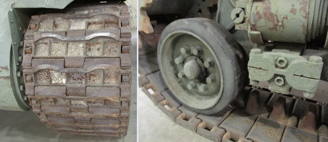
Further details of the T66 track are shown here. Single-pin track was relatively rare on American tanks at this time. As seen on the right, the rear face of the track was steel as well, which was more wearing on suspension components versus rubber or rubber-backed track. The horizontal volute spring of the forward bogie is visible in this image.
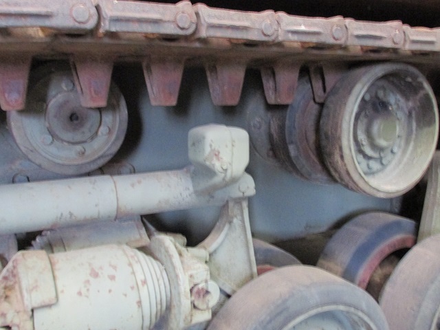
Both types of return roller can be seen in this picture. There were three of the single rollers supporting only the inner run of the track at the front, center, and rear of the hull, and dual return rollers were placed between the single models.
The procedure for adjusting the track tension with HVSS was the same for VVSS, as described above.
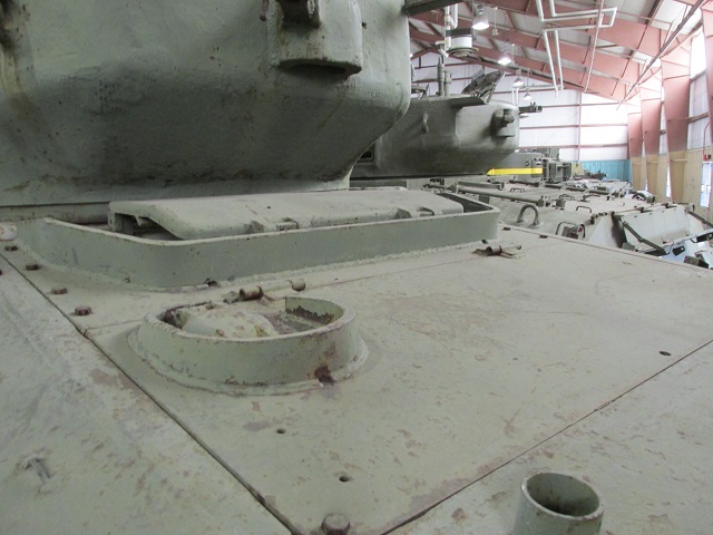
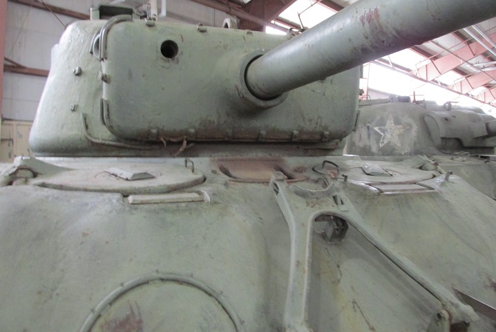
A filler cap for lubricating oil was added in the rear deck plate on later-production radial-engined tanks. The cylindrical socket for holding the idler wheel adjusting wrench has been moved to the top of the rear deck and can be seen at the bottom of the picture. The turret on this tank is equipped with a ventilator at the rear, and its armored exhaust port can be seen on the turret bustle; the stowage pintle for the .50cal machine gun is welded to this port. Early 76mm gun turrets did not feature this ventilator since the medium tank T23 for which the turret was designed had a stronger ventilator between the drivers.
The drivers' larger hatches and the two periscopes for each man can be seen in this image. A ventilator was mounted between them; a cover for the ventilator was not present on early vehicles.
The shallow horseshoe shape originally found in the rear armor eventually was leveled out to improve protection for the air cleaners; triangular armor pieces were also added at the upper corners. The turret ventilator can better be seen in this image, as well as the .50cal MG stowage brackets. The top portion of the MG mounting post is visible on the turret roof.
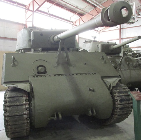
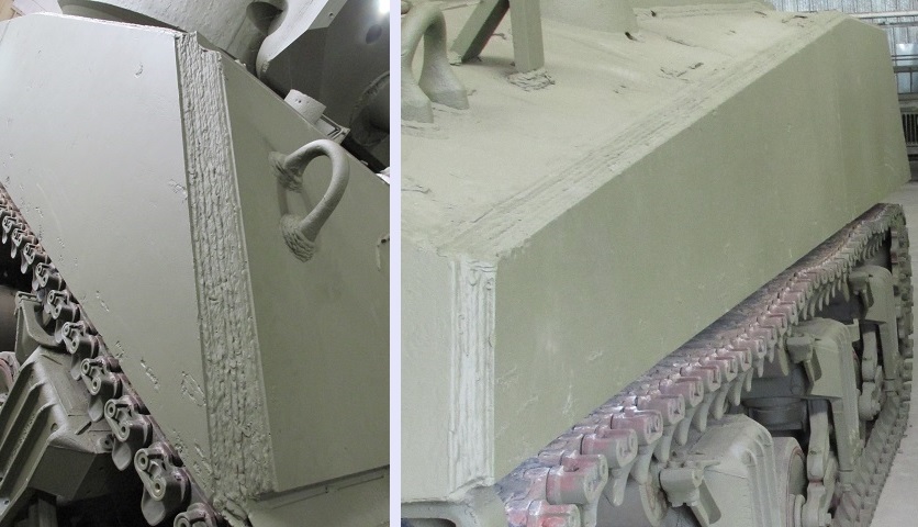
The contours of the welded and cast hull tanks can be easily contrasted in this picture.
The longer final drive covers for tanks with HVSS can be contrasted to the shorter cover on the removed transmission and final drive assembly above. (Picture from ORD 9 SNL G-207.)
The wet ammunition stowage rendered the applique armor applied over the ammunition racks of earlier tanks redundant. The second set of drivers' periscopes that replaced the earlier direct vision slots are also visible from this angle. (Picture from ORD 9 SNL G-104, Vol. 15.)
Stowage on the rear of the tank includes track shoes on each side of the hull and gun cleaning equipment on the underside of the crew's blanket rack. The turret rear can also be contrasted with that of earlier 75mm gun tanks. The larger hatches built into the 47° glacis tanks required raising the turret bustle a few inches to allow for clearance. This can be seen here along with the less severe slope of the top of the turret bustle, especially when the antenna mounts are compared. (Picture from ORD 9 SNL G-104, Vol. 15.)
The 47° glacis plate, larger drivers' hatches, and higher-bustle turret are all illustrated from this angle. (Picture from TM 9-759 Tank, Medium, M4A3.)
The commander's vision cupola has replaced his split hatch on this tank, and the .50cal machine gun is mounted on the rooftop pintle. Compared to the split hatch, the cupola offered increased vision at the expense of ease of use for the machine gun. The opening for the 2" smoke mortar has been plugged, and a radio antenna is present in the turret bustle mount. (Picture from TM 9-7018 Medium Tank M4A3.)
The turret rear stowage points for the .50cal machine gun are labeled here. (Picture from TM 9-7018 Medium Tank M4A3.)
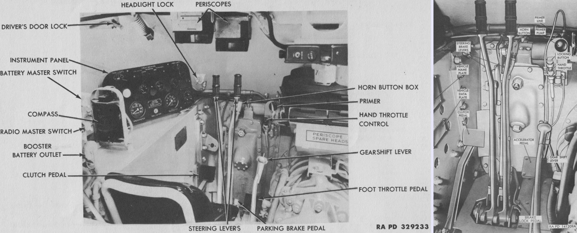
The late-production driver's position is shown in these images, with a broader view on the left and the controls isolated on the right. (Picture from TM 9-759 Tank, Medium, M4A3 and TM 9-7018 Medium Tank M4A3.)
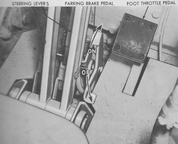
The later-production parking brake control is highlighted here. Early tanks had a transmission-mounted parking brake, but this was replaced by pawl acting on the steering levers that was set and released via a foot pedal. (Picture from TM 9-759 Tank, Medium, M4A3.)
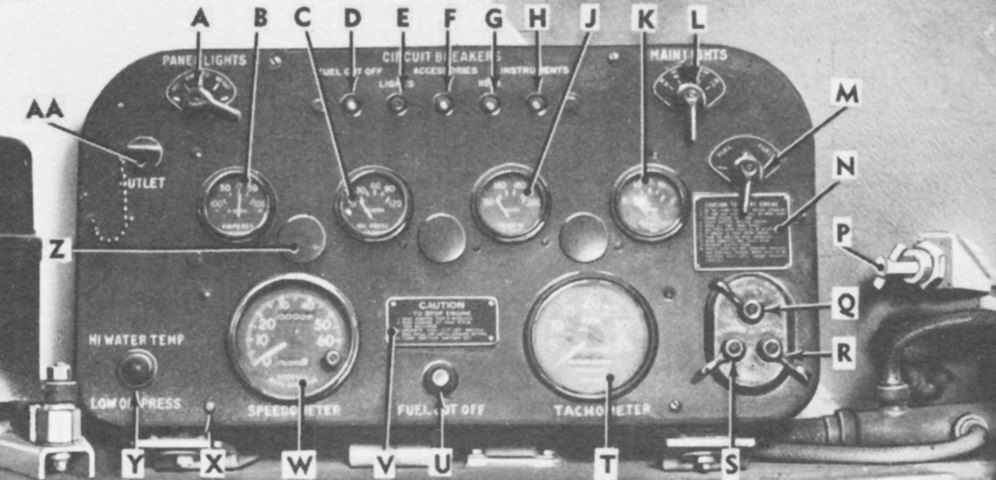
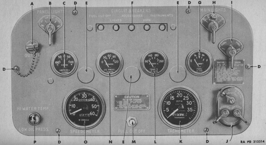
The late-production driver's instrument panel is labeled here. A. Panel light switch. B. Ammeter. C. Oil pressure gage. D. Fuel cut-off circuit breaker. E. Vehicle lights circuit breaker. F. Accessory equipment circuit breaker. G. Horn circuit breaker. H. Instrument panel circuit breaker. J. Engine water temperature gage. K. Fuel gage. L. Main light switch. M. Fuel tank selector switch. N. Engine start caution plate. P. Head light lock. Q. Ignition switch. R. Starter switch. S. Booster switch (not used). T. Tachometer. U. Fuel cut-off switch. V. Engine stop caution plate. W. Speedometer. X. Instrument panel mounting cap screw. Y. High water temperature and low-oil-pressure warning light. Z. Panel light covers. AA. Utility outlet. (Picture from TM 9-7018 Medium Tank M4A3.)
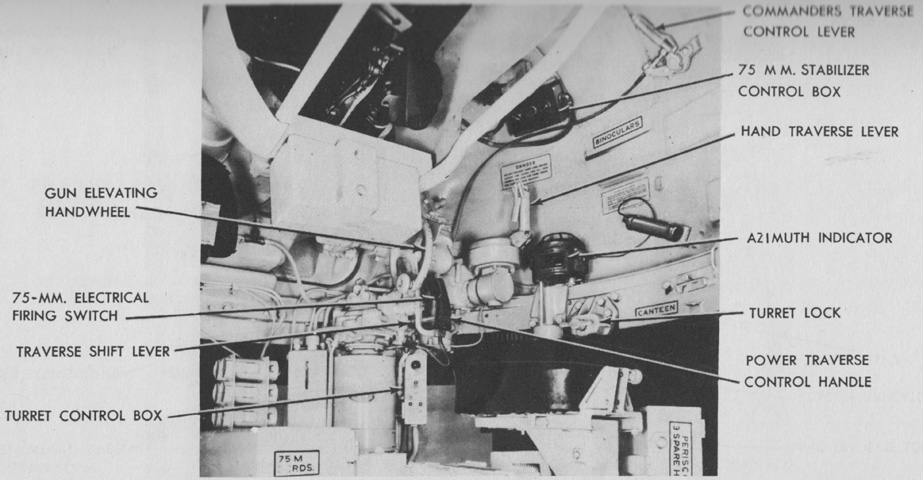
The gunner's controls are shown in this picture, and the box of 75mm ready rounds is labeled on the floor. (Picture from TM 9-759 Tank, Medium, M4A3 and TM 9-7018 Medium Tank M4A3.)
The telescope M70F was a 3x, erect-image type with a field of view of 12°19'. It was 22½" (57.2cm) long. The reticle pattern was graduated for the armor-piercing capped M61 projectile with a 2,030 ft/sec (619m/s) muzzle velocity and a 0.3-mil jump. The center of the cross represented zero range or deflection, and was used when boresighting. Each vertical line and space represented 200 yards (180m) range, while each horizontal line and space represented 5 mils deflection. (Picture from TM 9-7018 Medium Tank M4A3.)
The periscope M4A1 with telescope M38A2 was similar to the periscope M4 with telescope M38 except that provision for an instrument light was added, and the reticle was changed to the one found on the telescope M70F. (Picture from TM 9-7018 Medium Tank M4A3.)
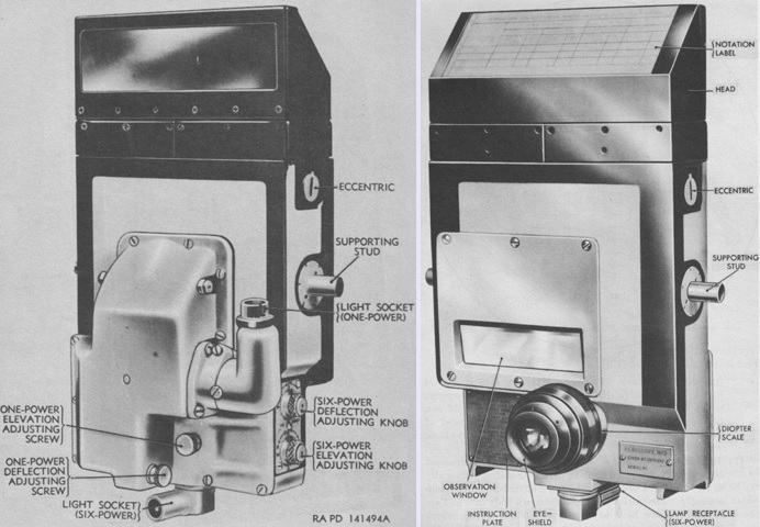
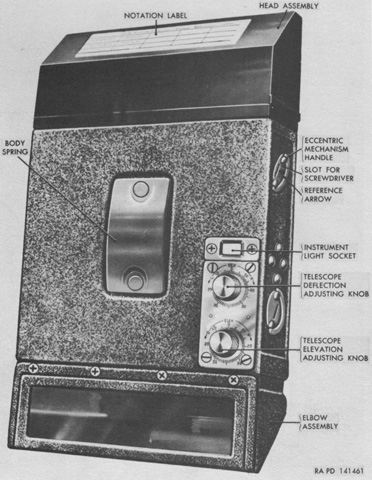
The periscope M10C contained both 1x and 6x optical systems. The 1x system had a horizontal field of view of 42°10', and a vertical field of view of 8°10', while the 6x field of view was 11°20'. (Picture from TM 9-7018 Medium Tank M4A3.)
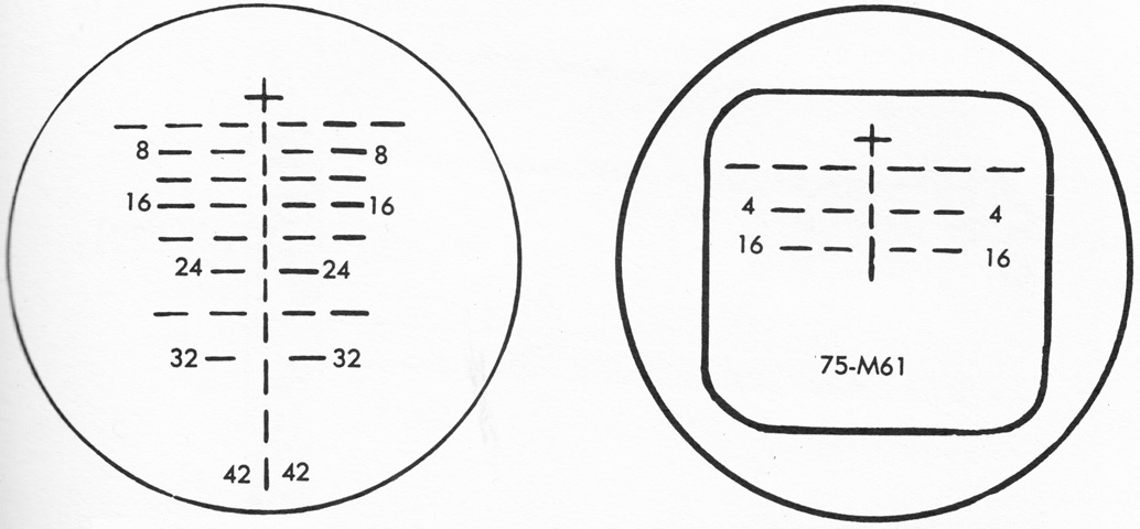
The reticle pattern for the 6x system of the periscope M10C, similar to that found in the telescope M70F, is drawn on the left, with the 1x reticle on the right. (Picture from TM 9-7018 Medium Tank M4A3.)
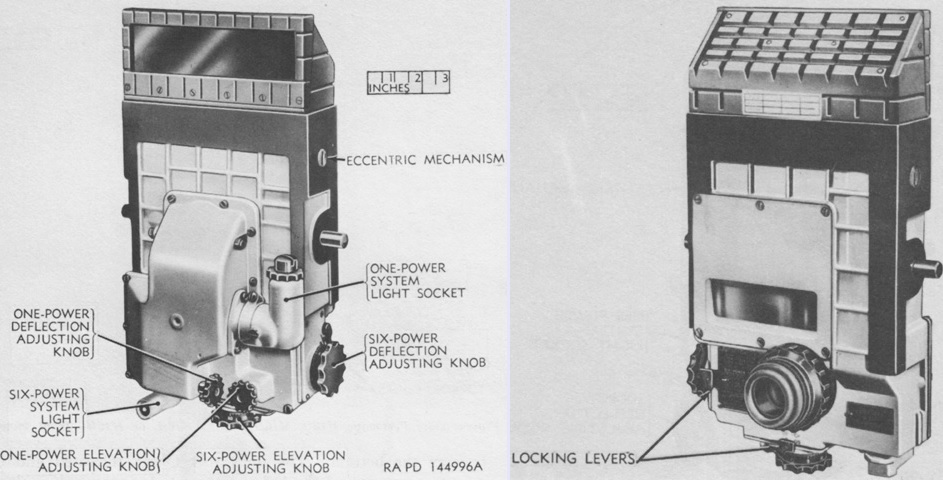
The periscope M16F replaced the M10C, and also contained both a unity and a 6x optical system. The 6x elevation and deflection adjusting knobs were enlarged and provided with positive action locking levers to prevent accidental turning. The knobs were located on the left side and the bottom of the periscope. Scales graduated in ~½-mil increments were used to register boresight adjustments. The light socket was also moved, and light transmission to the reticle was via a plastic rod. The reticles were the same as those in the periscope M10C. (Picture from TM 9-7018 Medium Tank M4A3.)
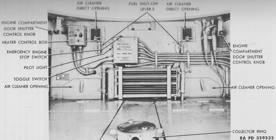
Fixtures on the engine bulkhead are labeled; the floor ammunition bins can be seen in the foreground. (Picture from TM 9-759 Tank, Medium, M4A3.)
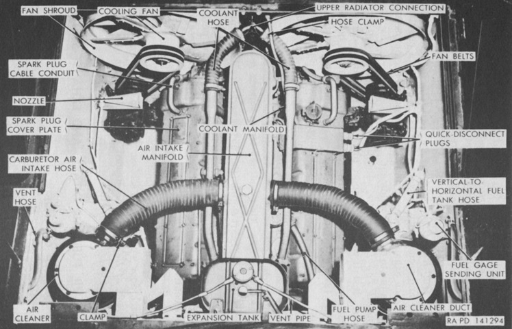
The engine is installed in the vehicle in this image. The front of the tank is to the bottom of the picture. Early tanks had the air cleaners mounted on the fighting compartment side of the engine firewall. (Picture from TM 9-7018 Medium Tank M4A3.)
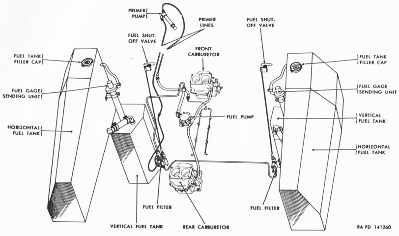
In late-production tanks, the fuel system was changed to incorporate a second fuel filter, while the shutoff valves were reduced to two in number. (Picture from TM 9-7018 Medium Tank M4A3.)
With the advent of wet ammunition stowage in the hull floor, the batteries were moved to the left sponson. A single generator and generator regulator was used instead of the pair of each in earlier tanks. (Picture from TM 9-7018 Medium Tank M4A3.)
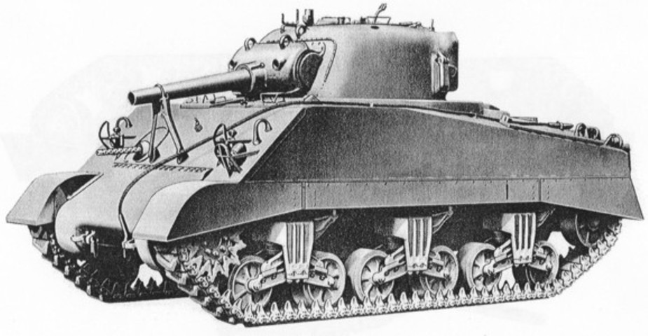
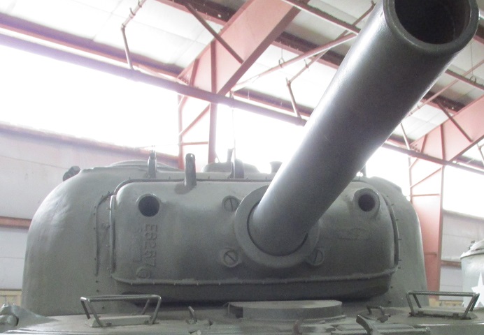
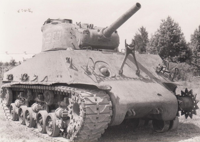
The shorter, thicker barrel on this tank's ordnance, the lifting eyes on the upper lip of the ordnance shield, the large screws evenly spaced around the ordnance, and the location of the travel lock indicate that it is a 105mm howitzer tank. (Picture from ORD 9 SNL G-104, Vol. 6, 11, and 14.)
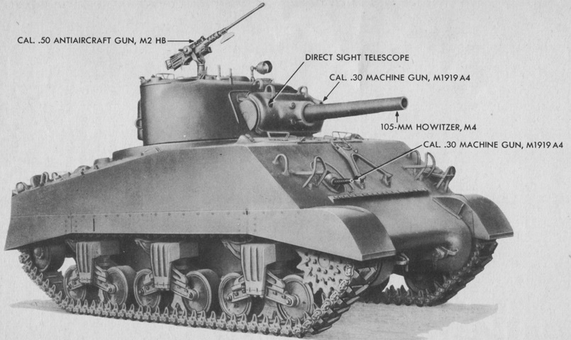
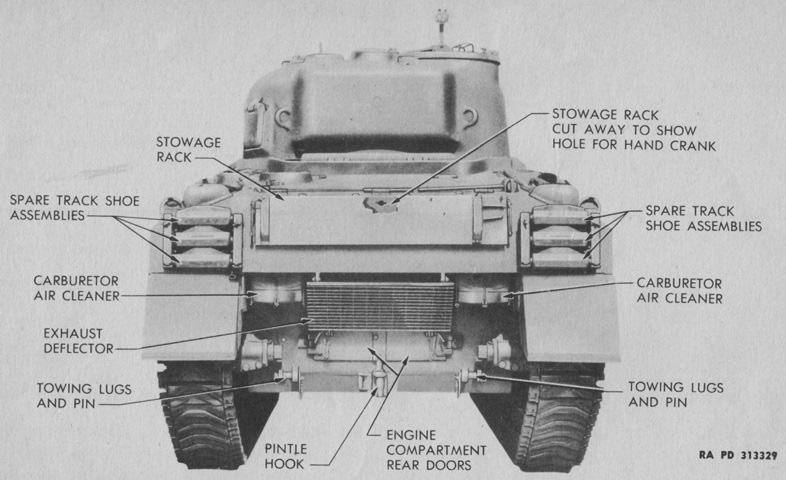
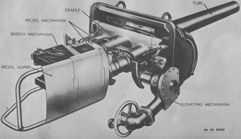
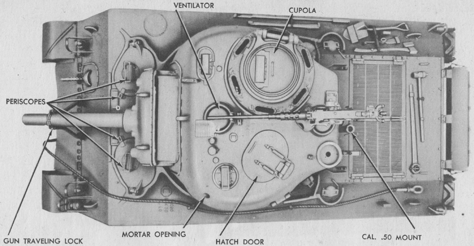
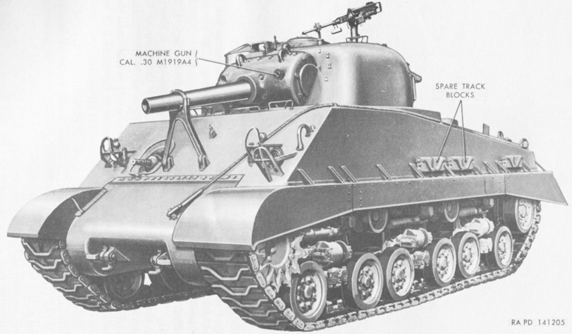
The weapons of a 105mm howitzer tank are labeled. (Picture from TM 9-731AA Medium Tank M4 (105-mm Howitzer) and Medium Tank M4A1 (76-mm Gun).)
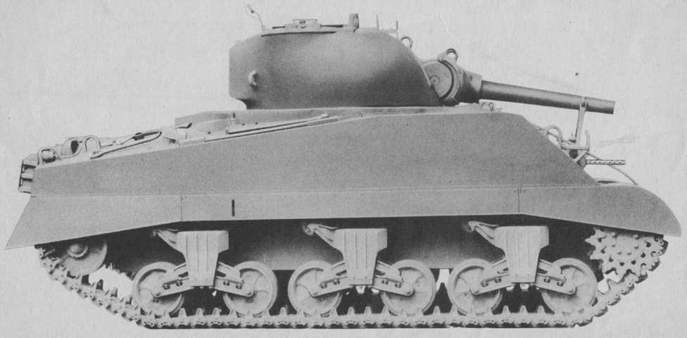
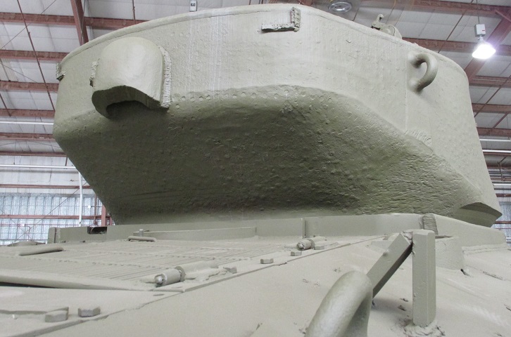
Compared to 75mm gun tanks, the 105mm howitzer shield was thicker and protruded a larger distance from the turret front. The turret itself was similar to the 75mm gun turret found on tanks with the 47° glacis. (Picture from TM 9-731AA Medium Tank M4 (105-mm Howitzer) and Medium Tank M4A1 (76-mm Gun).)
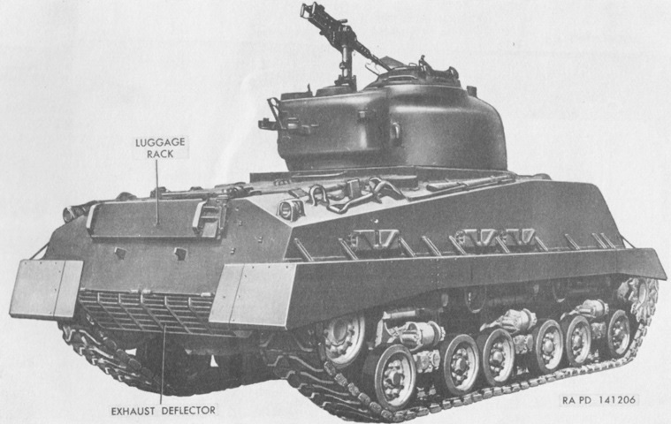
From behind, the second turret ventilator is visible adjacent to the commander's position. (Picture from TM 9-731AA Medium Tank M4 (105-mm Howitzer) and Medium Tank M4A1 (76-mm Gun).)
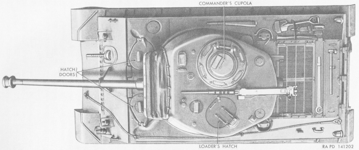
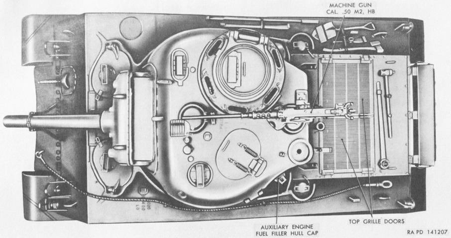
The top of the tank is shown here. A. Periscope. B. Assistant driver's hatch door. C. Sighting device. D. Turret hatch doors. E. Periscope. F. Mattock handle. G. Crowbar. H. Ventilator. I. Right fuel tank filler cap cover. J. Shovel. K. Mattock. L. Ax. M. Grouser compartment scoop. N. Sledge hammer. O. Engine compartment cover, rear. P. Engine compartment air inlet grille cover. Q. Track adjusting wrench. R. Engine oil tank filler cap cover. S. Towing cable. T. Left fuel tank filler cap cover. U. Auxiliary generator fuel tank filler cap cover. V. Loader's escape hatch. W. Turret. X. Driver's hatch door. Y. Periscope holder. Z. 105-mm gun. AA. Gun traveling lock. AB. .30 cal. gun. (Picture from TM 9-731AA Medium Tank M4 (105-mm Howitzer) and Medium Tank M4A1 (76-mm Gun).)
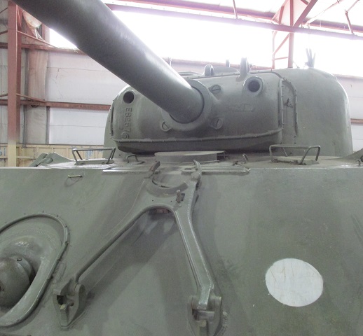
The howitzer travel lock is mounted lower on the upper hull front plate than that for the 75mm gun, which can be easily seen when its location vis-à-vis the bow machine gun is compared with the gun travel lock of the 75mm gun tank above. An attachment for a dust cover can be seen ringing the howitzer shield and the turret front. The howitzer shield features lifting hooks at the top and large screws at the base of the ordnance. The drivers' hatches with their periscopes can be seen, and their increased width compared to earlier vehicles made exiting easier. The hull ventilator between the drivers is fitted with a cover.
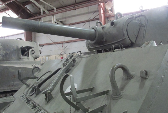
The tall hinge associated with the large drivers' hatches is apparent at the driver's station; the turret bustle was raised in order to clear these hinges. Note the double-ended bolts in the final drive and differential housing in front of the howitzer travel lock; these were part of the equipment to attach the tank mounting bulldozer M1.
The large aperture in the howitzer shield's right side was for the gunner's sighting telescope, while the opening in the left of the shield was for the coaxial .30cal machine gun.
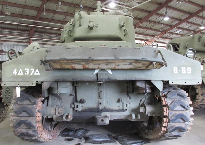
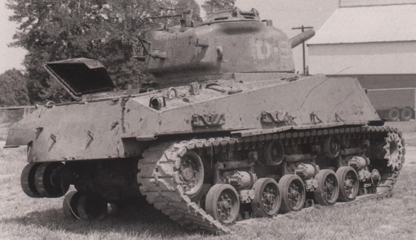
The rear hull plate has been extended to eliminate the shallow horseshoe shape in order to further protect the engine air cleaners, and supplementary armor has been installed around the air cleaners. The exhaust pipe for the auxiliary generator engine can be seen just outboard of the left air cleaner armor. A difference in howitzer turrets versus 75mm gun turrets was an additional ventilator at the rear, the opening for which can be seen between the commander's cupola and the antenna mount. The base of the .50cal machine gun mounting post was therefore designed to fit over top of this ventilator. Note that on this tank the right-hand air scoop over the track grouser compartment is missing.
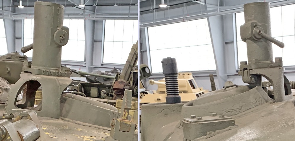
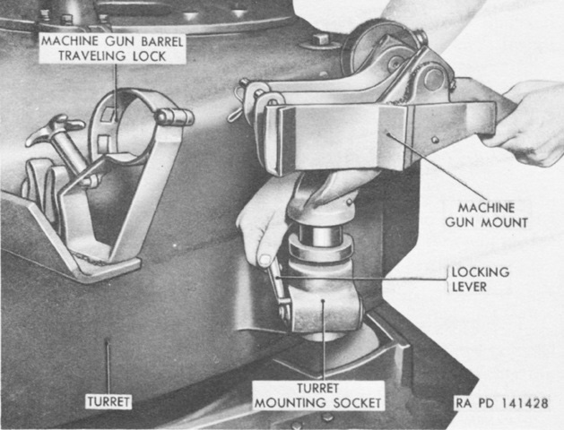
The turret roof .50 caliber machine gun mount is seen from the left front and right rear on the left and right, respectively. The post could fold to the rear when not needed, and the base that raised the mount over the turret ventilator was a three-legged affair.
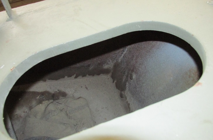
The interior of the open grouser compartment is shown here. The thickness of the hull roof armor can be seen as well.
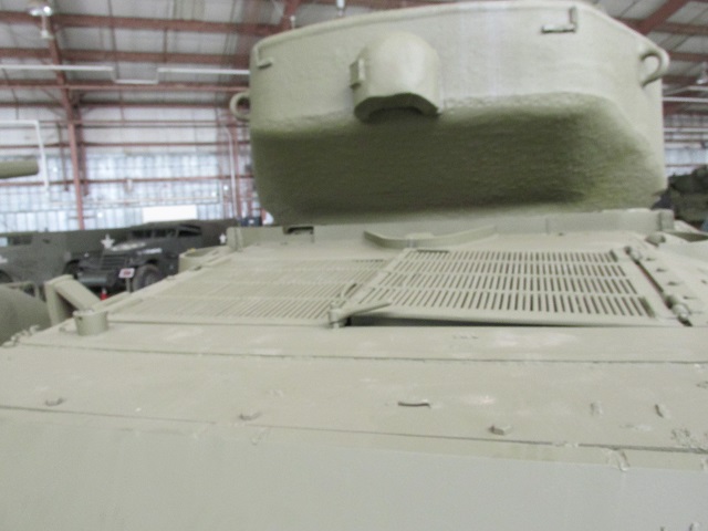
The late-production radial engine deck is illustrated here, with an additional filler cap for lubricating oil on the central deck plate. Fuel fillers are on the sloping sides on either side of the shrouded air intake, and a bracket for aiming stakes and howitzer cleaning rods is below the hull lifting eye.
The oil filler cap can be better seen from this angle, and the lip of the base of the .50cal machine gun mounting post can just be made out above the turret ventilator.
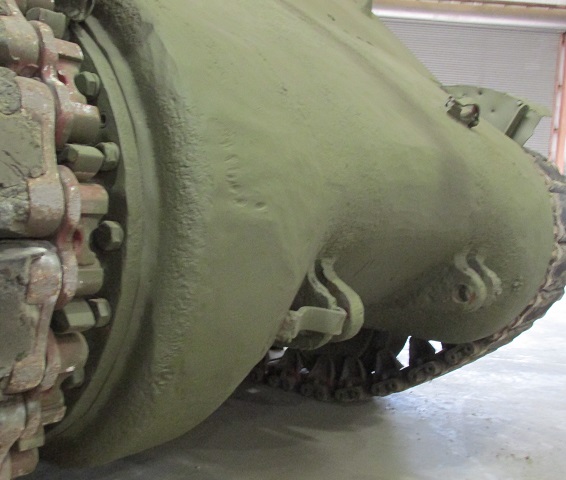
The contours of the sharp-nosed single-piece final drive and differential cover are shown here.
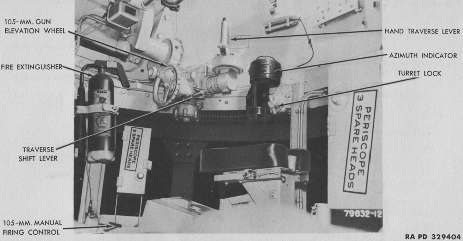
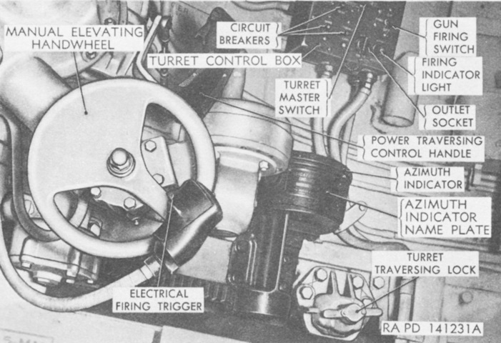
The gunner of howitzer tanks was initially provided only with manual traverse. (Picture from TM 9-731AA Medium Tank M4 (105-mm Howitzer) and Medium Tank M4A1 (76-mm Gun).)
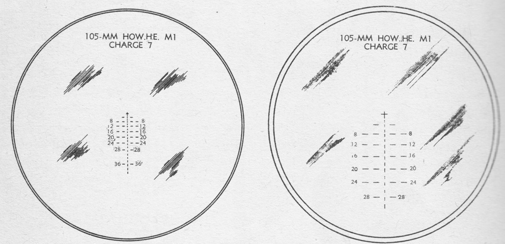
The reticles for the gunner's telescope M72D and telescope M77C in the periscope M4A1 are shown on the left and right, respectively. The M72D was graduated for the high-explosive shell M1 fired at charge 7 with a muzzle velocity of 1,500 ft/sec (460m/s) and a 0.2 mil jump. The cross was at zero range and deflection. The reticle for the M77C was similar. (Picture from TM 9-731AA Medium Tank M4 (105-mm Howitzer) and Medium Tank M4A1 (76-mm Gun).)
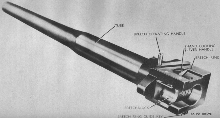
The 105mm howitzer M4 consisted of a tube which screwed into the breech mechanism and was locked in place by a breech ring lock screw. The complete howitzer weighed 1,140lb (517kg) and was 101.3" (257.3cm) long from the muzzle to the rear face of the breech ring. The tube had an estimated accuracy life of 20,000 rounds. (Picture from TM 9-324 105-mm Howitzer M4 (Mounted in Combat Vehicles).)
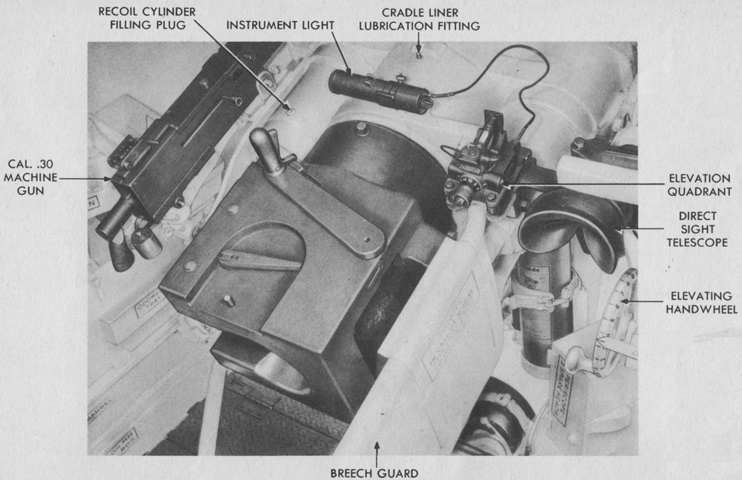
The breech of the 105mm howitzer and coaxial machine gun are shown here. The elevation handwheel featured twenty-five labeled notches, each of which represented 1 mil of elevation or depression. The horizontal sliding wedge breechblock operating handle can be seen atop the breech; the latch on the front of the handle was squeezed to release the handle, then the lever was pulled to the rear and the right to open the breech, which lacked any semiautomatic function. Upon loading, the howitzer shell would slightly move the handle as the lip of its case struck the extractor. This was the signal to close the breech, pushing the operating handle forward until it latched. (Picture from TM 9-731AA Medium Tank M4 (105-mm Howitzer) and Medium Tank M4A1 (76-mm Gun).)
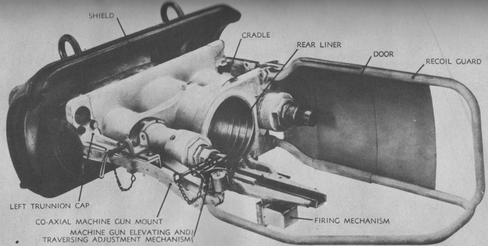
The combination gun mount M52 is seen from the left rear with the howitzer absent. The mount weighed 1,147lb (520.3kg) and with the howitzer mounted was 116" (295cm) long including the recoil guard. (Picture from TM 9-324 105-mm Howitzer M4 (Mounted in Combat Vehicles).)
The combination gun mount M52 is shown from the opposite side with the howitzer installed. (Picture from TM 9-324 105-mm Howitzer M4 (Mounted in Combat Vehicles).)
A cross-section of one of the two hydrospring recoil cylinders is drawn here. Each cylinder contained 9 pints (4.259L) of oil, and the normal and maximum recoil lengths were 13" (33cm) and 14" (36cm), respectively. When the howitzer was fired, the tube and breech ring were driven to the rear. The recoil piston rod in each cylinder moved with the breech, while the cylinder itself remained stationary and fastened to the cradle. Oil in the cylinder was forced around the piston through grooves in the cylinder sleeve as the piston rod was dragged rearward. The grooves tapered to the rear, increasing resistance as the piston moved. This increased resistance as well as the compression of the counterrecoil springs by the piston would arrest the movement of the howitzer. The compressed counterrecoil springs would then expand, pushing the piston forward and the howitzer back into battery. The counterrecoil buffer entered the hole at the front of the piston rod near the end of the counterrecoil stroke, displacing oil trapped in the hole which was then throttled around the buffer, slowing the counterrecoil movement to prevent shock. (Picture from TM 9-324 105-mm Howitzer M4 (Mounted in Combat Vehicles).)
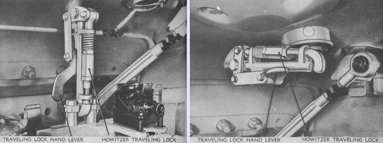
In addition to the travel lock on the hull upper front plate, an internal elevation traveling lock was found in the turret. It is shown engaged on the left and stowed on the right. (Picture from TM 9-324 105-mm Howitzer M4 (Mounted in Combat Vehicles).)
This tank would have similar modifications as the M4A1(76)W above. (Picture from ORD 9 SNL G-104, Vol. 15.)
The more pronounced overhang of the 76mm gun is obvious even with the ordnance depressed into the travel lock. (Picture from TM 9-759 Tank, Medium, M4A3.)
This early turret features the circular split loader's hatch. (Picture from TM 9-759 Tank, Medium, M4A3.)
The engine deck and turret top are labeled in this image. Rests for the engine compartment doors have been added to the upper hull sides; the left one is visible outboard of the towing cable, and the other is just inboard of the shovel. (Picture from TM 9-759 Tank, Medium, M4A3.)
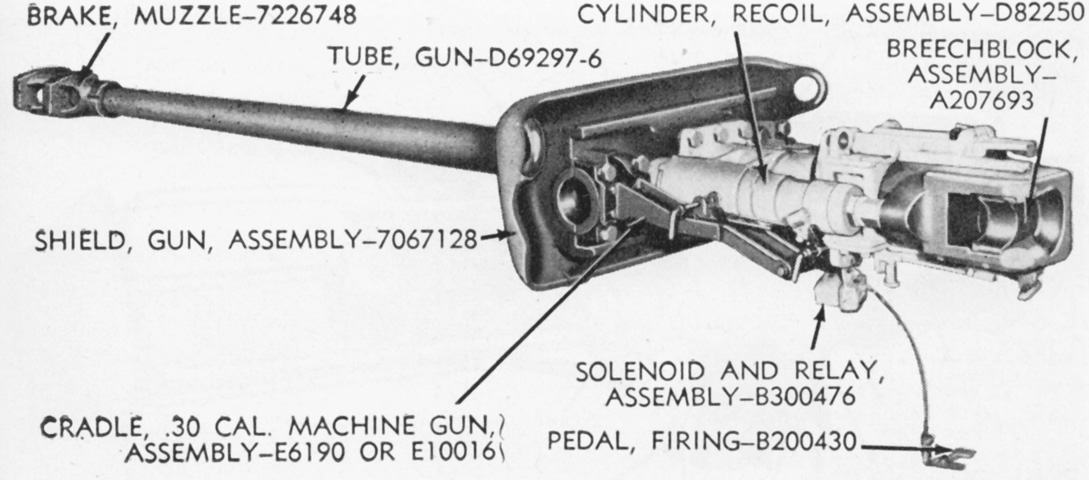
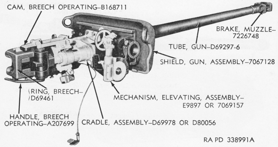
The gun mount M62 is shown here. The complete 76mm gun M1A1C or M1A2 weighed 1,231lb (558.4kg), with the muzzle brake weighing 62lb (28kg). The gun was 163.75" (415.93cm) long overall. (Picture from TM 9-7018 Medium Tank M4A3.)
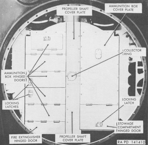
The various lids and compartments in the hull subfloor of a 76mm gun tank can can be seen here. The ammunition boxes on the left featured diagonal stowage, while rounds in the right-side box were stowed horizontally. Ammunition was to be retrieved in the following order: the front half of the racks on the left side of the tank, the rear half of the racks on the left side of the tank, then the horizontal racks on the right side of the tank. The ready rounds were normally reserved for actions where loading speed was paramount, and the horizontal rounds were ideally used to refill the other racks as time permitted. (Picture from TM 9-7018 Medium Tank M4A3.)
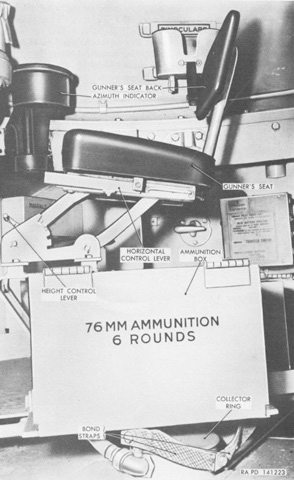
The six-round ready box of ammunition is shown here. The gunner's position is in the background. (Picture from TM 9-7018 Medium Tank M4A3.)
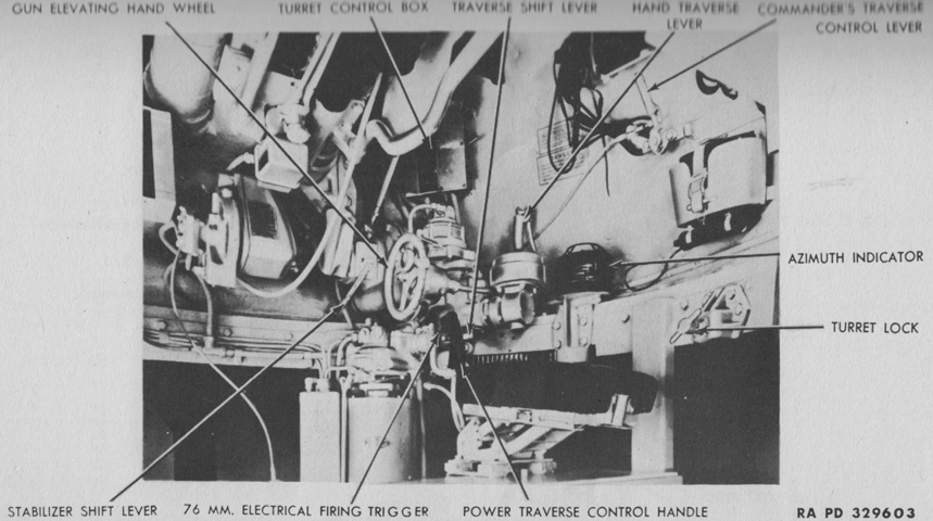
The turret and gun controls are displayed in this picture. (Picture from TM 9-759 Tank, Medium, M4A3.)
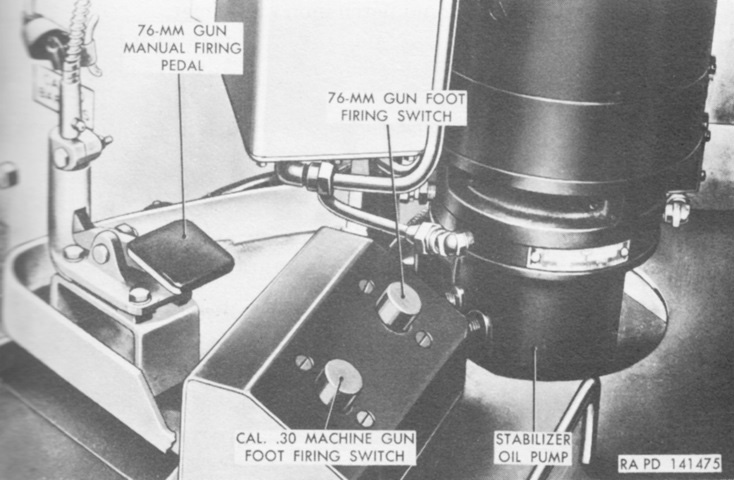
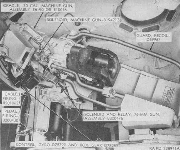
In addition to their hand triggers, gunners in 76mm gun tanks were provided with electrical foot triggers as well as a manual foot firing pedal. (Picture from TM 9-7018 Medium Tank M4A3.)
The reticle for the updated telescope M47A2 used in the periscope M4A1 is sketched. (Picture from TM 9-2300 Artillery Matériel and Associated Equipment.)
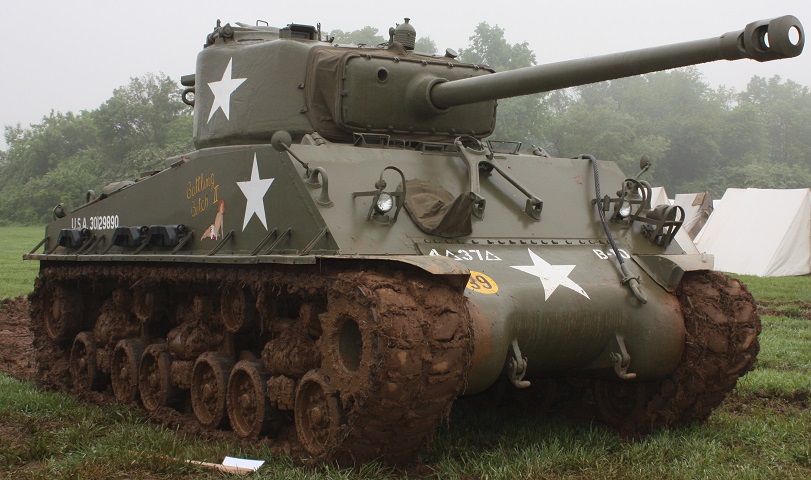
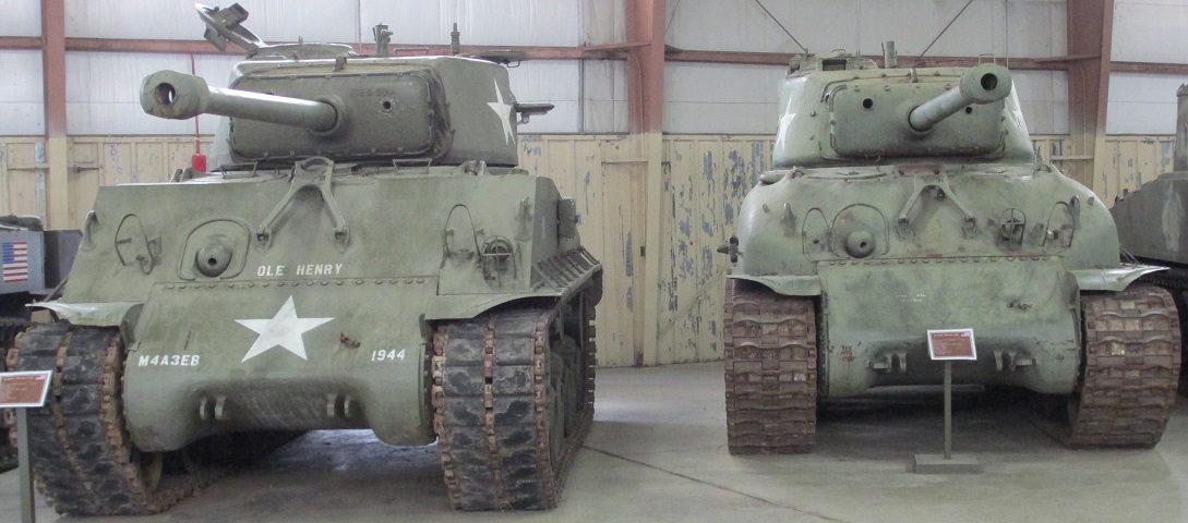
"Battling Bitch II" is one of the 1531 M4A2(76)Ws fitted with horizontal volute spring suspension, and the wide tracks and fenders are immediately obvious compared to the vertical volute spring-suspended tanks. Spare track shoes are stowed on the fenders. This vehicle is armed with the 76mm gun M1A1C or M1A2, both of which were fitted with muzzle brakes, and on the turret roof, the spotlight is mounted and pointed downwards. Compared with the early M4A1 Sherman above, later Sherman tanks are almost unrecognizable. (Photo by Richard S. Eshleman.)
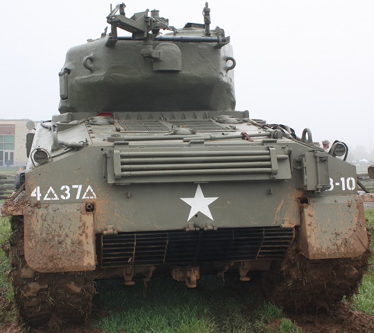
While the front offers few points at differentiating the type of tank, this rear view allows identification. The width of the engine grille doors and location of the fuel, water, and oil filler caps indicate the diesel engine. Note the armored cover behind the engine grille doors over the engine oil gauge referred to above. The exhaust pipe for the auxiliary generator engine can be seen exiting the hole inboard of the left-hand mudguard. Gun cleaning rods are stowed on the blanket roll rack on the hull rear plate, and a sledgehammer and the idler wheel adjusting wrench are stowed on the rear deck aft of the engine grille doors. On the right side of the rear hull plate is mounted an infantry phone box. (Photo by Richard S. Eshleman.)
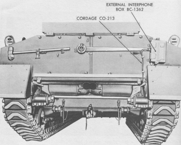
The interphone box and cordage are highlighted in this image. (Picture from TM 9-7018 Medium Tank M4A3.)
The commander's cupola and oval loader's hatch are present on this turret, and the two turret roof ventilators can also be seen, with the rear one under the .50cal machine gun mount. (Picture from TM 9-759 Tank, Medium, M4A3.)
The gunner had not been provided with power traverse at the point this tank was manufactured. A traverse shift lever is present, but instead of changing to power traverse, moving the lever upward shifted the traversing mechanism into neutral position. (Picture from TM 9-759 Tank, Medium, M4A3.)
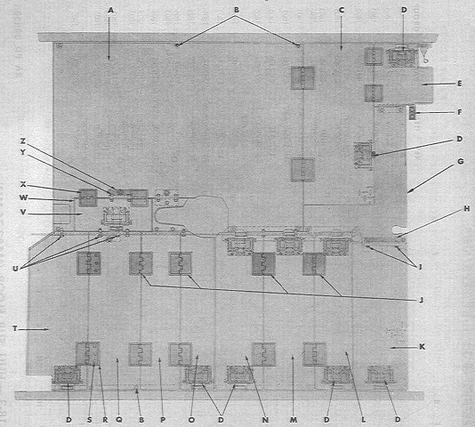
The various lids and compartments in the hull subfloor of a 105mm howitzer tank can can be seen here. (Picture from ORD 9 SNL G-104, Vol. 15.)
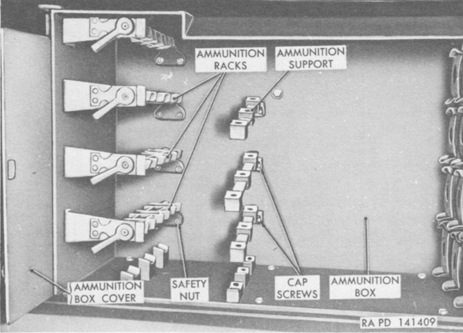
A sponson ammunition box is shown here. The howitzer shells would be stowed horizontally in the box. (Picture from TM 9-7018 Medium Tank M4A3.)
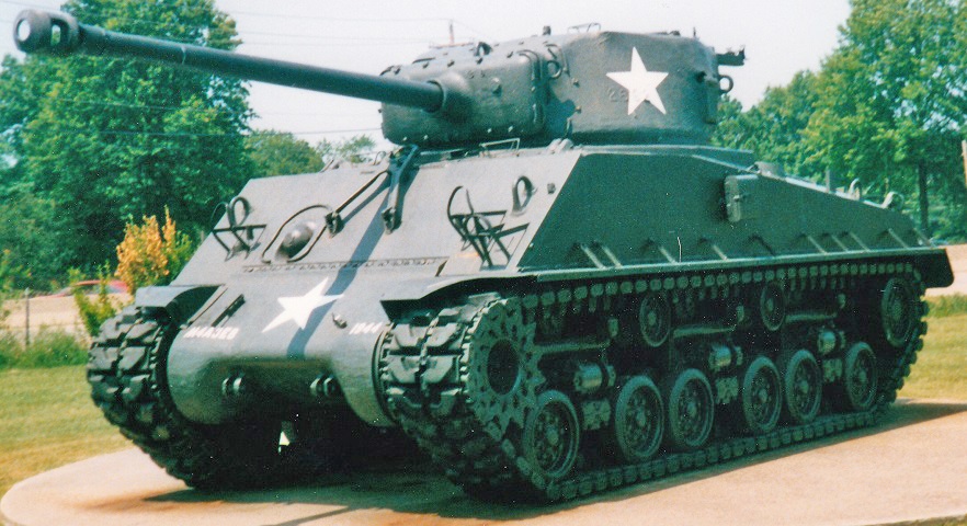
The shape of the heavy new turret mounted on the M4A3E2 can be seen here, and the weld lines for the extra armor applied to the gun shield and hull front can be glimpsed. The commander was provided with a cupola. Extended end connectors have been installed to help lessen the tank's ground pressure. (Picture from Development of Armored Vehicles, volume 1: Tanks.)
Fixtures such as the headlights and siren have been omitted from the hull front, however the bow machine gun was retained. This tank lacks the extended end connectors on its T48 tracks. The gun mount welded in place to the hull is of course not the original, and likewise this machine has been rearmed with the 76mm gun.
The extra armor added to the tank's upper front hull and sides is apparent when one looks at the joining welds.
The final drive and differential cover is noticeably sturdier than on non-assault tanks.
The rear hull armor, however, was unaugmented.
The rear deck also remained the same thickness, with its characteristic full-width air intake grilles.
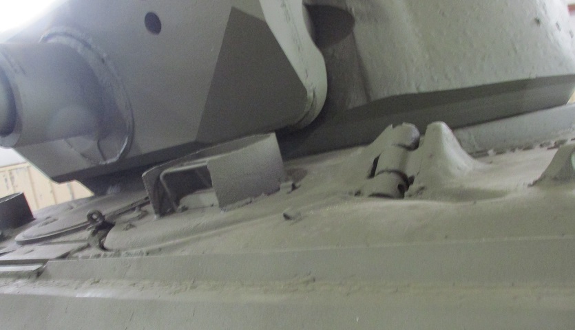
The turret design was based on that of the 76mm gun turret. The ventilator housing is lower relative to the lower edge of the turret rear on the M4A3E2, however, since the extra armor also elongated the turret.
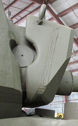
The underside of this turret, cast by the Ordnance Steel Foundry Company, features extensive machining to allow it to clear the hull fixtures. Turrets cast by Union Steel Castings lack this machining and are smoother as they reach down to the hull.
The gun mount T110 was a 76mm gun mount M62 with thick armor welded to its front, and the weld bead for the additional protection can easily be seen in this image. Note that the lower corners of the gun shield had to be angled back to avoid fouling on hull fixtures.
The driver's hatch and periscope with guard can be seen here.
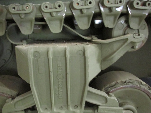
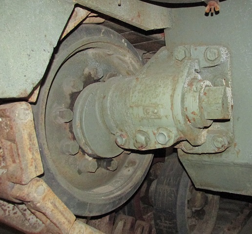
This tank features suspension bogies fitted with the raised arm for the return roller, which helped reduce wear on the track skid from steel track.
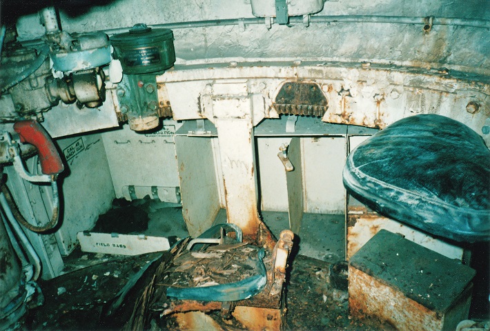
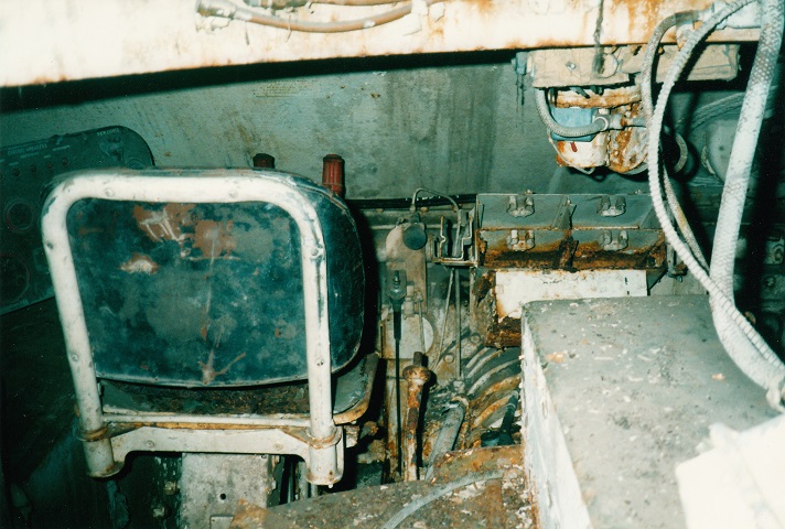
This view is of the right side of the turret. The commander's seat is visible, and the gunner's seat, if present, would be in front of and below the TC's seat. The gunner's red turret traverse handle is near the front of the picture, and the white turret traverse hand lever can just been seen near the top of the picture. The black device near the turret ring is the gunner's azimuth indicator. Stowage in the right sponson included three water cans in the compartment in the center of the picture. The hexagonal hole through which the turret ring is visible would normally be covered by the traverse lock.
This is a more detailed view of the gunner's station. The azimuth indicator is on the far right, the red turret traverse handle is visible again, and the white traverse hand lever can be seen in front of the azimuth indicator. The elevating handwheel has a red handgrip, and the main gun can be seen in the upper left. The turret control box is positioned above the gunner's controls to the front.
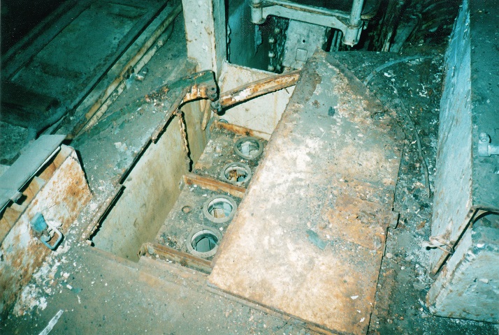
M4A3E2s featured wet ammunition stowage, and an open ammunition rack is illustrated here. The driver's seat is in front of this ammo rack.
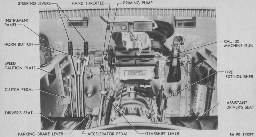
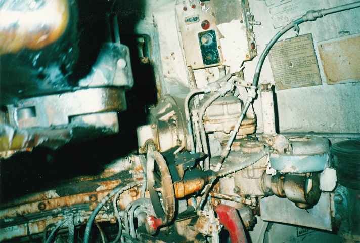
The driver's position is the subject of this photo. The driver and assistant driver were separated by the transmission assembly. The two steering levers can be just seen in front of the driver's seat, and his instrument panel is to the left. The rusted gearshift lever is just to the right of the driver's seat, and the black knob to the right of the steering levers is the hand throttle. The four brackets above the transmission itself were for stowing extra periscopes; spare periscope heads could be stored in the box below the periscopes themselves. Between the drivers on the hull roof is a ventilator fan. The ball mount for the bow machine gun can be seen in the front hull plate on the right of the picture.
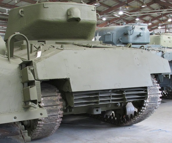
From the front, this M4A3(76)W HVSS is visually virtually identical to the M4A2(76)W HVSS above, although its identity is belied by the posts on the upper hull sides used for supporting the engine air intake grilles when opened. In the center of the 47° glacis is the gun travel lock, and the sharp-nosed single-piece final drive and differential cover is mounted. The tracks on this vehicle are the double-pin T84.
In contrast to the previous machine, this tank has been fitted with sand shields. (Picture from TM 9-7018 Medium Tank M4A3.)
This view shows the later exhaust deflector fitted to the GAA-engined Shermans. It consisted of two armored pieces that could be raised independently. Directly under the blanket rack are supports for the deflectors when they are raised. This tank also has some sections of track mounted incorrectly.
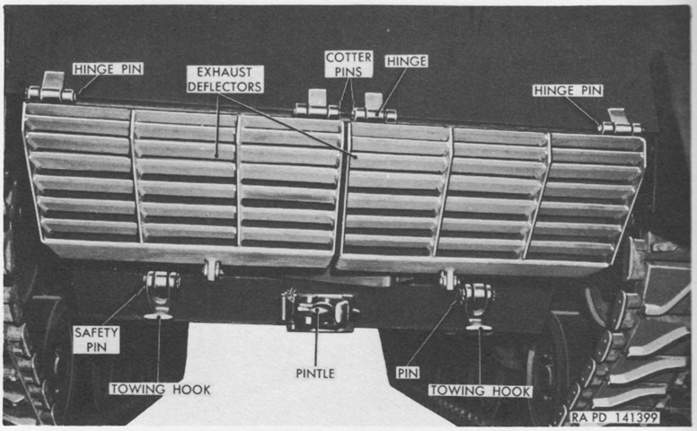
Parts of the deflector and towing equipment are labeled in this image. (Picture from TM 9-7018 Medium Tank M4A3.)
Both halves of the exhaust deflector have been raised and secured to their lugs on the hull rear. (Picture from TM 9-7018 Medium Tank M4A3.)
The shape of the 76mm gun turret can be seen from above. (Picture from TM 9-7018 Medium Tank M4A3.)
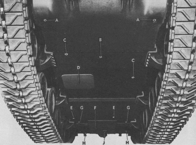
The underside of the hull is shown here, with the front at the top of the image. Attachment of the HVSS bogies to the hull underside can be seen. A. Final drive drain plugs. B. Transmission drain plug. C. Driver compartment drain valves. D. Escape hatch. E. Fighting compartment drain valves. F. Engine compartment access plate. G. Fuel tank drain plugs. H. Engine compartment drain valves. J. Engine oil drain plug. (Picture from TM 9-7018 Medium Tank M4A3.)
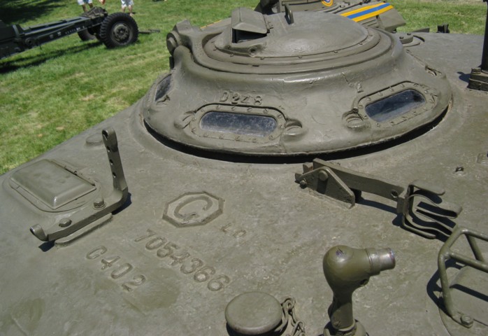
The commander's vision cupola is detailed here. He was provided with a rotating periscope in the cupola door, and six vision blocks ringed the base of the cupola. The revised vane sight is mounted in front of the cupola, and outboard of this is the cover for the gunner's periscope. A stowage clip for the barrel of the roof-mounted machine gun is folded onto the turret roof, and a searchlight mount can be seen towards the bottom right of the image.
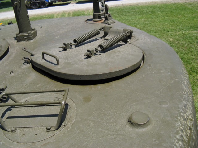
The loader's oval hatch is slightly ajar on this machine. The springs to assist the loader in the hatch's operation are obvious, and a hold-open catch can be seen to the rear in front of the antenna mount. The loader's periscope and guard can be seen in the foreground, and the mounting post for the .50cal MG is in the turret rear between the loader's hatch and commander's cupola.
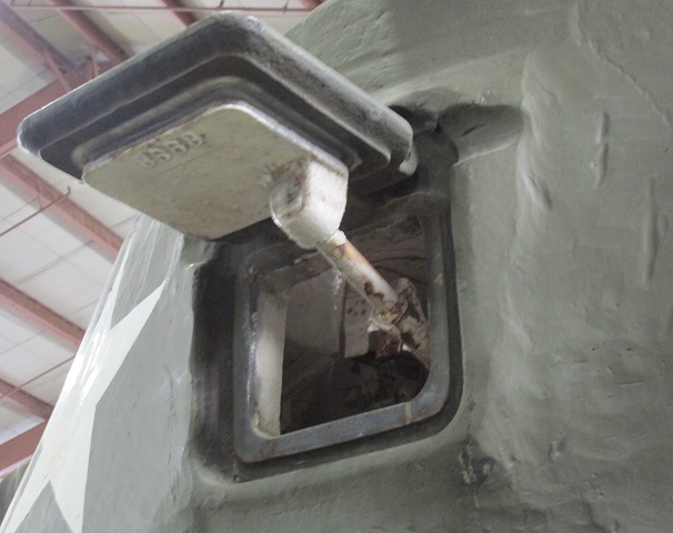
The pistol port is open on this tank, and the mechanism for opening and closing it can be seen.
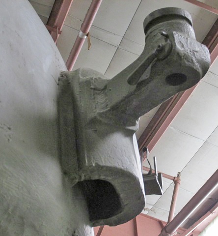
The armored casting for the turret ventilator was substantial, as can be seen here. The welding for the machine gun stowage receptacle is also visible.
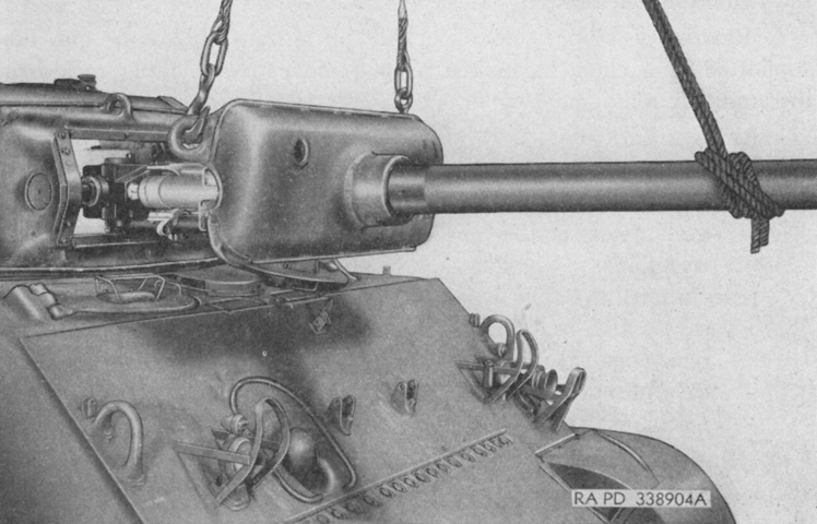
The combination gun mount M62 is being removed from this tank. In contrast to the 75mm combination gun mounts, the M62 did not use separate rotor and gun shields. (Picture from TM 9-1308 Ordnance Maintenance--76-mm Guns M1A1C and M1A2; Gun Mount M1 and Combination Gun Mount M62 for Combat Vehicles.)
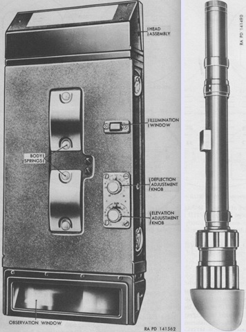
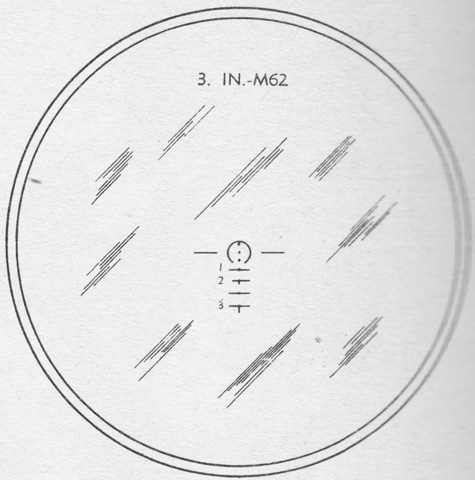
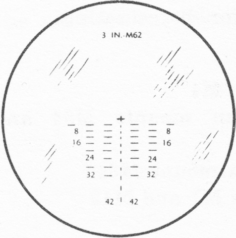
The gunner's periscope M8A1 with telescope M39A2 is on the left, with the telescope M83D on the right. The periscope M8A1 was similar to the M4A1, but was longer (14¾" [37.47cm] versus 11-1/16" [28.0988cm]) and had two clamping knobs at the rear. The M83D was a variable 4x to 8x device with real semifield fields of view of 7°40' at 4x and 4°15' at 8x. The reticle patterns were both identical to that of the telescope M71D, except that of the telescope M39A2 in the periscope M8A1 had "3 in-M62" inscribed at the top instead of "76-M62." (Picture from TM 9-7018 Medium Tank M4A3.)
The periscope M16G was a periscope M16F with a new reticle. The periscope M10G was similar to the M10C except for a new reticle and a spacer between the head and body that raised the head and improved the field of view. The 6x reticle for the M16G and M10G is drawn on the left, with the 1x reticle on the right. (Picture from TM 9-7018 Medium Tank M4A3.)
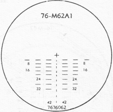
Similarly, the reticle for the gunner's telescope M71P was updated for the 76mm M62A1 projectile. (Picture from TM 9-2300 Artillery Matériel and Associated Equipment.)
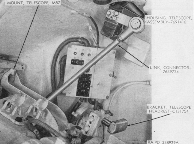
The linkage from the gun mount to the gunner's periscope is seen in this image. The turret control box with the stabilizer adjustment knobs is in the background. (Picture from TM 9-1308 Ordnance Maintenance--76-mm Guns M1A1C and M1A2; Gun Mount M1 and Combination Gun Mount M62 for Combat Vehicles.)
The combination gun mount is illustrated from the loader's side of the turret, but the coaxial machine gun is not present. Note the horizontal orientation of the 76mm gun breech. The commander's cupola can be seen at the upper right of the picture. (Picture from TM 9-1308 Ordnance Maintenance--76-mm Guns M1A1C and M1A2; Gun Mount M1 and Combination Gun Mount M62 for Combat Vehicles.)
The combination gun mount is shown from the bottom. (Picture from TM 9-1308 Ordnance Maintenance--76-mm Guns M1A1C and M1A2; Gun Mount M1 and Combination Gun Mount M62 for Combat Vehicles.)
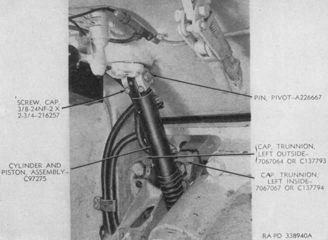
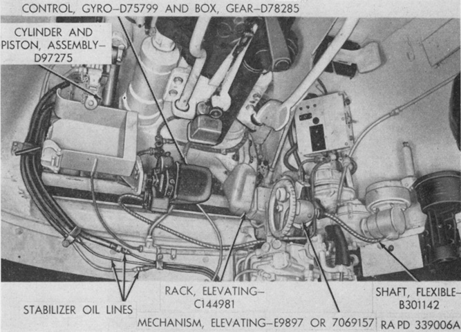
The stabilizer's cylinder and piston connected the upper left corner of the gun mount to the tank's roof. The internal gun travel lock is at the upper right of the image, and the control for the roof-mounted spotlight is at the upper left. (Picture from TM 9-1308 Ordnance Maintenance--76-mm Guns M1A1C and M1A2; Gun Mount M1 and Combination Gun Mount M62 for Combat Vehicles.)
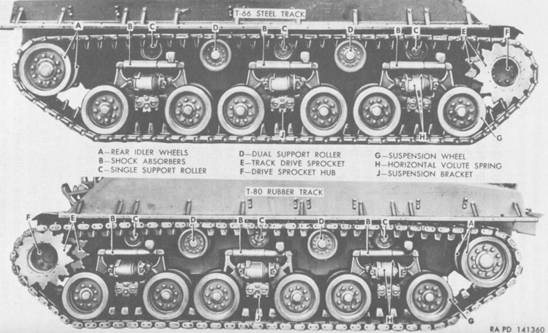
Nomenclature of the horizontal volute suspension system is given in this picture. Note the different center guide shape of the T66 versus T80 tracks. (Picture from TM 9-7018 Medium Tank M4A3.)
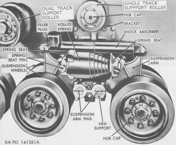
This image provides a closer look at a suspension bogie. Both types of return roller can also be seen. (Picture from TM 9-7018 Medium Tank M4A3.)
The 105mm howitzer and .50cal machine gun are both in their travel locks. (Picture from TM 9-7018 Medium Tank M4A3.)
The exhaust deflector is in position, and the turret rear ventilator can be seen under the .50cal machine gun. (Picture from TM 9-7018 Medium Tank M4A3.)
The two turret ventilators can easily be seen from above. (Picture from TM 9-7018 Medium Tank M4A3.)
The lack of power traverse in 105mm howitzer tanks was corrected once requests from the field were received, however World War II ended before howitzer tanks fitted with power traverse could see service. (Picture from TM 9-7018 Medium Tank M4A3.)
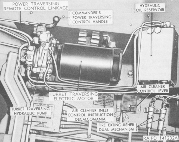
When power traverse was installed, the tank commander received a power traverse control handle as well, but the gunner was the only one with elevation controls. (Picture from TM 9-7018 Medium Tank M4A3.)
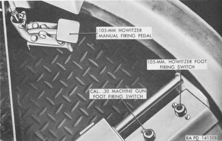
In addition to the electrical howitzer firing button on his hydraulic traversing control handle and the electrical machine gun firing button on his elevation handwheel, the gunner was provided with electrical foot triggers as well as a foot pedal to fire the howitzer manually. (Picture from TM 9-7018 Medium Tank M4A3.)
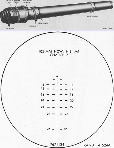
The telescope M76G was a 3x, straight tube instrument with a reticle graduated for the same shell, muzzle velocity, and jump as that found in the telescope M72D. The cross represented zero range and deflection and was used for boresighting. Each part of the broken vertical line represented 100 yards (90m) range, and were numbered in hundreds of yards. Each horizontal line and space represented 5 mils deflection. (Picture from TM 9-7018 Medium Tank M4A3.)
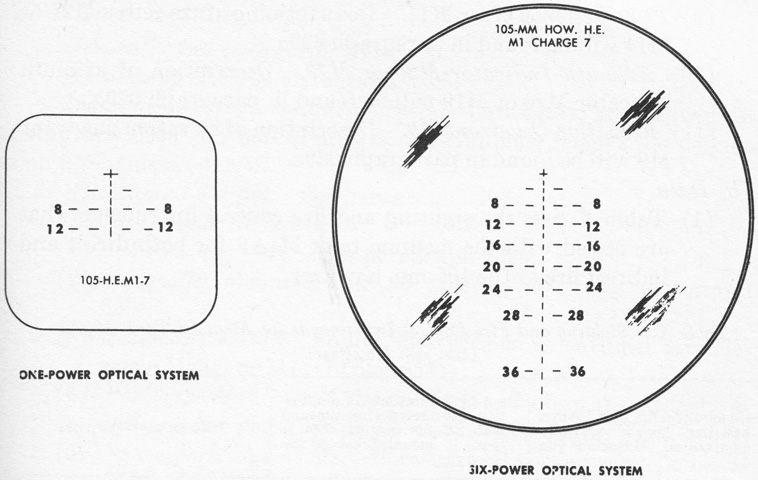
The periscopes M16D and M10D were similar to the M16F and M10C, respectively, but used reticles for the howitzer seen here. (Picture from TM 9-7018 Medium Tank M4A3.)
This somewhat derelict M4A3(105) HVSS Sherman features the armored cover protecting the gunner's telescope. This could be pivoted down out of the way when in action, and a path for its movement has been machined out of the howitzer shield. (Photo by Richard S. Eshleman.)
The underside of the left air intake grille can be seen from the rear, and with the missing tracks the dual nature of the road and idler wheels is visible. (Photo by Richard S. Eshleman.)
The gunner's telescope cover is rotated down on this machine.
