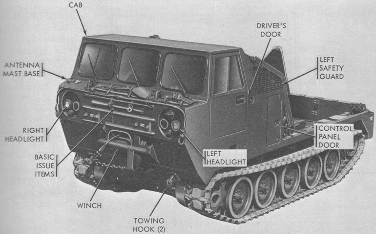
Self-propelled Guided Missile Carrier M727.

The relationship of the M727, seen here without the missile launcher mount installed, to the cargo carrier M548 is obvious. The vehicle weighed 17,550lb (7,961kg) in this configuration, fully equipped and serviced for operation with a driver but without the crew, launcher equipment, or missiles. (Picture from TM 9-1450-501-10.)
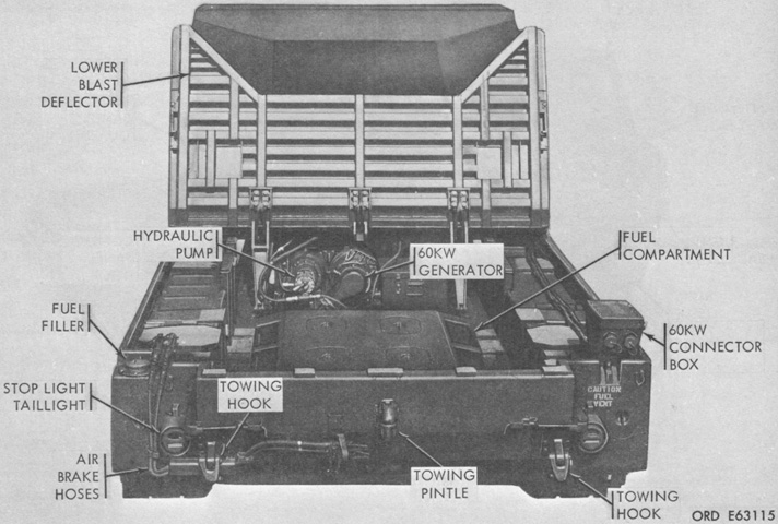
The lower blast deflector is folded forward onto the upper blast deflector, revealing equipment found in the rear compartment. (Picture from TM 9-1450-501-10.)
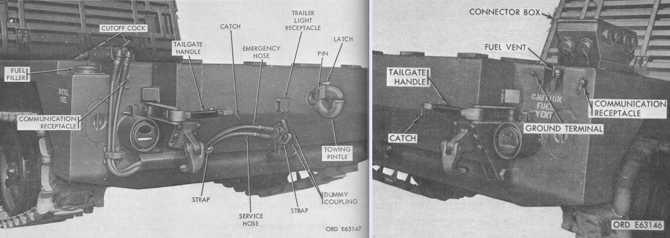
Further details of the hull rear are seen here. The connector box provided outlets for the 60 kilowatt generator. Note the towing pintle was installed on the tailgate; the maximum towed load was 14,500lb (6,580kg). The tailgate was nominally 64" (160cm) wide. Two latches secured the tailgate, and both needed to be released in order to lower it. When the missile equipment was installed, the tailgate was raised and lowered hydraulically; when the launcher was absent the tailgate was lowered simply by gravity, and care needed to be taken when the latches were released to prevent injury. (Picture from TM 9-1450-501-10.)
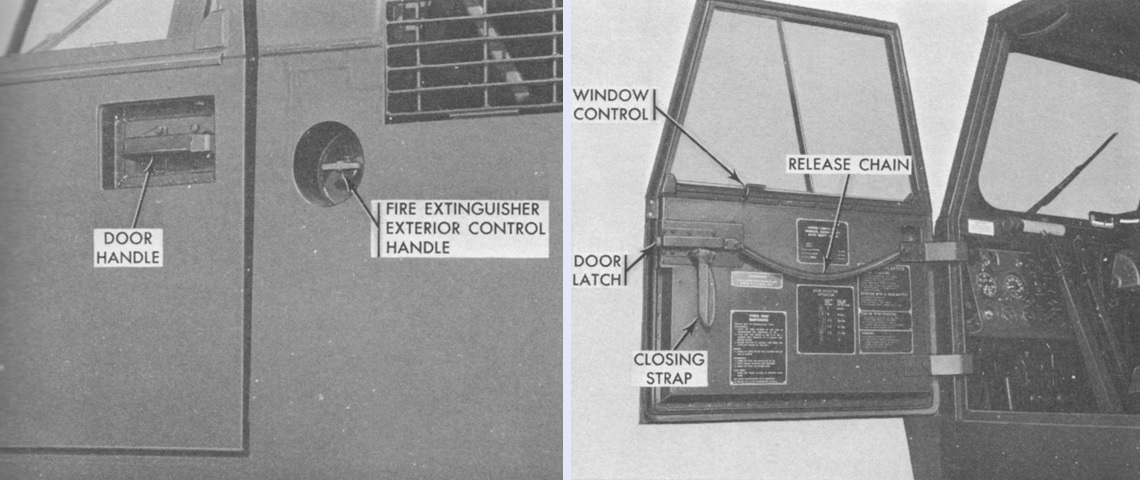
The exterior cab door handle was attached directly to the latch. The door was opened from the interior by pulling on a rubber-covered chain with one end secured to the door and the other to the latch. The side window could be slid to the front or rear by pulling up on the spring-loaded window control. (Picture from TM 9-1450-501-10.)
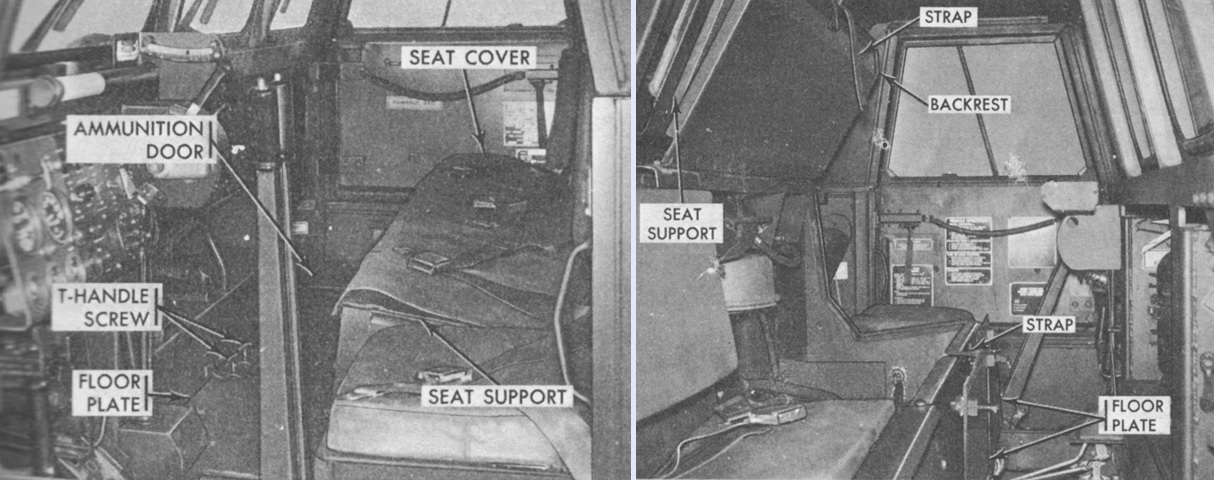
The cab interior is shown from the driver's side on the left and the passenger's side on the right. Powerplant access was via plates and covers in the cab; these are closed in the left image and open on the right. (Picture from TM 9-1450-501-10.)
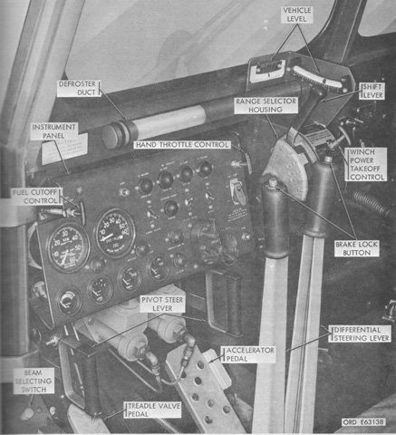
The driver's controls would seem familiar to those comfortable with the M548. (Picture from TM 9-1450-501-10.)
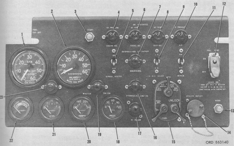
The driver's instrument panel did undergo some revisions, however. 1. Tachometer. 2. Speedometer. 3. Start switch. 4. Engine oil low pressure warning light. 5. Air box heater switch. 6. Transmission oil high temperature warning light. 7. Suspension lockout warning light. 8. Differential oil high temperature warning light. 9. Infrared-blackout selecting switch. 10. Trailer brake air low pressure warning light. 11. Windshield wiper switch. 12. Fuel pump switch. 13. Horn switch. 14. Utility outlet receptacle. 15. Driving light selector switch. 16. Hydraulic pump on indicator light. 17. Headlight hi-beam indicator light. 18. Trailer brake air pressure indicator. 19. Master switch on indicator light. 20. Engine coolant temperature indicator. 21. Fuel quantity indicator. 22. Battery-generator indicator. 23. Instrument panel light. (Picture from TM 9-1450-501-10.)
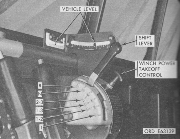
The ranges of the transmission range selector and shift lever are labeled above. Two neutral start switches below the selector housing prevented both the engine and the 60 kilowatt generator from starting if the lever was not in the N position. Two levels on top of the range selector housing were used to inform the crew when the vehicle was properly positioned for launching missiles. The vehicle was to have no more than a 2° roll in either direction or 10° nose-down to level. (Picture from TM 9-1450-501-10.)

The lower blast deflector is shown stowed for travel on the left and prepared for missile launch on the right. (Picture from TM 9-1450-501-10.)
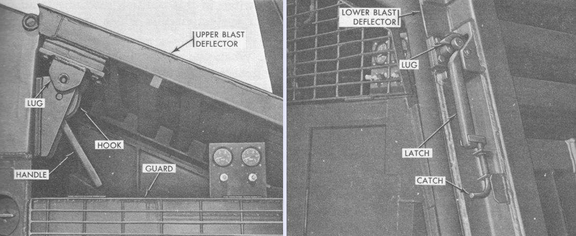
The blast deflectors were secured by latches. The upper deflector was secured to the cab by two latches, one of which is seen on the left, that could be released to provide access for vehicle maintenance. The lower deflector was attached to the upper deflector by two latches, as seen on the right, which were released to deploy the deflector in preparation for missile launch. (Picture from TM 9-1450-501-10.)
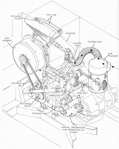
The engine air intake and cooling system is diagrammed in this schematic. The cooling system used 9.5 gallons (36L) of coolant. (Picture from TM 9-1450-501-10.)
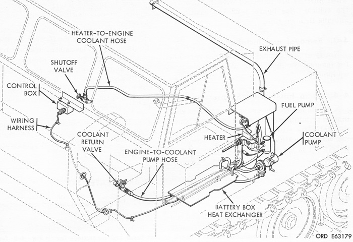
In temperatures of -25°F to -65°F (-32°C to -54°C), a kit could be installed to heat the engine coolant to facilitate starting. The kit heated and circulated the coolant through the engine and a heat exchanger in the battery compartment. When the warm engine was turned off, the kit was started so that the lubricating oil, engine block, and battery electrolyte was kept warm for up to 12 hours. The heater was a Stewart-Warner Model 939-J24 that produced 16,000BTU/hour in high heat mode and 5,500BTU/hour in low heat mode. (Picture from TM 9-1450-501-10.)
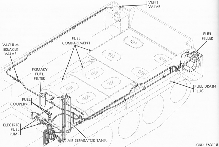
The fuel system is sketched here. The fuel compartment was located in the hull under the launcher equipment area, and the main engine and personnel heater were both plumbed into the same fuel system. (Picture from TM 9-1450-501-10.)
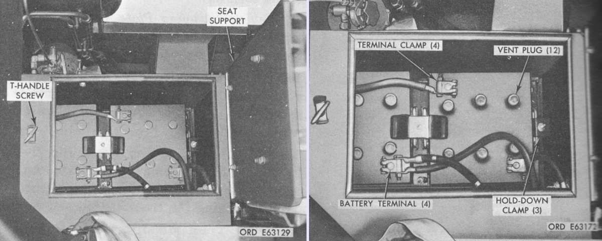
Located in a box under the driver's seat, two 12-volt batteries were connected in series for the 24-volt electrical system. (Picture from TM 9-1450-501-10.)
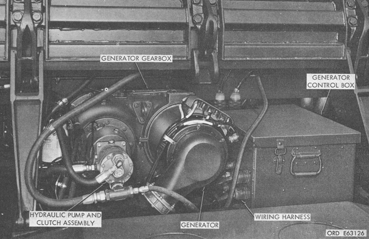
The General Electric Model 2CM355B2 air-cooled self-lubricated brushless AC generator provided electrical power to operate the missile system's electrical equipment. The FMC generator gearbox was connected to the transfer gearcase and transmitted mechanical power to drive both the AC generator and the hydraulic system pump. Two electrically-operated clutches permitted the generating system and hydraulic pump to be operated together or separately. The generator gearbox had two front-mounted power take-offs that drove the gearbox lubricating pump and the governor actuator pump. The generator operated at 6,000rpm with the main engine at ~2,000rpm. The generator control box contained the voltage regulator, relays, and engine electric governor control units. (Picture from TM 9-1450-501-10.)

The generator-launcher control box was on the left side of the vehicle behind the cab, and contained the launcher, generator, and hydraulic electrical control panels. Two generating systems could be paralleled, and the synchronizing lamps, generators control switch, and output shunt switch were used during this process. 1. Override switch. 2. Hydraulic panel light. 3. Hydraulic pump switch. 4. Hydraulic panel light switch. 5. Suspension lockout switch. 6. Power breaker switch. 7. Launcher control panel. 8. Generator control panel. 9. Wattmeter. 10. Voltage adjust knob. 11. Voltage selector switch. 12. Protection switch. 13. Generator panel light switch. 14. AC power switch. 15. Communication receptacle. 16. Generators output shunt switch. 17. Generators control switch. 18. Generators synchronizing lamp. 19. Generator system switch. 20. Frequency adjust knob. 21. Frequency meter. 22. Hydraulic control panel. 23. Override light. 24. Hydraulic pump light. 25. Reservoir oil low level light. 26. Suspension lockout light. 27. Reservoir oil high temperature light. 28. Generator panel light. 29. AC voltmeter. (Picture from TM 9-1450-501-10.)
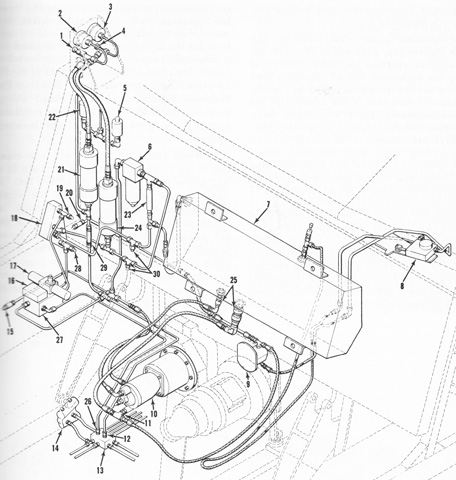
The hydraulic system for the missile launcher and suspension lockout systems is diagrammed. The system also operated the blast deflector. The reservoir was mounted on the front of the upper blast deflector, and held ~7 gallons (~27L) of oil. The New York Air Brake Co. Model 66WA 300C1 variable-delivery hydraulic pump was connected to and driven by the 60 kilowatt generator gearbox, and a hand pump for emergency use was supplied as part of the launcher equipment. 1. Lockout accumulator charge valve. 2. Lockout pressure indicator. 3. System pressure indicator. 4. System accumulator charge valve. 5. Lockout disengaged pressure switch. 6. Filter assembly. 7. Hydraulic reservoir. 8. Engine governor actuator. 9. Actuator hydraulic pump. 10. Hydraulic pump and clutch assembly. 11. Pump filter union. 12. Disengage fitting. 13. Lockout inlet manifold. 14. Suspension lockout cylinder. 15. Hand pump return fitting. 16. Lockout pilot check valve. 17. Lockout directional control valve. 18. System control valve manifold. 19. Launcher equipment supply fitting. 20. Hand pump supply fitting. 21. Lockout accumulator. 22. Lockout engage pressure switch. 23. Pressure relief valve. 24. System accumulator. 25. Coupling assembly. 26. Engaged fitting. 27. Lockout hydraulic manifold. 28. Launcher equipment return fitting. 29. Restriction valve. 30. Pressure test fitting. (Picture from TM 9-1450-501-10.)
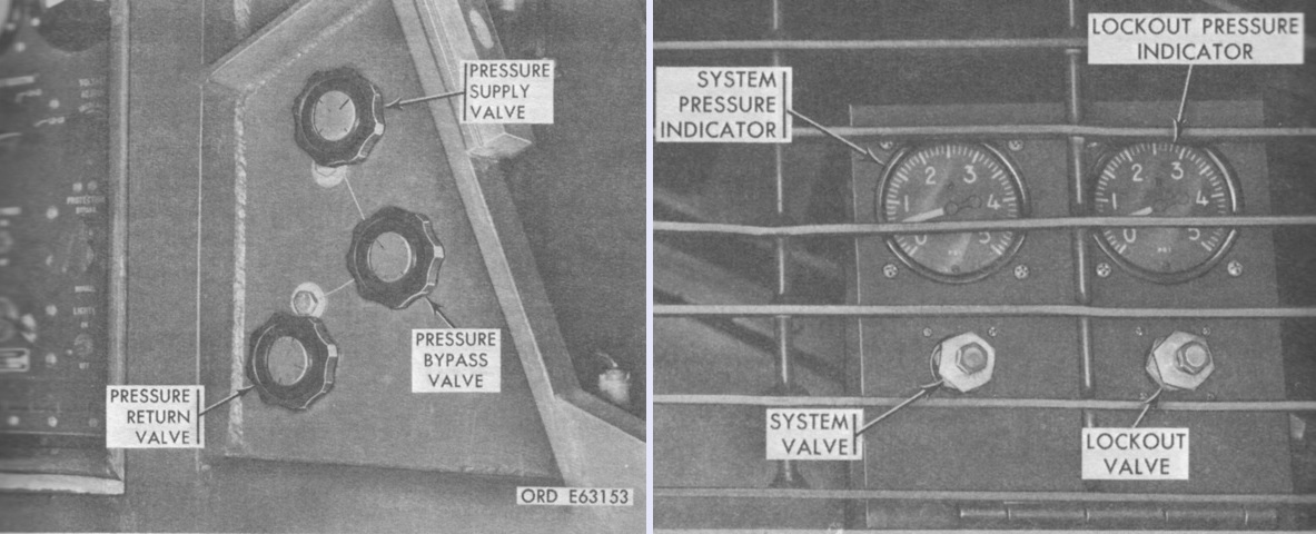
The suspension lockout and launcher hydraulic system control valves are shown on the left, and the system's pressure indicators and accumulator charge valves are on the right. The former were located at the rear of the generator-launcher control box, and the pressure supply and return valves were to be fully opened when the hydraulic system was operating, while the bypass valve was to be fully closed. The pressure indicators and charge valves were located on a bracket behind the left guard. The system pressure indicator would read between 1,000-2,750psi (70-193kg/cm²) when the hydraulic system was charged, while the lockout pressure indicator would read between 500-2,750psi (35-193kg/cm²) if the lockout cylinders were disengaged and 500psi (35kg/cm²) or the accumulator charge pressure with the cylinders engaged. The system accumulator charge valve was used to charge the system accumulator with 1,000psi (70kg/cm²) of nitrogen, and the lockout accumulator charge valve was used to charge the lockout accumulator with 500psi (35kg/cm²) or nitrogen. (Picture from TM 9-1450-501-10.)
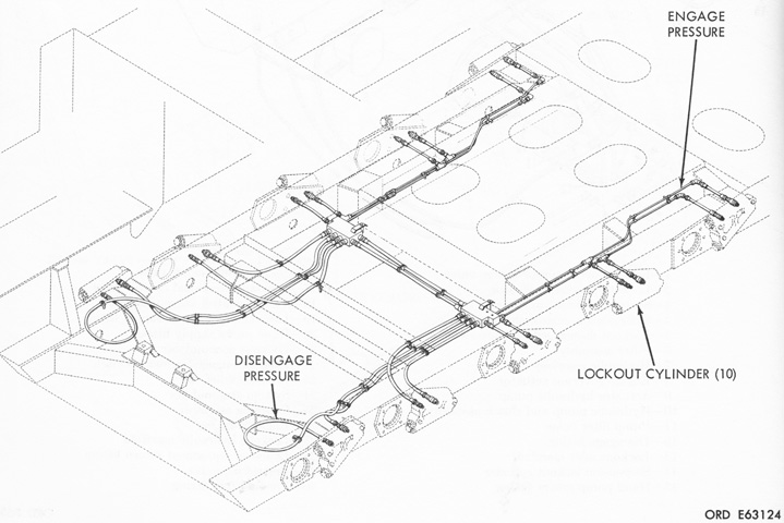
An hydraulically-actuated lockout cylinder was mounted to the rear of each road wheel arm, and prevented the arms from moving during missile launch. (Picture from TM 9-1450-501-10.)
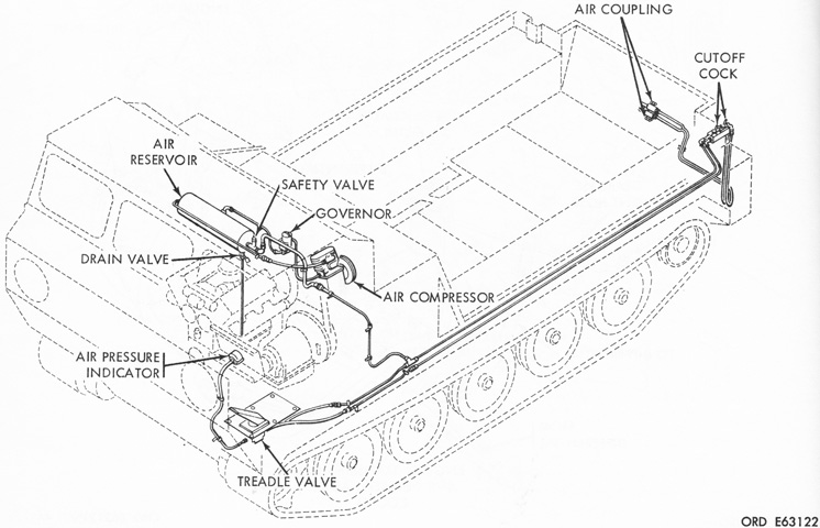
A Bendix-Westinghouse Co. Tru-Flo series 400 air-cooled reciprocating air compressor was used to supply pressure for the trailer air brake system. The compressor's capacity was 7¼cfm (.205m³/min), and it was driven by belts from a power takeoff on the transfer gearcase. The driver was provided with a treadle valve pedal that actuated system pressure when depressed. Normal operating pressure for the system was 90psi (6.3kg/cm²); the governor was set at 85-105psi (6.0-7.38kg/cm²), while the safety valve would open above 150psi (10.5kg/cm²) and the low pressure light illuminated below 60psi (4.2kg/cm²). (Picture from TM 9-1450-501-10.)
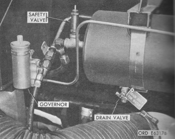
The Bendix-Westinghouse air reservoir is isolated here. Its maximum hydrostatic pressure was 250psi (18kg/cm²), and the drain valve allowed water to be removed after operation of the system. (Picture from TM 9-1450-501-10.)
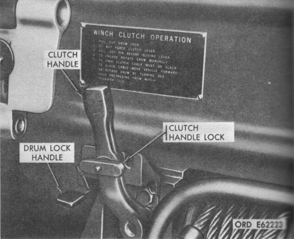
A 20,000lb- (9,000kg-) capacity Gar Wood winch was found in a well in the hull front, and was mainly intended for self-recovery. The winch power takeoff from the transmission was engaged in the cab, and the clutch control handle seen here engaged the winch drum. To engage the drum, the clutch handle lock was pulled out and the clutch handle was pulled to the left. Pulling the clutch handle lock out and pushing the handle to the right disengaged the drum. The drum lock handle was pulled down and to the left to disengage the drum lock, and pushed to the right to engage the drum lock. Two hundred feet (61m) of ⅝" (1.59cm) wire rope was wound on the drum, and line speed with a 20,000lb (9,000kg) load was 30'/min (9m/min). (Picture from TM 9-1450-501-10.)
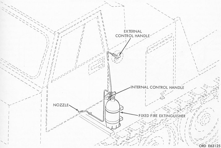
The fixed fire extinguisher system for smothering fires in the engine compartment was to the driver's left rear. The external control handle was behind the driver's door. (Picture from TM 9-1450-501-10.)

The 5lb (2.3kg) CO2 fixed fire extinguisher could be actuated internally by controls located on the bottle head, which could either be a knob or handle as seen in the left and center above. In addition, a 5lb (2.3kg) CO2 portable extinguisher was kept in a bracket on the cab utility compartment floor, as shown on the right. (Picture from TM 9-1450-501-10.)
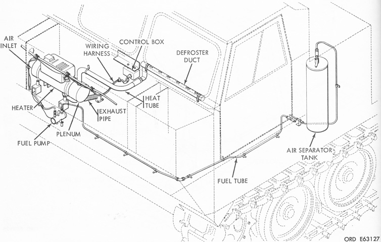
A Stewart-Warner Model 8430-C24 heater was used to warm the crew cab and defrost the windshield. At +70°F (+21°C), the heater produced 30,000BTU/hr in high heat mode and 14,000BTU/hr in low heat mode. Exhaust fumes were expunged via a pipe that exited in the winch well. (Picture from TM 9-1450-501-10.)
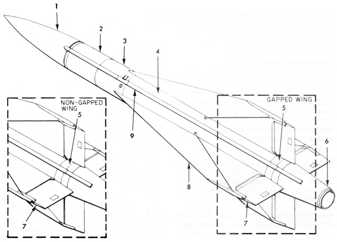
The radar-guided MIM-23A HAWK entered service in 1959. It was 198" (503cm) long, 14" (36cm) in diameter, and weighed 1,295lb (587.4kg). Its single-chamber, dual-grain rocket motor used concentrically cast booster and sustainer propellants to accelerate the missile to ~Mach 2.5, and it had a range of 22 miles (35km). The MIM-23B Improved HAWK debuted in November 1972. Its length increased to 201.6" (512.1cm), weight to 1,380lb (626kg), and range to 25 miles (40km). An Improved HAWK is diagrammed in this image. 1. Radome. 2. Guidance section. 3. Warhead section. 4. Rocket motor. 5. Actuator section. 6. Tailcone. 7. Elevon. 8. Wing. 9. Tunnel. (Picture from TM 9-1410-530-14 C15.)
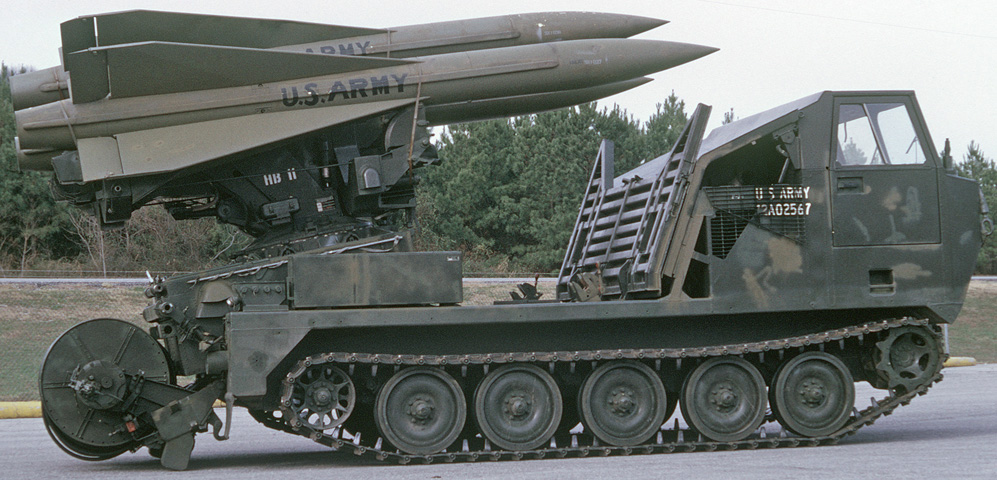
The launcher equipment and three of the large missiles are mounted. The vehicle was 103.5." (262.9cm) tall to the top of the launcher. The lower blast deflector is secured to the upper deflector for travel, and the tailgate is lowered with the launcher moved rearward. For travel, the launcher equipment could be moved toward the cab, and the cable reel on the inside of the tailgate tucked behind the launcher as the tailgate closed. (Picture taken 1 Dec 1973; available from the National Archives.)