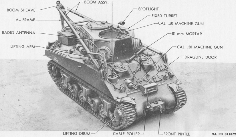
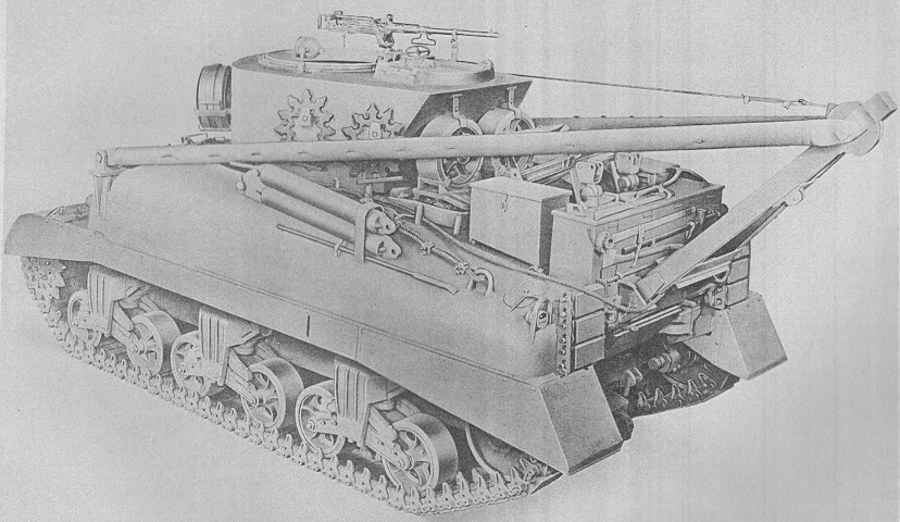
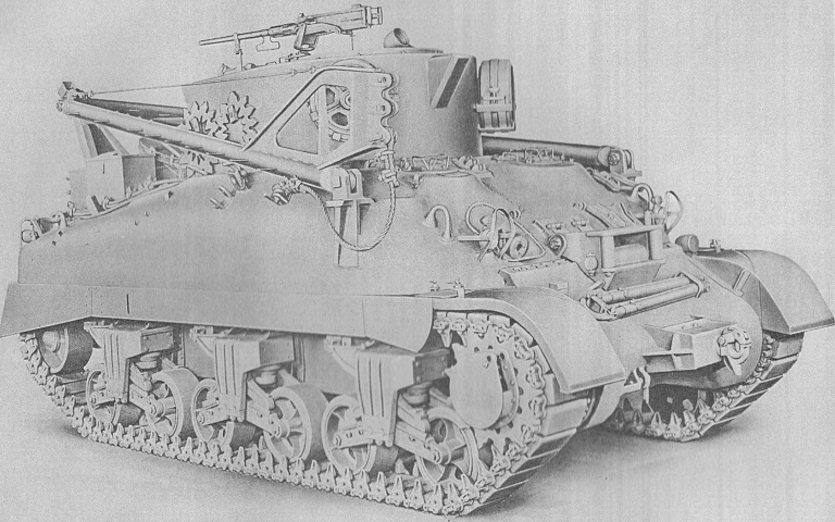
Tank Recovery Vehicle M32B2.
Features found on an early vehicle with the flat-plate turret are labeled here. (Picture from TM 9-738 Tank Recovery Vehicles M32, M32B1, M32B2, M32B3, and M32B4.)
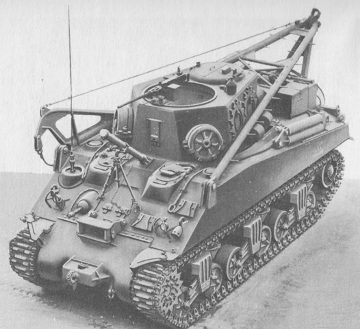
The opposite side is highlighted in this image. (Picture from TM 9-738 Tank Recovery Vehicles M32, M32B1, M32B2, M32B3, and M32B4.)
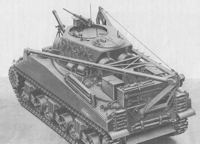
Rear stowage is shown in this picture. (Picture from TM 9-738 Tank Recovery Vehicles M32, M32B1, M32B2, M32B3, and M32B4.)
Stowage on the opposite side can be seen. (Picture from TM 9-738 Tank Recovery Vehicles M32, M32B1, M32B2, M32B3, and M32B4.)
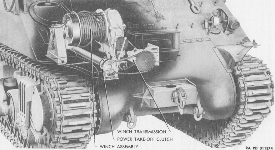
The position of the Gar Wood Special 6M 814 left-hand winch is shown in this ghosted image. Its drum to worm drive gear ratio was 20:1, and it featured a Gar Wood 7 Y 2000 E transmission with 2 forward speeds and 1 reverse. Once the power take-off and winch control levers had been engaged, the winch was powered by the accelerator pedal of the vehicle. An automatic safety brake would hold the load in place if winching was stopped. This close view of the left front fender also highlights the plate that was welded to it to allow the mounting of a vise. A similar plate was found on the right front fender. (Picture from TM 9-738 Tank Recovery Vehicles M32, M32B1, M32B2, M32B3, and M32B4.)
The winch cable is shown here threaded for winching operations. (Picture from TM 9-738 Tank Recovery Vehicles M32, M32B1, M32B2, M32B3, and M32B4.)
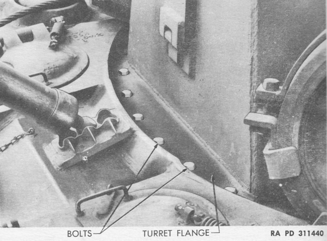
The turret was fixed to the hull roof by a flange secured by bolts and lock nuts. The bottom of the front port through which the winch cable emerged can be seen; a similar port could be found on the turret rear. (Picture from TM 9-738 Tank Recovery Vehicles M32, M32B1, M32B2, M32B3, and M32B4.)
The winch cable can be seen here threaded through the rear port. Spare road wheels, return rollers, and drive sprockets are stowed around the turret, and two snatch blocks can be seen stowed atop two chock blocks in the foreground. (Picture from TM 9-738 Tank Recovery Vehicles M32, M32B1, M32B2, M32B3, and M32B4.)
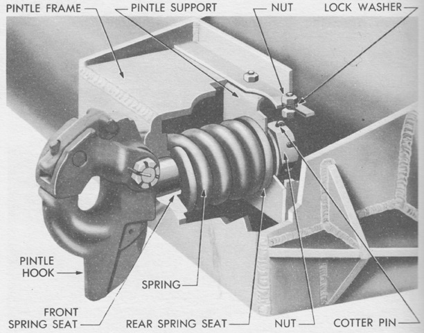
Interior details of the front towing pintle are shown here. (Picture from TM 9-738 Tank Recovery Vehicles M32, M32B1, M32B2, M32B3, and M32B4.)
The boom lifting cable was normally stowed on the hull roof. (Picture from TM 9-738 Tank Recovery Vehicles M32, M32B1, M32B2, M32B3, and M32B4.)
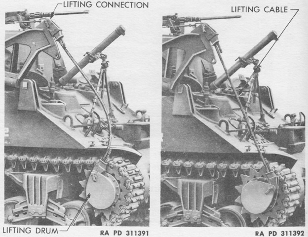
To raise the boom, the lower socket was instead attached to the lifting drum on the right drive sprocket. The tank was then slowly driven forward. (Picture from TM 9-738 Tank Recovery Vehicles M32, M32B1, M32B2, M32B3, and M32B4.)
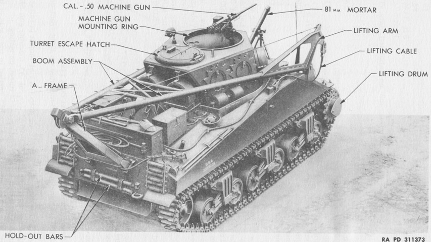
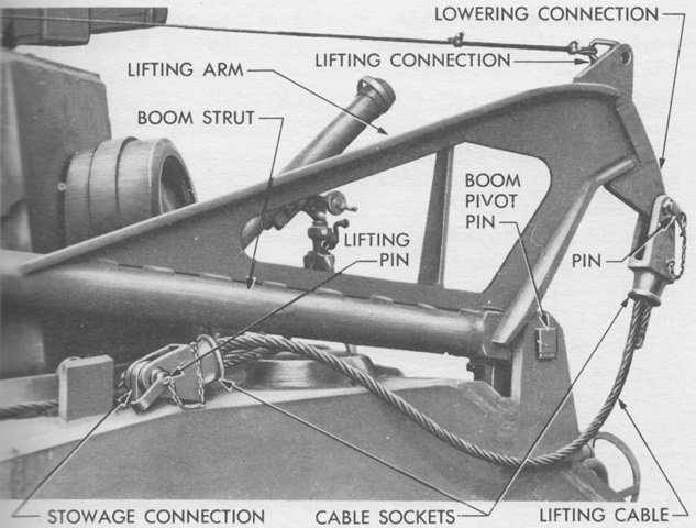
The boom is partly raised in this image, and the nomenclature of various parts is given. (Picture from TM 9-738 Tank Recovery Vehicles M32, M32B1, M32B2, M32B3, and M32B4.)
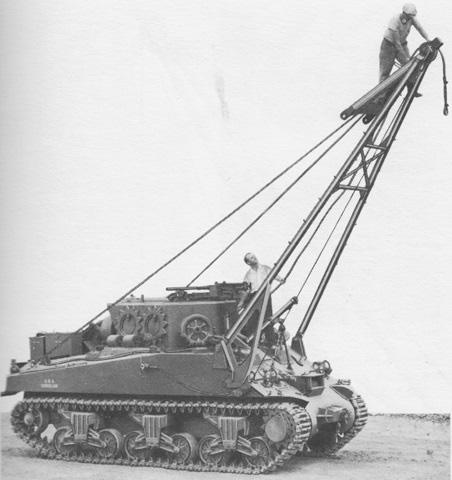
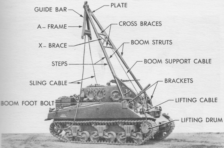
Once past vertical, the boom would fall forward until arrested by the boom sling cable. The winch cable is being threaded over the boom sheave here. The boom was ~21' (~6.4m) above the ground in the forward position. (Picture from TM 9-738 Tank Recovery Vehicles M32, M32B1, M32B2, M32B3, and M32B4.)
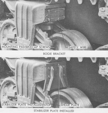
Stabilizer plates, stowed on the hull front, were installed on the front and rear suspension bogies if the load to be lifted was over 10,000lb (4,500kg). With the plates installed, movement over rough terrain was limited to 2mph (3kph) since they eliminated all springing from those bogies. (Picture from TM 9-738 Tank Recovery Vehicles M32, M32B1, M32B2, M32B3, and M32B4.)
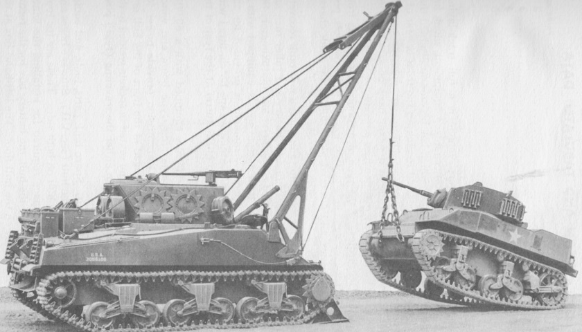
The stabilizer plates are installed and chock blocks have been locked to the tracks in front of the vehicle as a light tank M5A1 is lifted by the boom in front. (Picture from TM 9-738 Tank Recovery Vehicles M32, M32B1, M32B2, M32B3, and M32B4.)
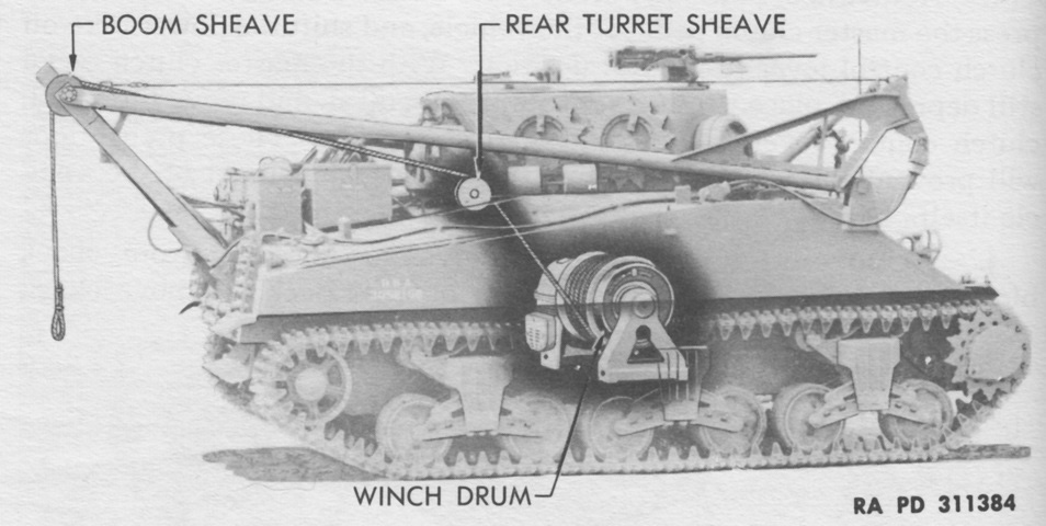
The winch line is shown here threaded through the turret rear over the boom sheave to lift a load at the rear. (Picture from TM 9-738 Tank Recovery Vehicles M32, M32B1, M32B2, M32B3, and M32B4.)
An M5A1 is lifted from the rear of the M32B2. The stabilizer plates are still installed, however their position on the front of the bogies can do little to prevent the suspension from accommodating the rearward shift in weight. (Picture from TM 9-738 Tank Recovery Vehicles M32, M32B1, M32B2, M32B3, and M32B4.)
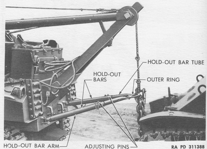
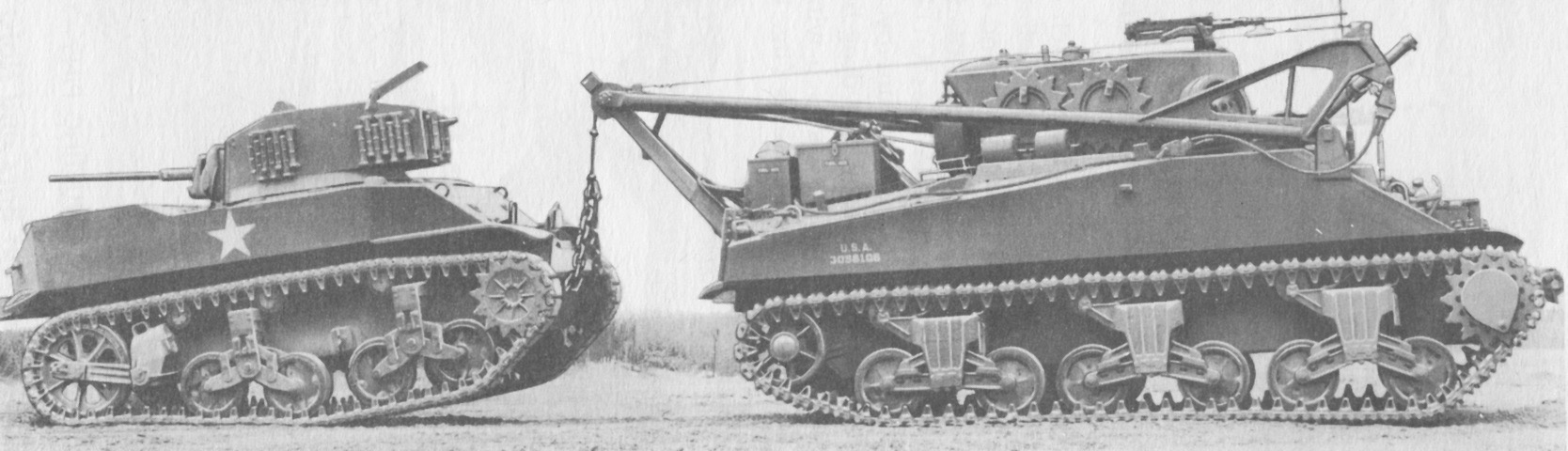
In addition to the usual tow cables and bars, the M32B2 could use its boom to tow disabled vehicles. The boom cable was passed through the ring of the adjustable hold-out bars to keep the load from swinging or crashing into the recovery vehicle. (Picture from TM 9-738 Tank Recovery Vehicles M32, M32B1, M32B2, M32B3, and M32B4.)
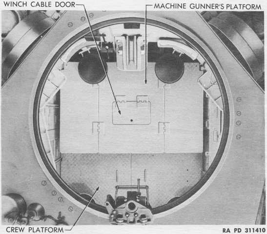
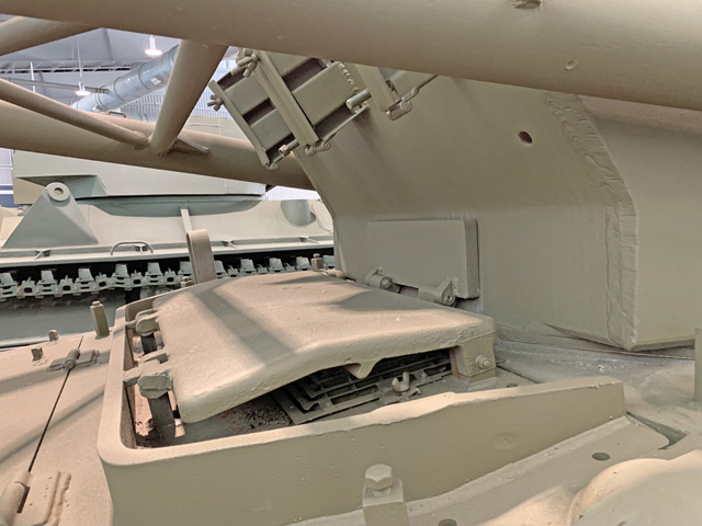
This view is looking down into the machine gun ring. The forward crew seats visible above the machine gunner's platform could be swung outward into the hull sponsons. The other two turret seats, barely visible at the turret rear, were folding. The winch drum was directly under the winch cable door. (Picture from TM 9-738 Tank Recovery Vehicles M32, M32B1, M32B2, M32B3, and M32B4.)
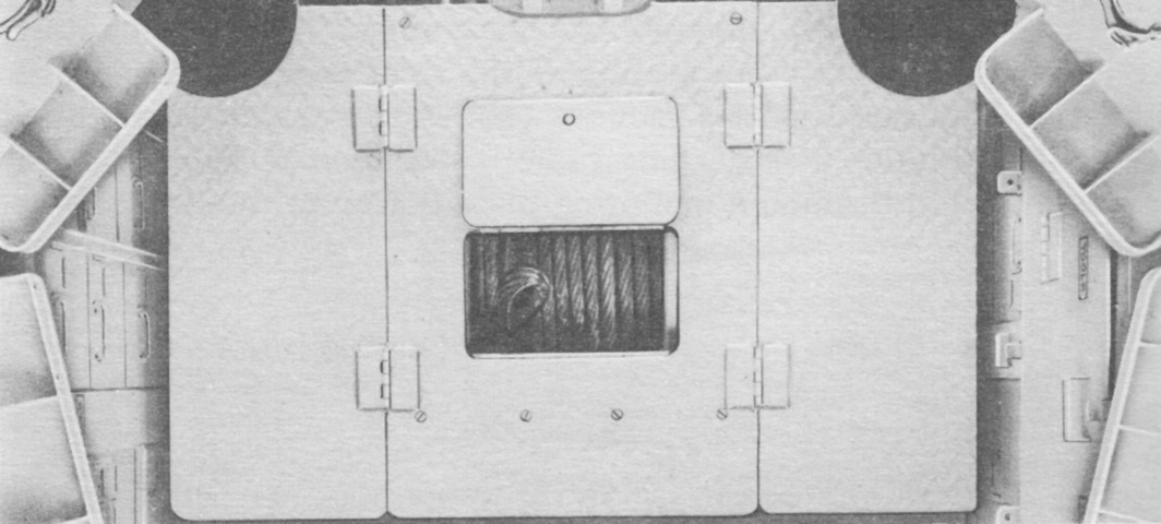
The winch drum can be seen with the winch cable door opened. (Picture from TM 9-738 Tank Recovery Vehicles M32, M32B1, M32B2, M32B3, and M32B4.)
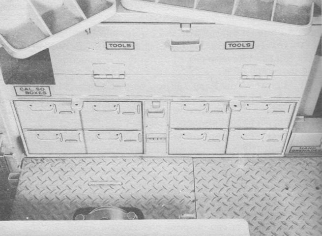
Stowage boxes for tools, spare parts, and ammunition were installed in both sponsons. (Picture from TM 9-738 Tank Recovery Vehicles M32, M32B1, M32B2, M32B3, and M32B4.)
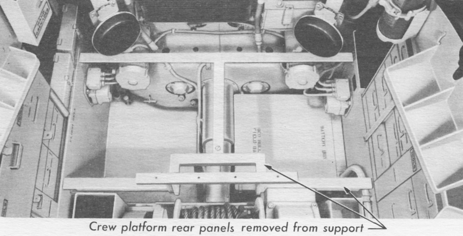
With the crew platform rear panels removed, the relocation of the battery box to the left rear corner of the crew compartment can be seen. The recovery vehicle lacked the auxiliary generator engine that was installed in medium tanks, and the fixed fire extinguisher cylinders, visible in the upper right corner, were relocated to the area formerly occupied by the auxiliary generator. The folding rear crew seats are also demonstrated in this picture. (Picture from TM 9-738 Tank Recovery Vehicles M32, M32B1, M32B2, M32B3, and M32B4.)
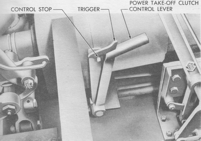
The power take-off clutch control lever was moved to the forward position to engage the power take-off clutch, and to the rear to disengage the clutch. If engagement of the power take-off clutch was difficult, the vehicle clutch could be gently slipped to aid its engagement. (Picture from TM 9-738 Tank Recovery Vehicles M32, M32B1, M32B2, M32B3, and M32B4.)
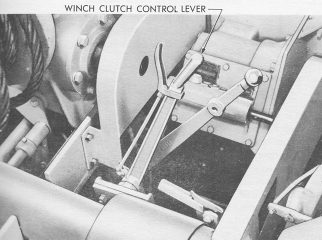
The front of the vehicle is to the right of this image. The winch clutch control lever was moved forward to engage the winch clutch, the winch clutch was disengaged by moving the lever back, and the drag brake was applied by moving the lever farther to the rear. Positioned in the picture, the lever would be applying the drag brake. The drag brake applied slight resistance with the lever in neutral, and its force increase with the rearward movement of the lever. The lever behind the winch clutch control lever is the winch gearshift lever. From front to rear, its positions were for low, neutral, reverse, neutral, and high. In the image, it is positioned in neutral between reverse and low. (Picture from TM 9-738 Tank Recovery Vehicles M32, M32B1, M32B2, M32B3, and M32B4.)
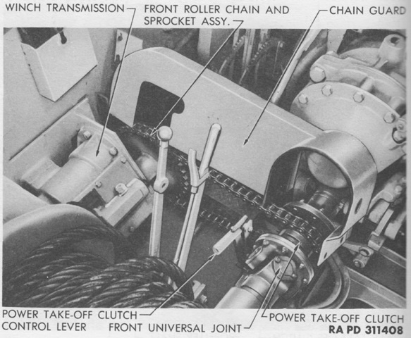
The front chain guard is in the process of being removed in this picture, revealing the roller chain engaged by the power take-off clutch that provided power from the vehicle's propeller shaft to the winch. (Picture from TM 9-738 Tank Recovery Vehicles M32, M32B1, M32B2, M32B3, and M32B4.)
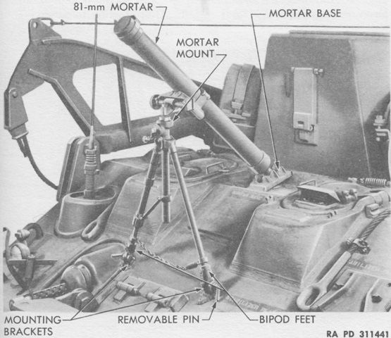
The 81mm mortar M1's bipod feet were secured to the hull by removable pins, allowing the ordnance to be removed when necessary and emplaced on the baseplate carried in the vehicle. The mortar weighed 44.5lb (20.2kg), the bipod was 46.5lb (21.1kg), and the portable baseplate for ground use weighed 45.0lb (20.4kg). The mortar was 49.5" (126cm) long overall. (Picture from TM 9-738 Tank Recovery Vehicles M32, M32B1, M32B2, M32B3, and M32B4.)
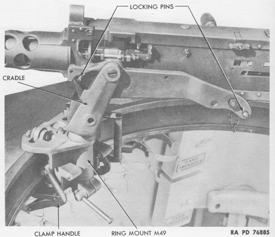
Details of the machine gun skate and cradle on the ring mount M49 can be seen here. (Picture from TM 9-738 Tank Recovery Vehicles M32, M32B1, M32B2, M32B3, and M32B4.)
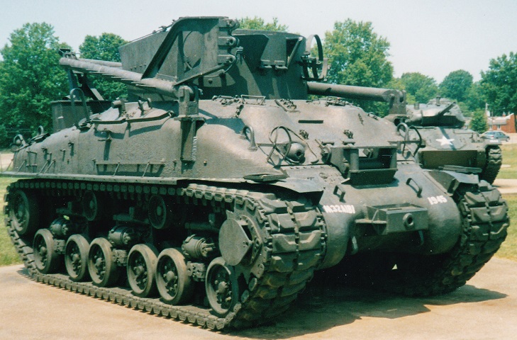
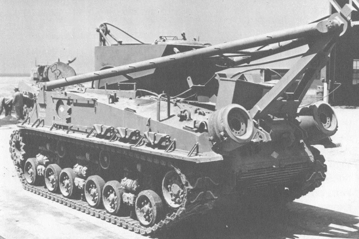
The rounded hull on this vehicle indicates it's an M32B1. The crane boom is stowed, and stowage boxes and spare road wheels are present on the rear deck, while drive sprocket rings are present on the turret sides. A towing bar can be seen under the crane boom on the hull side, and spare track shoes are stowed on the hull rear. (Picture from ORD 8-9 SNL G-185 List of All Service Parts for Vehicle, Tank Recovery, M32, M32A1, M32A1B1, and M32B1 (SNL G-185) Vehicle, Tank Recovery, M32B3 and M32A1B3 (SNL G-187).)
The front of the same vehicle is seen. (Picture from ORD 8-9 SNL G-185 List of All Service Parts for Vehicle, Tank Recovery, M32, M32A1, M32A1B1, and M32B1 (SNL G-185) Vehicle, Tank Recovery, M32B3 and M32A1B3 (SNL G-187).)
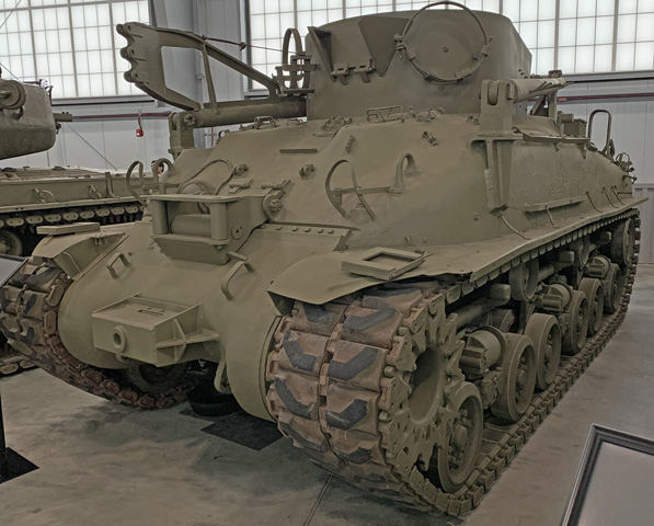
This M32A1B1 lacks the 81mm mortar, and its A-frame boom still uses the lifting arm on the right strut. This vehicle's lifting arm has three connections, rather than the two of earlier production models. The top and bottom connections were for upward and downward slopes, respectively, while the center was for raising the boom on level ground. A lifting drum is attached to the right drive sprocket, the bow machine gun is retained, and leads for the winch are visible on the hull front. The nonrotating turret includes curved plates, which is indicative of a later production vehicle. The tracks on this TRV are the rubber block T84.
The vehicle is seen from the opposite side. Straps for securing spare wheels are on each side of the turret front, while a tow bar would be stowed on the final drive and differential cover and sprocket rings would be placed in the racks along the hull sides. Another tow bar could be stowed in the tall strap on the rear upper hull side. Note that the cable door on the turret front has been enlarged from the design of the vehicle featured in the technical manual images.
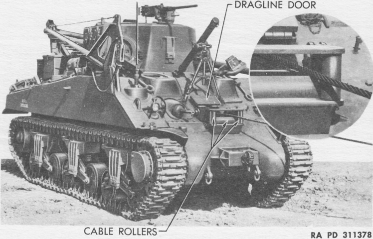
The bow machine gun was retained, but would possess a reduced cone of fire due to the winch cable rollers on the hull front. The sockets for the mortar legs are visible on each side above the dragline door.
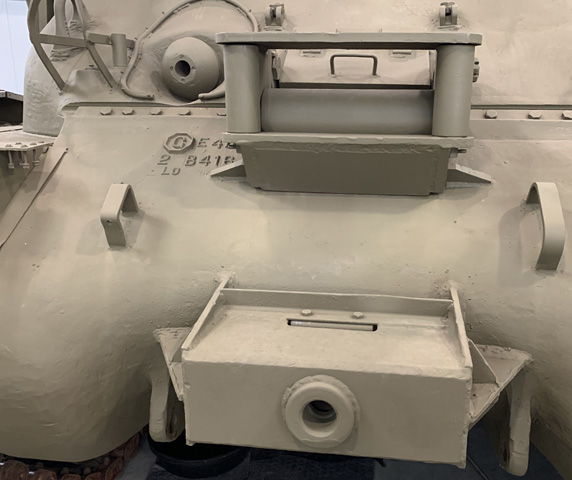
The dragline door and cable roller assembly is highlighted in this image. The mortar leg sockets are better seen as well.
The dragline door, cable rollers, and front towing pintle are shown from ahead. A towing bar was stowed under the straps welded to the final drive and differential cover.
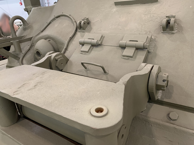
The plate welded to the left front fender for attaching implements such as a vise is detailed in this image. A similar plate was attached to the right fender.
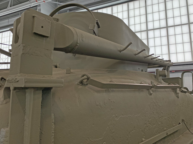
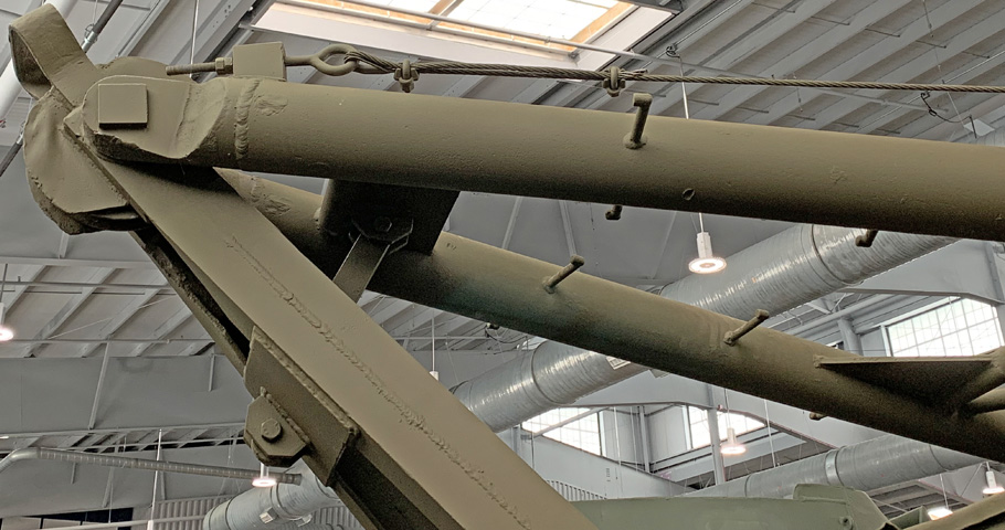
The left hinge for the boom assembly and its attachment to the hull are shown here; the steps on the boom seem to present a perilous voyage. Stowage for spare sprocket rings is on the hull side, and a towing bar would be secured under the tall loop on top of the rear hull side.
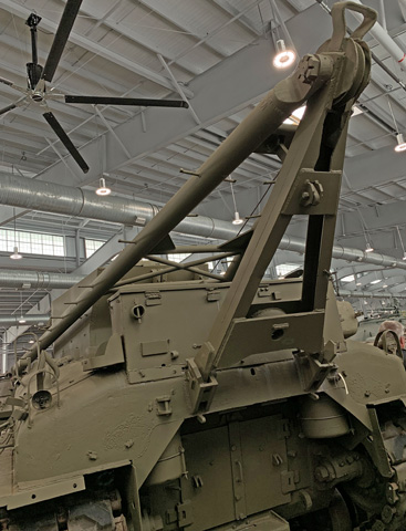
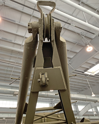
The right side boom hinge and support are seen as well as the boom's lifting arm with its three attachments.

The lifting arm is shown from the opposite site, with the boom support cable secured to the top of the lifting arm.
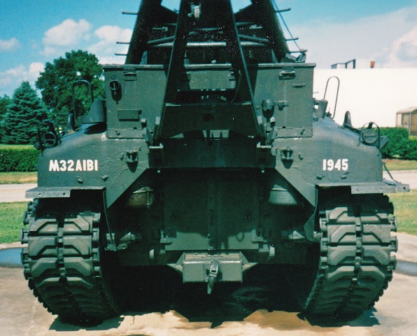
The engine access doors can be seen on the lower hull, and the engine air cleaners are outboard of these doors, protected by additions to the hull rear armor. A towing pintle is mounted below the engine doors, and a stowage box is on the rear deck. The A-frame that locks the crane boom in the stowed position is attached to the upper hull rear plate.
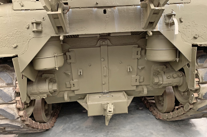
A closer look at the engine doors shows where the additional armor for the air cleaners was added to the hull rear. The rectangular engine exhaust pipes can just be seen peeking out from under the hull rear armor between the air cleaners, and the stout supports for the A-frame are obvious. The hole in the center of the upper rear hull plate was for the radial engine's hand crank, and fittings for an exhaust deflector have been welded to the engine access doors and just inboard of the air cleaners on the underside of the hull upper rear plate, although the deflector is not mounted. The eccentric idler wheel adjustment mechanisms are also better seen.
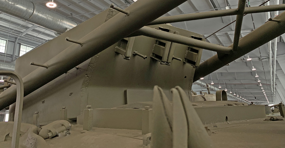
A wider view of the A-frame attaching to the stowed boom is provided here. Steps were also welded to the inside of the boom arms along their upper portions, when clearance was obtained from the turret sides when stowed. Fittings for securing large tools are visible on the exterior of the rear stowage box.
The boom sheave and A-frame attachment are seen from below.
More details of the A-frame and boom securing attachments are provided in this image, along with the other end of the boom support cable.
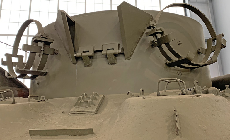
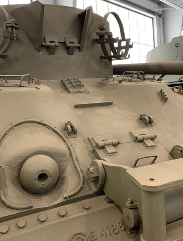
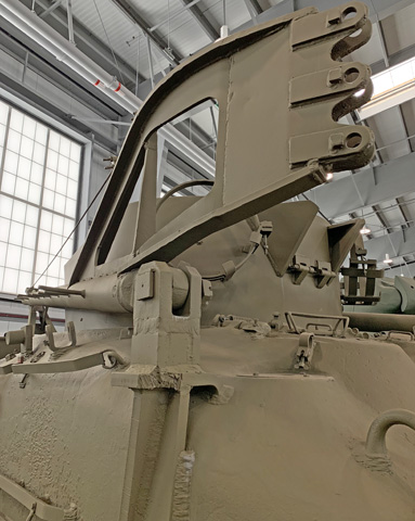
The straps for securing spare road wheels to the turret front can be seen here, as well as the door in the turret front for the boom cable. The guards on each side of the door appear to prevent it from opening all the way down, which would presumably be unnecessary since the cable would be exiting the turret at an upward angle. Sockets for the mortar tube ball are welded to the hull between the drivers' positions.
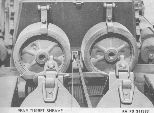
Spare tracks were stowed on the upper portion of the turret rear, and the rear turret sheave was below.
With spare road wheel stowage no longer crowding the sides of the turret rear door, a wider design could be implemented.
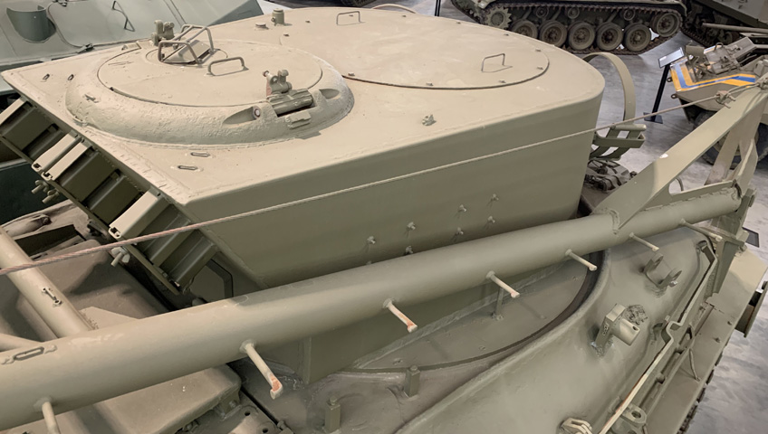
The machine gun mounting ring has been removed and plated over, but the locations of it and the turret escape hatch to the rear are seen.
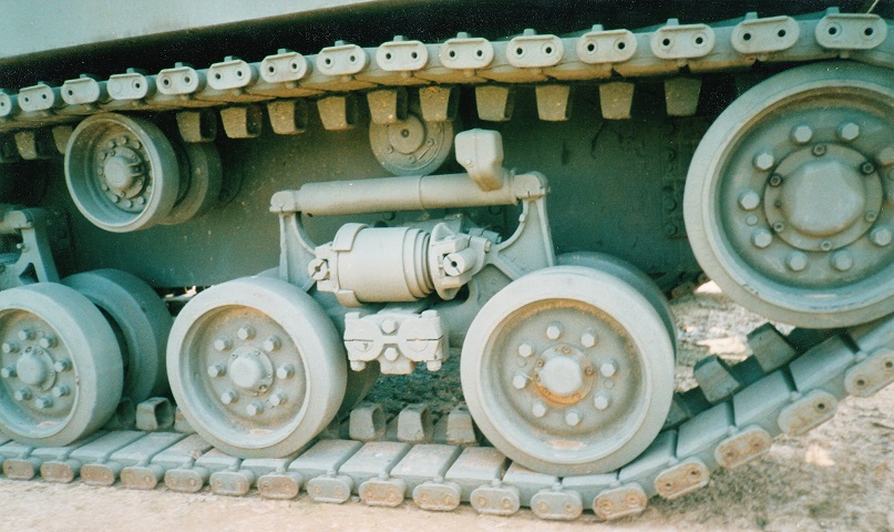
A horizontal volute spring suspension bogie is highlighted here. The spring is centrally mounted below the shock absorber. The single and dual track return rollers are visible, and the change to dual road wheels is obvious. HVSS allowed the use of wider track and improved the performance compared to the earlier vertical volute spring suspension, and it was authorized for production on all models of the Sherman tank in March 1944.
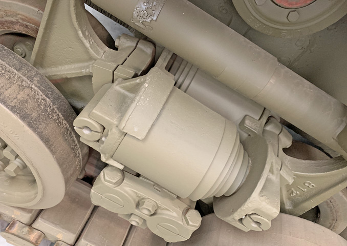
The inner volute spring is more visible from this angle.
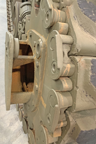
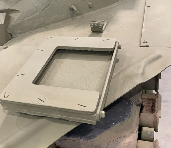
With the switch to HVSS and its new hollow drive sprocket hub, the design of the lifting drum was modified as well.
The boom is stowed on this vehicle, attached to the rear A-frame. Stowage boxes are placed around the rear deck, and the loop on the left rear upper hull was a catch for stowing a towing bar. Road wheels are kept on the rear hull, and sprocket rings are now placed on the fenders. Just visible in front of the turret is the top of the late-production hull-mounted boom raising sheave that replaced the lifting arm formerly found on the right strut of the boom. (Picture from Tank Data, vol. 2.)
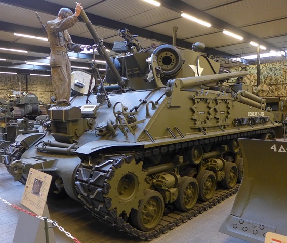
The mannequin on this vehicle is shown loading the 81mm mortar on the front hull plate. The mortar could be traversed 300 mils to the right or left, and could also be dismounted for use with a ground base plate. (Picture courtesy Dackelone.)
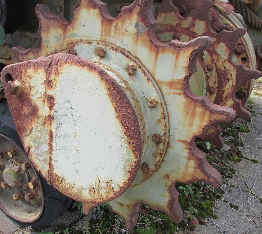
Details of the lifting drum on this rusty drive sprocket can be seen in this image.
